Electrical Engineering Principle CHAPTER V AC AND DC


 induced e. m. f. •")


 Flux distribution in air gap due to field current only (b) flux distribution")


 Method of Neutralizing Effect of armature Reaction for")
 Shifting of brushes • By the shifting the brushes to the new MNA,")
 Use of commutating poles")
 Use of compensating winding")


 Series Generator. Arma_ ture N")
 Shunt Generator Arma-ture N S (a) + - (b)")
 Compound generator. Shunt field Series field Armature S Shunt field Arma")


 Hysteresis")


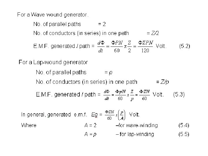
 With the armature lap connected, number of parallel paths in the armature")
 With the armature wave connected, No. of parallel paths = 2 No. of")


- Slides: 47
Electrical Engineering Principle CHAPTER V AC AND DC MACHINE FUNDAMENTALS
5. 1. DC GENERATOR. The knowledge that students can obtain from this chapter are: 1. The principle of a basic DC generator with construction, related equations and type of windings. 2. Explanation on armature reaction, commutation and type of DC generators. 3. Understanding of losses occurs in DC generators.
5. 1. 1 Principle. • An electrical generator is a machine which converts mechanical energy into electrical energy. • The energy conversion is based on the principle of the production of dynamically (or motionally) induced e. m. f.
The principle of the production of dynamically (or motionally) induced e. m. f. • • The basic essential parts of an electrical generator are (i) a magnetic field and (ii) a conductor or conductors which can so move as to cut the flux. For making the flow of current unidirectional in the external circuit by split ring. The split rings are made out of a conducting cylinder which is cut into two halves or segments insulated from each other by a thin sheet of mica or some other insulating material. As before, the coil ends are joined to these segments on which rest the carbon or copper brushes
The wave form of the current through the external circuit q The first position shows that the conductor with vertical position does not cut magnetic flux, so there is no current flowing in the conductor and the induced emf curve shows zero. q In the second position the conductor moves and turns right and cuts the magnetic flux with the horizontal position. Here the emf induced is maximum as shown at the induced emf curve. q Then the third position conductor moves again and is placed like the first position and there is no current flowing in the circuit. q The fourth position like the second position is maximum induced emf. q Next, the conductor comes back to the first position. q So this condition is called 1 revolution.
5. 1. 2 E. M. F. Equation of a Generator • Wave form of e. m. f
• Hence, according to Faraday’s laws of Electromagnetic Induction,
5. 1. 3 DC General Construction
5. 1. 4 Armature Winding • Simplex Lap-Winding Lap Winding connected to commutator bars
• Simplex Lap Winding, Development Form
Single turn coil in lap winding • • • The back and front pitches are odd and of opposite sign. But they cannot be equal. They differ by 2 or some multiple thereof. Both YB and YF should be nearly equal to a pole pitch. The average pitch YC = Commutator pitch YC = ± 1 Resultant pitch YR is even , being the arithmetical difference of two odd numbers. The number of slots for a 2 layer winding is equal to the number of coils ( i. e. , half the number of coil sides). The number of commutator segments is also the same.
Simplex Wave Winding • Simplex Wave Winding, Development Form
Single turn coil in wave winding • • • The number of coils i. e. NC can be found from relation NC = Both pitches YB and YF are odd and of the same sign Back and front pitches are nearly equal to the pole pitch and may be equal or differ by 2, in which case, they are respectively one more or one less then the average pitch. Resultant pitch YR = YF + YB. Commutator pitch YC = YA (in lap winding, YC = ± 1). YC = • The average pitch which must be an even integer is given by • YA =
5. 1. 5 Armature Reaction and Commutation • When a dc generator is loaded, the armature mmf flux reacts with the field flux and thereby distorts the distribution flux in the air gap. The magnetic neutral axis shifts from the geometrical neutral axis, i. e. from the inter-polar region. This adversely affects the reversal of current in a conductor passing under the brush.
5. 1 Armature Reaction • Flux distributions in the air gap due to the field excitation only
(a) Flux distribution in air gap due to field current only (b) flux distribution due to armature current only (c) Flux distribution due to the combined effect of field current and armature current.
Brush axis shifted to new magnetic neutral axis created due to armature reaction
5. 1. 5. 2 Commutation • The process by which current in a coil is reversed during the period in which it passed under the brushes is called commutation. The period during which a coil undergoing commutation remains short circuited is known as the commutation period. The commutation period is shown by the period which is taken for coil AA’ to change it is position
Period of commutation i. e. the time taken by the armature coil AA’ to pass under the brushes while rotating
5. 1. 5. 3 • (i) Method of Neutralizing Effect of armature Reaction for Better Commutation. Use of high brush contact resistance.
(ii) Shifting of brushes • By the shifting the brushes to the new MNA, sparkles commutation can be achieved. This has been explained earlier. The brushes are to be shifted by a certain angle in the forward direction (in the direction of rotation), in generator. The disadvantage with this method is that the angle of shift will depend upon the load on the machine and therefore is practically difficult to arrange.
(iii) Use of commutating poles
(iv) Use of compensating winding
5. 1. 6 Operation dc generator. • Separately excited generator. • Self Excited Generator. – Series Generator. – Shunt Generator. – Compound generator.
5. 1. 6 Operation dc generator • 5. 1. 6. 1 Separately excited generator. Ia If Armature Armatur e N S Vf Field + LOAD N DC Supply - Rf Ea Ra Vt L o a d RL
5. 1. 6. 2 Self Excited Generator. • a) Series Generator. Arma_ ture N S (a) - + (b)
• b) Shunt Generator Arma-ture N S (a) + - (b)
• c) Compound generator. Shunt field Series field Armature S Shunt field Arma ture (b) (a) - + Series field
5. 1. 7 The basic analysis of DC generator • Separately excited generator. Ia If Ea = V + Ia. Ra Vf Rf Ea, Ra V If =
Series generator. Rs Ia Fig. 5. 27 Is Ea, Ra V RL Ea = V + Ia. Ra + Is. Rs Ia = Is Ea = V + Ia(Ra+Rs)
Shunt Generator If IL Ia Rf Ea, Ra Fig. 5. 28 V RL Ea = V + Ia. Ra V=IL. RL Ia = If + IL If =
Long Compound. If Rs IL Fig. 5. 29 Ia Rf Ea, Ra V RL Ea = V + Ia. (Ra + Rs) Ia = If + I L V = If. Rf = I L. RL
Short Compound Rs If Is Fig. 5. 30 Ia Rf Ea, Ra V RL Ea = V + Ia. Ra + Is Rs Ia = If + Is If. Rf = V + Is. Rs
5. 1. 8 Iron Loss in the Armature Core • ( i. ) Hysteresis loss ( Wh) • (ii) Eddy Current Loss. (We)
According to Steinmetz formula; Joule/second or watt Where ; density is 1. 5 f = PN/120 = frequency of magnetic reversal P = No. of pole N = the armature speed in r. p. m. Bmax = maximum value of flux density [normal flux Wb/m 2] Vc = volume of core in m 3 K = Steinmetz hysteresis coefficient [ for good dynamo sheet steel = 502 J/m 3, silicon steel = 191 J/m 3]
The expression for eddy current loss can be represented as watt Where ; Bmax= maximum flux density f. = frequency of magnetic reversal t = thickness of each lamination Vc = volume of armature core.
5. 1. 9 Total Loss in a DC Generator Copper losses Total Losses Iron Losses Mechanical Losses Armature Cu Loss Shunt Cu Loss Series Cu Loss Hysteresis Eddy Current Friction Windage
POWER STAGES. A Mech. Power input = output of driving engine B Iron and friction losses Elect. Power developed in Cu armature Losses = E. Ia watts C Elect. Power output = V. I watts
Testing and efficiency
Example 5. 1. 1 An eight pole armature is wound with 480 conductors. The magnetic flux and the speed are such that the average e. m. f. generated in each conductors is 2. 2 V, and each conductor is capable of carrying a full load current on full load and the total power generated on full load when the armature is (a) lap connected; (b) wave connected
Solution (a) With the armature lap connected, number of parallel paths in the armature winding = number of pole = 8. No. of conductor per path = Terminal voltage on no load = e. m. f. per conductor x number of conductors per path which is 2. 2 x 60 = 132 V Output current I full load is Full load current per conductor x no. of parallel paths = 100 x 8 = 800 A Total power generated on full load is Output current x generated e. m. f. = 800 x 132 = 105. 6 k. W
(b) With the armature wave connected, No. of parallel paths = 2 No. of conductor per path = Terminal voltage on no load = e. m. f. per conductor x number of conductors per path which is 2. 2 x 240 = 528 V Output current I full load is Full load current per conductor x no. of parallel paths = 100 x 2 = 200 A Total power generated on full load is Output current x generated e. m. f. = 200 x 528 = 105. 6 k. W
Example 5. 1. 2 A four pole wave connected armature has 51 slots with 12 conductors per slot and is driven at 900 r/min. If the useful flux per pole is 25 m. Wb, calculate the value of the generated e. m. f.
Solution Total number of conductors = Z = 51 x 12 = 612 ; A = 2 ; P = 4; N = 900 r/min ; Ф = 0. 025 Wb. The value of the generated e. m. f is E= V
Example 5. 1. 3 A shunt generator delivers 450 A at 230 V and the resistances of the shunt field and armature are 50 Ω and 0. 03 Ω respectively. Calculate the generated e. m. f. explain what happen if the value of shunt field resistance increase?
Example 5. 1. 3 A shunt generator delivers 195 A at a terminal p. d. of 250 V. The armature resistance and shunt field resistance are 0. 02 Ω and 50 Ω respectively. The iron and friction losses equal 950 W. Find (a) e. m. f. generated; (b) Cu losses ; (c) Output the prime mover and (d) Commercial, mechanical and electrical efficiencies.