Cryomodule options for the ERL of the LHe


- Slides: 24

Cryomodule options for the ERL of the LHe. C, FCC_eh (and Perle) Sebastien Bousson & Gilles Olivier LHe. C/FCCeh and Perle Workshop, Orsay, 27 th-29 th June 2018

Cryomodules The main functions of a cryomodule • Give the cryogenic environment for the cold mass, i. e. the cavity and/or magnet (only cavity in the ERL case): perform the cryofluids distribution • Helium (LHe) and/or Nitrogen (LN) • Handle the liquid and vapor phase of the cryofluids Ø Cavity operating temperature: 4 K (atm. Pressure) or 2 K (~30 mbar) Ø Thermal shield could be actively cooled by cold He gaz or LN Ø Power coupler might required an active cooling • Vacuum • Perform thermal insulation against all heat transfer from room temperature to the cold mass: • limit losses by conduction, convection or radiation • Supporting and positioning of the components: • Structural support for the cold mass • Precise alignment of the cavities with respect to the beam axis and keep the alignment over thermal cycles • Provide magnetic shielding to the cavities S. Bousson, LHe. C/FCCeh and Perle Workshop, Orsay, 27 -29 June 2018 -2 -

Cryomodules in LHe. C CDR: • Number of cryomodules: 2 x 60 • Number of cavities per cryomodule: 8 (with Q 0 2. 5 1010) • Number of refrigerators: 8 (one per 250 m of linac) • Operating temperature: 2 K • Total cryogenic power @ 4. 5 K: 80 k. W (no uncertainties factors taken) (largely dominated by dynamic load) S. Bousson, LHe. C/FCCeh and Perle Workshop, Orsay, 27 -29 June 2018 -3 -

Cryomodule requirements for ERLs Several cryomodule requirements could be listed for ERLs, and some of them are very challenging. They are of two types: 1. The classical challenges imposed by SRF: • Limit as much as possible heat transfer • Take into account all mechanical constraints • Design allowing an easy assembly procedure • … and as usual, optimize for cost ! 2. The additional constraints coming from the cavities operated in the ERL mode and CW/high current operation mode: • High CW cryo loads • Low level of vibration, and damping of them • Excellent magnetic shielding (high Qo) • Accurate cavity alignment S. Bousson, LHe. C/FCCeh and Perle Workshop, Orsay, 27 -29 June 2018 -4 -

The classical challenges in designing SRF cryomodules

Generic constraints for cryomodule design 1. Limit as much as possible heat transfer • Cold mass (spoke cavities) needs to operate at 2 K. And 1 W dissipated @ 2 K costs ~700 W of electrical power to maintain @ 2 K ! -> optimization of running cost for the accelerator • The 3 heat transfer mechanisms: • Use of material exhibiting poor thermal conductivity • Use small sections for the interface rods • Use thermal intercepts • Operate in vacuum ! • Use thermal shields at intermediate temperature • Use low emissivity materials • Use multi-layer insulation S. Bousson, LHe. C/FCCeh and Perle Workshop, Orsay, 27 -29 June 2018 -6 -

Generic constraints for cryomodule design 2. Mechanical constraints • Isolation vacuum: The cryomodule external vessel has to sustain external pressure • Thermal gradients: Thermal contractions induces mechanical constraints • Gravity: component mass A fully equipped cavity can weight > 250 Kgs They all have an impact on the alignment and component stability Temperature map in the ESS spoke cryomodule (P. Duchesne, IPNO) • Use material with low thermal contraction coefficient (ex: Ti. A 6 V, composite materials) • Use geometrical “tricks” to add flexibility (bellows, bended tubes, …) • Use of materials with high elastic limit to sustain the forces S. Bousson, LHe. C/FCCeh and Perle Workshop, Orsay, 27 -29 June 2018 -7 -

Generic constraints for cryomodule design 3. Assembly and maintenance constraints • The cavity string is prepared and sealed in a clean room ØReduce as much as possible the amount of material inside clean room for improved contamination control Ø Optimize the number of assembly operations inside the clean room • Design a cryomodule which can be “easily” assembled and maintained Ø Optimize parts and components access Ø During all assembly steps, maintain or control/monitor alignment 4. Cost constraint ! Ø Obvious: optimize the cryomodule component cost but also the required amount of manpower to assemble Ø Also think about the cost of assembly tooling S. Bousson, LHe. C/FCCeh and Perle Workshop, Orsay, 27 -29 June 2018 -8 -

Keeping cavity perfs: XFEL Experience Comparison between XFEL cavity performances achieved in VT vs CM Accelerating gradient -> degraded by 3% in average (modulated by administrative limit at 31 MV/m Quality factor -> no clear trend (but difficult to measure on cryomodule) S. Bousson, LHe. C/FCCeh and Perle Workshop, Orsay, 27 -29 June 2018 -9 -

Specific challenges of ERLs cryomodules

Specific constraints in ERLs cryomodules High cryo loads generated by the CW and high current operation mode • A large number of significant dynamic heat loads in an operation mode where dynamic loads are >> static loads • Cavity • High order Mode (HOM) couplers • CW input couplers • Design question/optimization points to find for cryostat/cryoplant: cryo load • Thermal shield temperature optimum • How to efficiently extract HOM power, at what T° • Cryo load varies a lot between RF on/off : cryoplant (and cryogenic distribution) flexibility is required • Cavity optimum operating temperature: cost vs cavity performances vs helium bath stability • Keeping the cavity high Qo -> cryostat design optimized for magnetic shielding • How to cool the cavities (series/parralel) in order to insure “magnetic hygiene” (is this really an issue for high Qo @ 802 MHz ? ) S. Bousson, LHe. C/FCCeh and Perle Workshop, Orsay, 27 -29 June 2018 - 11 -

Specific constraints in ERLs cryomodules • Design question/optimization points to find for cryostat: vibrations management • How to insure low mechanical vibrations levels – what is the source ? • How to damp vibrations to ease cavity control • Design question/optimization points to find for cryostat: magnetic shielding (required for high Qo, required cavities submitted to les than a few m. G) • What magnetic material, at what temperature ? -> data available now • How many layers of magnetic shield ? • Active shielding could help ? • Very few worldwide experience of magnetic shielding requirements for high Qo at frequencies in the 500 – 800 MHz range S. Bousson, LHe. C/FCCeh and Perle Workshop, Orsay, 27 -29 June 2018 - 12 -

Design options for ERL cryomodules

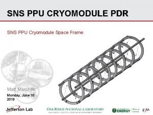
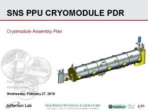
Cryomodule type #1: SNS or ESS like • Developed first by SNS and then adapted and improved for ESS • Specific characteristics: • Cold mass supported by the “spaceframe” : an assembly tooling remaining in the cryostat • Side loading ESS S. Bousson, LHe. C/FCCeh and Perle Workshop, Orsay, 27 -29 June 2018 - 14 -

Cryomodule type #2: ILC or XFEL-like • Developed for Flash, XFEL (and LCLS-II) and ILC • Specific characteristics: • Long cryostat (8 cavities) • Continuous cryogenic line (reduced number of cold/warm transition • Gaz return pipe as the mechanical supporting system for the cavity string S. Bousson, LHe. C/FCCeh and Perle Workshop, Orsay, 27 -29 June 2018 - 15 -

Cryomodule type #3: SPL-like • Developed within the SPL project framework by IPNO and CERN • Specific characteristics: • Full length top-lid closure • Cold mass supported by power coupler S. Bousson, LHe. C/FCCeh and Perle Workshop, Orsay, 27 -29 June 2018 - 16 -

SPL prototype short cryomodule to be use as the prototype PERLE cryomodule ?

POTENTIAL REUSE OF THE SPL/HG CRYOMODULE DESIGN AND COMPONENTS For more details about SPL (HG) cryomodule: presentation of Luca DASSA. PERLE workshop, Daresbury on January 15 th , 2018. Design of the cryomodule performed by IPNO and updated by CERN. Vacuum vessel and most of cryogenic lines delivered. CAN THIS DESIGN AND THESE COMPONENTS BE REUSED FOR PERLE @ ORSAY ? 18

MAIN DIMENSIONAL CHARACTERISTICS OF THE CAVITIES CHARACTERISTICS SPL (704 MHz) PERLE / JLAB (802 MHz) Coupler to coupler length (mm) 1490, 5 - Length flange to flange (mm) 1397, 3 1292, 5 Coupler to flange dimension (mm) 116, 4 96, 7 Cells external diameter (mm) 386, 5 335 Beam port internal diameter (mm) 129, 8 / 139, 8 (coupler side) 130 Flanges internal diameter (mm) 79, 7 (CF 100) 130 (CF 160) Vacuum valve diameter CF 63 tbd Coupler internal diameter (mm) 100 Coupler flange CF 100 Beam axis to ext. coupler flange 403 tbd SIMILAR FEATURES 19

SPL CAVITY STRING POSITIONING & CRYOSTATING PROCEDURES The cavities are supported and positioned directly by their coupler flange. The opposite side (with respect to the coupler) of each cavity is supported and positioned by means of a spherical joint fixed on the next cavity. Max: 0. 12 mm Déformée du train Displacement of thede cavités (poids propre seul) cavity string alone (weight only) Courtesy of P DUTHIL / S ROUSSELOT (IPNO) Cavity string equipped with magnetic shield, CTS, cryogenic lines and thermal shield Insertion of the complete assembly inside the vacuum vessel Closing of the top lid and of the beam ports 20

BEAM VACUUM VALVES NEED OF A "TWO STAGES" SOLUTION TO USE AN ALL METAL GATE VALVE CF 63 "Vatterfly" valve with manual Maximum valve height: 180 mm (from beam axis) actuator VAT Ref. 20336 -CE 14 All metal gate valves (commonly used) < 1. 10 -10 mbar. l/s < 1. 10 -10 mbar Height of all metal gate valves (VAT series 48)with pneumatic actuator: CF 40: 312 mm CF 63: 527 mm All metal 21

HOM EXTRACTION - How many extraction ports (interferences with CTS)? Which power (W, tens of W, more)? What kind of damper (waveguide, loop coupling)? Active helium cooling or thermalization by copper braids What kind of RF line to the external load (cable sufficient, which kind of connector)? Intermediate thermalization of the cables External cooled RF loads POTENTIALLY THE MAIN ISSUE DUE TO THE LACK OF SPACE Loop coupling with active cooling. Courtesy of CERN Waveguide HOM coupler. Courtesy of Brookhaven NL 22

POTENTIAL REUSE OF THE SPL/HG CRYOMODULE DESIGN AND COMPONENTS - Vacuum vessel could be reused without refurbishing Cryogenic lines to be adapted? Thermal and magnetic shields designed but not yet purchased. They can be modified. - The internal space is almost full Risk of interference between CTS and HOM dampers The reuse of the cryomodule will depend on the number and the type of the HOM dampers 23

Any question ?
 Ge erl
 Logistics
 Erl tesla 4000
 Erlphase tesla 4000
 Erl diagram
 Erlphase power technologies ltd.
 Deus chama abraão e lhe faz promessas
 Analise do poema perdigão perdeu a pena slideshare
 Só sei que maria de nazaré resolveu se casar com josé
 Este classe e subclasse
 Teckenspråk minoritetsspråk argument
 Etik och ledarskap etisk kod för chefer
 Offentlig förvaltning
 Humanitr
 Datorkunskap för nybörjare
 Antika plagg
 Rita perspektiv
 Ministerstyre för och nackdelar
 Gumman cirkel
 Tack för att ni lyssnade bild
 Claes martinsson
 Sju principer för tillitsbaserad styrning
 Nyckelkompetenser för livslångt lärande
 Vad är prosa
 Personlig tidbok för yrkesförare
