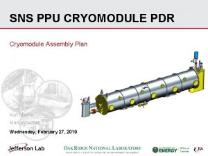
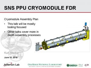
Status of Compact ERL c ERL cryomodule with


![Courtesy of F. Qiu. T. Miura Field-detuning Map (ML 1, ML 2) Vc[MV]=1. 038[m] Courtesy of F. Qiu. T. Miura Field-detuning Map (ML 1, ML 2) Vc[MV]=1. 038[m]](https://slidetodoc.com/presentation_image_h/35352386e1095f369fa4cfff70449461/image-19.jpg)


- Slides: 32

Status of Compact ERL (c. ERL) cryomodule with beam Compact ERL (c. ERL) Hiroshi Sakai (KEK) (On behalf of c. ERL development team) Compact ERL (c. ERL) has been constructed in 2013 at KEK to demonstrate energy recovery with low-emittance, high-current CW beams of more than 10 m. A for future multi-Ge. V ERL & CW-FEL. 2019: c. ERL was re-organized under the (CASA) in KEK to promote the industrial application by using c. ERL. 20 Me. V Circumference ~ 90 m Beam Dump 20 Me. V Main LINAC 9 -cell SC cavity x 2 Marger Injector LINAC 3 -5 Me. V ©Rey. Hori/KEK 2 -cell SC cavity x 3 Photocathode DC gun (Not SRF gun) 26 pages 8 th Buncher RF frequency= 1. 3 GHz • (Introduction) • (A) The latest c. ERL beam operation and Application by using c. ERL beam • (B) SRF cryomodule performance and SRF activity of c. ERL KEK-IHEP SCRF Collaboration meeting @ (2 nd. -3 rd Dec. 2019)

(Introduction) c. ERL beam operation for Applications • Super conducting accelerator with ERL scheme gives us high current linacbased electron beam (~10 m. A) with high quality of the electron beam such as small emittance, Short pulses. • The unique performance gives us several important industrial applications as follows. Already achieved these application by – High resolution X-ray imaging device for medical use using Laser Compton – Nuclear security system (gamma-ray by LCS) Scattering (LCS) Exp. – (1) RI manufacturing facility for nuclear medical examination – (2) EUV-FEL for Future Lithography for industrial application Next targets in a few year – (3) Intense THz light generation Plan of c. ERL beam operation (2018~2020) • New beam line for 99 Mo RI production & material irradiation in c. ERL. (from 2019) • We will produce FEL with this high current beam in the IR-FEL regime. (POC of EUV-FEL plan) Including high charge beam operation (~60 p. C). • < 200 fs bunch operation with THz generation (RCDR experiment) c. ERL beam line New beam line for 99 Mo & material irradiation New THz beam line IR-FEL undulator

Construction and Commissioning of c. ERL Laser Compton scattering experiment in ERL T. Akagi, et. , al. “Narrow-band photon beam via laser Compton scattering in an energy recovery linac” Phys. Rev. Accel. Beams 19, 114701 (2016) 2008 2009 2010 2011 2012 (Published) M. Akemoto et al. , “Construction and commissioning of the compact energy-recovery linac at KEK” Nucl. Instrum. Method A 877 p. 197 -219 (2018). Commissioning started 2013 2014 2015 R&D for Industrial application 2016 2017 2018 2019 Beam operation RI beam test & production High bunch charge & THz study Construction Increasing the beam current Commissioning/Operation Construction of RI beamline 1 m. A again Commissioning of LCS system Construction of LCS system Commissioning of c. ERL (with loop) Construction of recirculation loop Commissioning of injector Construction of injector Refurbishment of building Clearing radioactive materials Construction of radiation shielding Construction of IR-FEL Today’s presentation c. ERL beam operation from 2018 to Oct. 2019 Period Energy Current (operation [Me. V] [m. A] time) Comment) 2018. Mar. 17. 5 60 p. C/ (2 weeks) bunch 2018. Jun. 17. 5 60 p. C/ (4 weeks) bunch & 1 m. A (CW) 2019. Apr. 17. 5 60 p. C/ (4 weeks) bunch 2019. Jun. (4 weeks) 2019. Oct. (4 weeks) 17. 5 19. 5 (3. 5 k. Pa operation) Construction started in 2009 and commissioning start in 2013. Now we continue beam operation in 2019 2020 1 m. A ERL achieved 60 p. C/ bunch & CW beam (<10μA) 3

(A) The latest c. ERL beam operation and Application by using c. ERL beam (2018 – 2019. Jun) (1) RI manufacturing facility for nuclear medical examination (2) EUV-FEL for Future Lithography for industrial application (3) Intense THz light generation The presentation of this part (A) is same as my presentation of “Industrial application of c. ERL” of LCWS 2019 workshop held on Sendai/Japan

(1) RI manufacturing facility for nuclear medical examination (99 Mo/99 m. Tc) Concern about the stable supply of 99 Mo / 99 m. Tc is almost 100% imported, even though the largest number of applications in nuclear medicine diagnosis • Problem of the stable air transportation (Problem caused by volcanic eruption in the past) • Most 99 Mo is manufactured in nuclear reactor • Due to the aging of nuclear reactors, stable supply in the future is a big issue • 99 Mo Development of RI manufacturing (99 Mo / 99 m. Tc) by using accelerator for stable supply 99 Mo A few 10 Me. V Electron Beam Bremsstrahlung (g, n) reaction A state of brain blood flow revealed by nuclear medicine diagnosis by 99 m. Tc Required Specification for accelerator (final) • 20 ~ 50 Me. V electron beam • Several m. A to 10 m. A 5

Test Experiment to produce 99 Mo in c. ERL is preparing • The test irradiation of electron beams to a multiple molybdenum target will be done at this fiscal year to produce 99 Mo and check the yield of the production in order to realize a real machine with large electron beam power. start 10 u. A with 20 Me. V (max) electron CW beam • It is necessary to get several knowledge to design a target system for large irradiation power such as a practical technique for 99 Mo production, target thermal design, shielding radiation design and legal procedures, etc. It is the final objective of this project. Target Be window Beam line was constructed in Mar. 2019. And beam test started in Apr. 2019. Mo 20 Me. V 10 m. A(maximum) We are engaged in R & D on utilization of accelerator beams for radioisotope generation and reforming of organic matter under research contract with “Accelerator Inc. ” https: //www. accelerator-inc. com/ 6

Courtesy of Y. Morikawa, N. Higashi, K. Harada, M. Yamamoto, H. Matsumura and A. Toyoda Picture of c. ERL 99 Mo beam line Irradiation area e - Be am capsule m ea e. B - Chamber for transportation Irradiation chamber Cooling channel Operate from 2019. Apr.

Latest results of RI production by using new beam line Disk targets 9 mm 100 Mo Courtesy of Y. Morikawa, N. Higashi, K. Harada, M Yamamoto, H. Matsumura and A. Toyoda Act as converter at first Mo 1 mm 100 Mo am Be In capsule Radiation profiles of Mo targets of 19. 5 Me. V/c No. 1 No. 5 No. 2 No. 6 No. 7 No. 3 Obtain clear beam profile in Jun. 2019 in each Mo target @19. 5 Me. V/c Production efficiency No. 4 • Energy dependence of 99 Mo production ratio was obtained in Jun. and Oct. 2019. • These data almost agree with simulation and satisfied our requirements Beam energy (Me. V) Press release (2019. Oct. 18) : https: //www. kek. jp/ja/newsroom/2019/10/18/1400/

(2) Introduction of EUV-FEL • 10 -k. W class EUV sources are required in the future for Next Generation Lithography In order to realize 10 -k. W class EUV light source, ERL-FEL is the most promising light source (High repetition rate (≦ 1. 3 GHz) and high current linac system). Schematic of EUV (13. 5 nm) exposure tool H. Mizoguchi et al. , Komatsu Technical Report 59 -166 (2013) Breakthrough for EUV light by using FEL (with ERL) X-ray pulse duration ~ 50 ps Micro-bunching -> SASE lasing high peak power X-ray pulse duration ~ 10 fs EUV of 13. 5 nm by LPP (Laser produced plasma) 250 W level now (peak 400 W) Need breakthrough for higher EUV light (>1 k. W) G. Dattoli et al. , NIM-A (2001) In case of normal conducting accelerator, The repetition rate of FEL is less than 100 Hz High repetition with SC cavity is needed for k. W laser

Design Concept for high repetition high current EUV-FEL Target : 10 k. W power @ 13. 5 nm, (800 Me. V, 10 m. A) EUV Source (ERL) Use available technology (based on SASE-FEL) without too much development Make ERL scheme by c. ERL designs, technologies and operational experiences • • • p p 2 nd turn 1 st turn Beam Dump Bunch compre ssor bunch t t 1 st turn 2 nd turn t RF field p t t Injector Energy recovery by SRF cavity Main Superconducting Linac R 56 < 0, T 566 < 0 1 st Arc + Chicane SASE-FEL is an available technology now Undulator(for FEL) Bunch decompr essor 2 nd Arc R 56 > 0, T 566 > 0 FEL light p p t t Energy recovery is needed for accelerating more than 10 m. A to reduce beam dump and save RF power. This operational experience with high current is studied in Compact ERL (c. ERL) at KEK

Prototype design of the EUV-FEL 10 -k. W class EUV sources are required in the future for Next Generation Lithography (PFEL=88. 5 m. J x 162. 5 MHz =14. 4 k. W, Iav=60 p. C x 162. 5 MHz= 9. 75 m. A) Simulation Upgrade plan of c. ERL for the POC 10 m. A is out target Bunch compressor < 100 fs c. ERL Bunch decompressor 64 cavities PFEL > 10 k. W is achieved. (LPP is now limited to 400 W) ERL technologies will help to make high intense EUV light based on FEL scheme. Further R&D test is needed on c. ERL. Presented by Norio NAKAMURA ERL 2017(https: //indico. cern. ch/event/470407/ ) Design strategy (main linac) Epeak/Eacc is 1. 5 times reduced from c. ERL cavity to overcome field emission. 8. 3 MV/m 12. 5 MV/m FEL power without tapering: 12. 9/25. 8 k. W @ 9. 75/19. 5 m. A (162. 5/325 MHz) FEL power with 2% tapering: 14. 4/28. 8 k. W @ 9. 75/19. 5 m. A (162. 5/325 MHz) Items Achieved values in c. ERL Design at the EUV-FEL Energy for injector (Me. V) 2. 9 -6 10. 5 Energy of Accelerator(Me. V) 17. 7 800 Charge /bunch (p. C) 0. 7 -60 60 Repetition rate (MHz) 162. 5 -1300 162. 5 Average Current (m. A) 1. 0 9. 75 Emittance for electron beam (mm mrad) 0. 3 -1 ~0. 7 Gradient of the main linac (MV/m) 8. 3 12. 5 Wavelength of EUV-FEL (nm) / 13. 5 Average power of EUV-FEL (k. W) / >10 k. W

High average power IR-FEL Project in c. ERL New Undulators for FEL (3 m x 2) NEDO project (Ministry of Economy, Trade and Industry): “Development of high-power mid-infrared lasers for highly- efficient laser processing utilizing photo-absorption based on molecular vibrational transitions. ” starts to making SASE-IR-FEL with ERL. Fixed schedule by NEDO: In FY 2019, construct undulator In FY 2020, SASE IR-FEL production Beam Energy Injector Energy E-Gun Energy Bunch repetition Average current 17. 6 Me. V (19. 0 Me. V) 3. 0 Me. V (4. 0 Me. V) 500 ke. V 1. 3 GHz → 81. 25 MHz 1 m. A (max) Our requirements of wavelength High-power IR FEL Our requirements 10 -20 um Start 1 W @ 18 -20 um Goal : 100 W Done by R. Kato FEL wavelength

(3) Coherent Resonant Diffraction radiation THz (2018 -2019) Courtesy of Y. Honda Intensity of THz from Resonant cavity <200 fs bunch length THz Piezo scan Cavity length scan results. New idea to obtain the intense THz. ERL beam suitable to generate shorter bunch and high intense THz light. In 2019, THz beam line was also prepared. Y. Honda, et. al. , “High-efficiency broadband THz emission via diffractionradiation cavity”, Phys. Rev. Accel. Beams 22, 040703 (2019)

(B) SRF cryomodule performance and SRF activity of c. ERL (2018 – 2019. Jun) Nominal beam energy 35 Me. V 20 Me. V Nominal Injector energy 5 Me. V 2. 9 Me. V Main linac module Beam current 10 m. A (initial goal) 100 m. A (final) HOM damped (for 100 m. A circulation to suppress HOM-BBU in design) 9 -cell cavity (ERL-model 2)× 2 Normalized emittance Bunch length (bunch compressed) 0. 1 ‒ 1 mm mrad RF frequency: 1. 3 GHz 1 -3 ps (usual) 100 fs (short bunch) 2 -cell Cavity Input power : 20 k. W CW (SW) Eacc: Tuner 2 -cell cavity × 3 Double coupler Unloaded-Q: Q 0 > 1 1010 Cryostat Injector module 15 MV/m(design) Two 9 -cell SC cavities HOM absorber Tuner Cryostat RF frequency: 1. 3 GHz Input power : 10 k. W/coupler (10 m. A, 5 Me. V) 180 k. W/coupler (100 m. A, 10 Me. V) Input Coupler Eacc: 7. 6 MV/m(5 Me. V) 15 MV/m (10 Me. V) Unloaded-Q: Q 0 > 1 1010 e- HOM Coupler & RF Feedthrough Input couplers e. Requirement was satisfied at V. T. Heavy F. E was met @9 -10 MV/m after string assembly. This presentation of this part (B) is based on the following presentations of ERL 19 worksho p held on Berlin/Germany • H. Sakai, “KEK ERL SRF Operation Experience” • F. Qiu, “Characterization of Michrophinics in the c. ERL main linac superconducting cavities” • E. Kako, “Degradation and Recovery of Cavity performance in Compact-ERL injector cryomodule at KEK” • M. Sawamura, “Development of HOM coupler with C-shaped waveguide for ERL operation”

Operational history of c. ERL cryomodule Construction Operation 2012 Start beam operation Beam operation 2013 Commissioning of injector& main linac Construction of Injector and main linac cryomodule 2014 Commissioning of c. ERL (with loop) Construction of recirculation loop 2015 Commissioning of LCS system Construction of LCS system 2016 Increasing the beam current 1 m. A ERL achieved Talk about SRF operation (for industrial application) 2017 2018 High bunch charge & THz study 1 m. A again Unknown burst ML 1 Construction of RI beamline 2019 2020 RI beam test & production Construction of IR-FEL Main operation is high bunch charge ML 1 ML 2 c. ERL beam operation from 2017 to Jun. 2019 Period Energy Current (operation [Me. V] [m. A] time) Comment) 2017. Mar. (20 ) 17. 5 60 p. C/ bunch (3 weeks) (degradation) 2018. Mar. 17. 5 60 p. C/ bunch (2 weeks) 2018. Jun. 17. 5 60 p. C/ bunch & (4 weeks) 1 m. A (CW) 2019. Apr. 17. 5 60 p. C/ bunch (4 weeks) 2019. Jun. 17. 5 19. 5 60 p. C/ bunch (4 weeks) (3. 5 k. Pa & CW beam operation) (<10μA) We met Q degradation during beam operation. But from 2017 ML 1 did not reach more Main reason is field emission from 2012 to 2016. than 7 MV after unknown burst event. (our issue to operation) how to keep cavity performance and get higher gradient? 15

The latest Main linac (ML))cavity performance (summary of cavity performance) Measurement of Q-values of both cavities (ML 1, 2) in 2018 & 2019 with 2016 Degradation due to unknown burst event In Mar. 2017 (2019/6/6) 6. 5 MV quench Main degradation of ML 2 is field emission Increased by pulse processing (2019/4/4) 6. 36 MV quench Main degradation of ML is thermal breakdown • • c. ERL HOM absorber We could not obtain the higher Q-values in 2019 than that in 2016. We could recover the ML 2 cavity performance. During the burst event, we observed the long vacuum increasing event as expressed previous IHEP-KEK meeting 2018. At this event, discharge would occur and some components like HOM absorber, ceramic of the input coupler and/or the other vacuum components near ML 1 cavity would break and make some particulate in the ML 1 cavity.

Courtesy of F. Qiu. T. Miura Detailed research of RF stabilities of ML before and after burst event of 2017

Courtesy of F. Qiu. T. Miura Detailed research of RF stabilities of ML 1 Thermal breakdown
![Courtesy of F Qiu T Miura Fielddetuning Map ML 1 ML 2 VcMV1 038m Courtesy of F. Qiu. T. Miura Field-detuning Map (ML 1, ML 2) Vc[MV]=1. 038[m]](https://slidetodoc.com/presentation_image_h/35352386e1095f369fa4cfff70449461/image-19.jpg)
Courtesy of F. Qiu. T. Miura Field-detuning Map (ML 1, ML 2) Vc[MV]=1. 038[m] x Eacc [MV/m」 Field dependent michrophonics appeared. This might connected with thermal break down. This LLRF also satisfied our beam requirement. Now we added more fast feedback with piezo.

How overcome to get higher gradient of ML (3. 5 k. Pa operation & results (2019. Jun)) change He pressure Heat capacity He temperature In our case, Q-value is determined by residual resistance not 3. 0 k. Pa 85 m^3/h 1. 986 K BCS resistance. did not mainly depend on He pressure 3. 5 k. Pa 99 m^3/h 2. 039 K (3. 0 k. Pa). On the other hand, cryogenic heat capacity is 113 m^3/h 2. 087 K linear to the He pressure. We tried the higher He pressure 4. 0 k. Pa operation to gain real He heat load capacity. 19. 5 Me. V operation 90. 2 m^3/h 17. 5 Me. V operation 71. 9 m^3/h 3. 5 k. Pa 3. 0 k. Pa Total energy INj 1(MV/m) INj 2(MV/m) INJ 3(MV/m) ML 1(MV) ML 2(MV) He pressure He flow 17. 5 Me. V 5. 49 4. 38 3. 49 5. 5 7. 65 3. 0 k. Pa 71. 9 m^3/h 19. 5 Me. V 5. 49 4. 38 3. 49 6 9. 15 3. 5 k. Pa 90. 2 m^3/h Keep injector 4 Me. V 19. 5 Me. V : 1 hour keep Finally (6/25 – 6/28) 3. 5 k. Pa operation could keep 19. 5 Me. V energy for RI irradiation.

Present status about the beam operation with the high charge bunch condition at injector For lower emittance for FEL operation, we need to increase injector field PASL 2019 FRPI 025 O. Tanaka et. al. “HIGH BUNCH CHARGE INJECTOR OPERATION OF CERL FOR INFRARED FREE ELECTRON LASER TEST” Next 2020 Injector characterization beamline 4 Me. V was selected at the injection energy, so that the reasonable small emmitance values were realized. The emittance values were obtained as the design values at the injector line, and were observed less than 3 pmm mrad at the recirculation loop 21

Courtesy of E. Kako Injector performance 7 MV/m ~ 5 Me. V operation Injector performance was limited HOM pick-up heat and field emission.

Courtesy of E. Kako Long-term history of Injector cryomodule performance Pulse processing strategy When field became worse due to the field emission. We applied pulse processing. And it worked well to reduce the field emission.

Performance recovery of injector If we apply the pulse operation of 5% duty, we have a chance to increase the gradient more.

Toward reliable operation for SRF cryomdule for high current beam on c. ERL Field emission is main issue for reliable operation. How to overcome field emission EUV cavity design Done by T. Konomi EUV cavity – TESLA-type 9 -cell cavity + Large beam pipes(100 f & 110 f) ERL Model 2 EUV Rsh/Q 897 Ω ~1000 Ω Ep/Eacc 3. 0 ~ 2. 0 80 mm 70 mm 42. 5 Oe/(MV/m) ~ 42. 0 Oe/(MV/m) Iris diameter Hp/Eacc Satisfy the HOM-BBU threshold of more than Stable operation at 12. 5 MV/m seems achievable due to reduced Ep/Eacc. 100 m. A by EUV cavity. H. Sakai, et. , al. “SUPERCONDUCTING ACCELERATOR FOR ERL BASED FEL EUV LIGHT SOURCE AT KEK ” Porc, of SRF 2017, Lanzhou, China, MOXA 04, p 13 (2017) How to reduce the unwanted particulate into the cavity ? clean components R&D for Clean assembly work c. ERL HOM damper Open clean bench KOACH (ISO class 1) for local clean bench Ferrite with HIP bonding Fragile under thermal cyle T. Ota, et. al. SRF workshop 2019 Slow pumping/venting system with vacuum particle sensor. Both were already applied for STF cryomodule assembly work. Al. N cylinder M. Sawamura, “Development of HOM coupler with C-shaped waveguidefor ERL operation” C-shaped waveguide

Summary • High current beam operation of 1 m. A with energy recovery was achieved at Compact ERL in KEK. plan to increase 10 m. A. • c. ERL now move to use for the industrial application by using SCRF technology. 99 Mo beam line was built for RI production with CW intense beam. • Diffraction radiation by Resonant cavity can give high intense THz with ERL CW beam with about 100 fs bunch. • Conceptual design study for EUV-ERL-FEL was carried out to open the era of more higher light source of EUV-lithography, 10 k. W class high power EUV light source is NOT just a dream from the experience of c. ERL in KEK. • In order to demonstrate ERL-SASE-FEL scheme, IR-FEL production started in c. ERL. 100 W IR-FEL with SASE scheme will be produced by constructing 2 x 3 m undulators in c. ERL beam line in 2020 based on the budget of NEDO project in Japan. • In 2017, we met severe cavity degradation, for ML 1 we did not recover the cavity performance by pulse processing. On the other hand, we could recover the cavity performance of ML 2. Injector cavity kept cavity performance by pulse processing. At present, we kept the same beam energy by 3. 5 k. Pa operation. We would like to open the ML cryomodule to investigate the source.

backup

Details of unknown event of ML 1 under cavity processing on March 2017 CW processing Up to 5 MV Event (1) It is difficult to increase more than 1 MV. Cavity condition was changed. (Multipacting ? ? ) finally processed but Event (2) quenched 6. 9 MV Start ML 1 cavity processing in 2017 Vacuum increase on Event (1) and (2) Event (1) ( 2 min. ) 3 x 10 -6 Pa 5. 2 MV (ML 1) 5 x 10 -8 Pa 5 sec. Some explosion occurred ? ? 2 MV (ML 1) 20 sec. Event (2) ( 2 min. )

Pulse processing of ML 1 cavity after unexpected events we tried pulse processing for totally 10 hours. Peak 9 M (6 MV CW+ pulse 3 MV) 4 hours pulse aging keep (2018. Mar. 18) Burst event 2 hours 15 min. pulse aging keep 1 hour pulse aging keep (2018. Mar. 19) Pulse processing was not effective for the ML 1 cavity after these unexpected events. what happened.

QL measurements during pulse processing after unexpected event For ML 1, we found thermal breakdown at the higher than 7 MV field. Limitation of ML 1 is not field emission but thermal breakdown after event.

Power & LLRF stability in beam operation F. Qiu & T. Miura et al Satisfy our requirements of DA/A < 0. 01% , Dq ~ 0. 01 deg for c. ERL operation. Suppress michrophonics. FPGA Virtex 5 -FX Beam stability was also achieved within 0. 01% by measuring momentum jitter at screen monitor on arc section thanks to LLRF optimization SC Cavity Inj 1(2 cell) Inj 2(2 cell) Inj 3(2 cell) ML 1(9 cell) ML 2(9 cell) Acc. Field 3. 2 MV/m 3. 3 MV/m 3. 0 MV/m 8. 3 MV/m power 0. 53 k. W 1. 4 k. W 1. 0 k. W 1. 6 k. W 2 k. W 16 k. W solid state Amp 8 k. W solid state Amp 1. 3 e 7 1. 0 e 7 Power source 25 k. W klystron QL 1. 2 e 6 300 k. W klystron (Vector sum) 5. 8 e 5 4. 8 e 5 DA/A(% rms) 0. 006% 0. 007% 0. 003% Dq(deg rms) 0. 009 deg 0. 025 deg 0. 010 deg 0. 007 deg

ML Trip ratio (longterm) (2014. Apr. ~ 2019. Jun. ) 8. 57 MV*2 ML 1: 10 MV, ML 2: 7. 16 MV 3 rd run(5 weeks) 8. 57 MV*2 (2014/5/20 -6/20) 4 th run(9. 5 weeks) th th 5 run(5 weeks) 6 run(7 weeks) (2015/1/26 -4/4) (2015/5/25 -6/27) (2016/2/15 -3/31) ML 1: 5 MV, ML 2: 7. 5 MV 7 th run(3 weeks) (2017/3/13 -3/31) ML 1: 6 MV, ML 2: 8. 6 MV 8 th run(1. 5 weeks) (2017/3/21 -3/31) 10 th run(3 weeks) th 11 run(3 weeks) (2019/4/5 -4/26) (2019/6/7 -6/28) 9 th run(3. 5 weeks) (2018/6/6 -6/29) LLRF change HG gain ->MG gain LLRF Tuner feedback 2019 ML 1 burst 3. 0 k. Pa ->3. 5 k. Pa After optimization of LLRF gain in 2014, we kept small trip ratio in 2015. If cavity field increased higher in 2015. trip ration increased. Main reasons of trip come from the warm coupler (ML 2) discharge event (light green). We did not know why these discharged events would occur. However, we could safely turn off RF within 10 us by using ITL of arc sensor of input coupler.
 Plastic compact semi compact slender
 Tesla dfr
 Erl tesla 4000
 Erl diagram
 Erlphase tesla 4000
 Ge erl
 Logistics
 Mayflower compact
 Bone matrix anatomy
 Oxo connect
 Little boy sx
 Compact city
 Polarn 4000
 Mayflower timeline
 Example of suspending agent
 Mayflower compact summary
 Indiana campus compact
 Examples of relic boundaries
 In the name of god amen mayflower compact
 Meaning of massachusetts
 What are the 7 steps of the scientific method
 Compact bone
 Compact bone
 Compact states definition
 Pid compact
 Historiograma
 Site octaédrique hexagonal compact
 Compact addition
 Massive compact halo objects
 Planmeca compact i
 Compact clay soil
 Compact multi-signatures for smaller blockchains
 Tesuturi animal
