INTERNATIONAL ERL CRYOMODULE A Wheelhouse ASTe C STFC


- Slides: 16

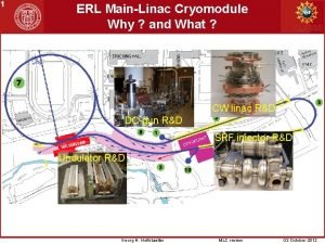
INTERNATIONAL ERL CRYOMODULE A. Wheelhouse ASTe. C, STFC Daresbury Laboratory TTC Topical Workshop - CW SRF, Cornell 12 th – 14 th June 2013 On behalf of ERL Cryomodule Collaboration

Outline • • • Project Overview Installation Cryogenic Commissioning Low Level RF Tests Future Plans ALICE 14 th June 2013 TTC Workshop A Wheelhouse

SRF Cryomodule • International collaboration initiated in early 2006: – – – – Original Cryomodule on ALICE ASTe. C (STFC) Cornell University DESY FZD-Rossendorf LBNL Stanford University TRIUMF (2009) • Fabricate new cryomodule and validate with beam. • Dimensioned to fit on ALICE: – Same CM footprint – Same cryo/RF interconnects – ‘Plug Compatible’ New ERL Cryomodule 14 th June 2013 TTC Workshop A Wheelhouse

SRF Cryomodule Parameter ALICE Target 1. 3 Number of cavities 2 2 Number of Cells per Cavity 9 7 1. 038 0. 807 3. 6 1036 762 12 - 15 >20 27 >32 Qo <5 x 10⁹ >1 x 10¹⁰ Qext 4 x 10⁶ – 108 Max Cavity Fwd Power (k. W) 10 SW 20 SW Frequency (GHz) Cavity Length (m) Cryomodule Length (m) Original Cryomodule on ALICE R/Q (Ω) Eacc (MV/m) CM Energy Gain (Me. V) New ERL Cryomodule 14 th June 2013 TTC Workshop A Wheelhouse

Major Variations in the Design 80 K-5 K-2 K 2 K-5 K-80 K 1. High power input couplers 2. Saclay II tuners 3. HOM absorbers 4. Several thermal transitions 2 K 5 K 80 K 14 th June 2013 TTC Workshop A Wheelhouse

Major Variations in the Design 5. Radiation shield, HOMs and thermal intercepts cooled with GHe 6. Additional thermal management scheme 7. Additional instrumentation 14 th June 2013 TTC Workshop A Wheelhouse

Installation on ALICE 14 th June 2013 TTC Workshop A Wheelhouse

Cryogenic System 2 K Box Preliminary cool down • • Dewar Cryomodule cooled to 2 K Static heat load measured at 2 K~ 6 W • • TCF 50 Base heat load measured at 2 K ~ 2. 5 g/s • • COOL-IT Gas pressure ~ 2 bar. A HOMs, coupler intercepts and thermal shield are connected in series • • • Similar to previous cryomodule Intermediate Temperatures has been achieved with GHe using COOL-IT • • Similar to previous cryomodule, Spec- 15 W Circuit 1: Tin ~ 89 K , Tout ~ 99 K Circuit 2: Tin ~ 13. 5 K , Tout ~ 15. 5 K Pressure stability at 2 K (30 mbar) ± 0. 05 mbar Ø Further optimisation is in progress Cryomodule 14 th June 2013 TTC Workshop A Wheelhouse

GHe Cooling Circuit 14 th June 2013 TTC Workshop A Wheelhouse

Cryogenic Performance COOL DOWN to 2 K 295 K 130 K Cryogenic (Pressure) Stability at 2 K 3 K/hr (Cooling only by radiation and conduction through supports) 2 ½ days to 130 K 15 hrs to 4 K Cavity 1 3 hrs to 2 K Cavity 2 2. 0 K Liquid Helium levels in Reservoirs Cavity 1 Cavity 2 Level Control Valve 14 th June 2013 Cavity 1 Cavity 2 Service Reservoir TTC Workshop A Wheelhouse

Static Heat Load at 2 K • Static heat load measured with all the input valves closed to ensure that only the boil off from the cryostat is measured • 0. 6 g/S total mass flow Linac + Booster a 0. 3 g/S per module a ~6. 2 W per cryomodule 14 th June 2013 TTC Workshop A Wheelhouse

Linac 1 • • Cavity Frequency Linac 2 Cavity tuner operation verified Tuning achieved Tuning range ± 350 k. Hz Qext adjusted • Previous mechanical issue Full extent of adjustment to be determined 14 th June 2013 TTC Workshop A Wheelhouse

Microphonic Tests Original Linac New ERL Linac • • The microphonics were tested in CW mode, open loop operation. Cavity was driven by signal generator A Hittite phase detector was used to measure the phase difference between the cavity probe signal and the system generator signal. • The new ERL cavities were driven with a CW wave from the digital LLRF system. The cavity probe signal is then mixed with the forward RF signal and filtered by a low pass filter. The cavities have been analysed in self excited loop and open loop operations. Based on the LLRF 4 development board, designed by Larry Doolittle of LBNL 14 th June 2013 TTC Workshop A Wheelhouse

Linac Cavity 1 • Detuning peaks at 48 Hz, 70 Hz, 34 Hz 14 th June 2013 TTC Workshop Open loop measurement, strong detuning peaks at: a 1 Hz, 7 Hz, 24 Hz, 35 Hz, 38 Hz, 47 Hz, 78 Hz, etc • Loop closed, the overall noise floor is lower and many detuning peaks removed. a 50 Hz resonance and its sidebands remain on the spectrum, which is common in background environment. A Wheelhouse

Linac Cavity 2 • Open loop operation, strong resonances have been observed at: a 1 Hz, 7 Hz , 21. 5 Hz, 23. 5 Hz, 35 Hz, 48 Hz, 68 Hz, 71 Hz, 78 Hz, 82 Hz, 98 Hz, etc. • Loop closed, resonances remain at 1 Hz, 37. 5 Hz, 50 Hz and its side bands. Detuning peaks at 22 Hz, 70 Hz, 63 Hz, 139 Hz, 386 Hz. 14 th June 2013 TTC Workshop A Wheelhouse

Future Plan Evaluation Programme: • Establish gradient and Q 0 • Measure Lorentz force detuning at high gradient • Performance measurements with piezo tuners • Determine DLLRF control limitations wrt Qext • Evaluate the effect of beam loading with DLLRF, piezo control for various Qext levels under pulsed and CW Cryomodule installed on ALICE conditions • Characterise cavities in CW mode at high gradient: – Evaluate thermal transients across cavity string and 2 -phase line 14 th June 2013 TTC Workshop A Wheelhouse
