
ERL Design Concepts DIANA DICE Peter Williams ASTe

- Slides: 21
ERL Design Concepts: DIANA & DICE Peter Williams ASTe. C, Daresbury Laboratory & Cockcroft Institute, UK Electrons for the LHC: Workshop on the LHe. C, FCC -eh and PERLE, Chavannes de Bogis 24 th October 2019
Energy Recovery Linacs - Required for LHe. C – Also Has Utility Beyond High Energy Particle Physics = Light Sources & Nuclear Physics 1. Free Electron Laser at High Average Power 2. High Flux, Narrowband Gamma Source based on Inverse Compton Scattering 3. High Luminosity Internal Target Particle / Nuclear Physics Experiments … Leading to common interest in LHe. C and PERLE from other fields, resulting in the developing proposals…. DIANA at Daresbury Laboratory, UK … ~ 1 Ge. V, ~ 50 m. A, multipass, separate transport ERL and DICE at TU Darmstadt, Germany …. ~ 400 Me. V, ~ 10 m. A, multipass, separate transport ERL Both proposals assume use of 802 MHz cryomodule under development for LHe. C / PERLE
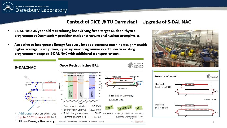
Context of DICE @ TU Darmstadt – Upgrade of S-DALINAC • S-DALINAC: 30 year old recirculating linac driving fixed target Nuclear Physics programme at Darmstadt – precision nuclear structure and nuclear astrophysics • Attractive to incorporate Energy Recovery into replacement machine design – enable higher average beam power, open up new programme in addition to existing programme – adapted S-DALINAC with additional transport to test… 3
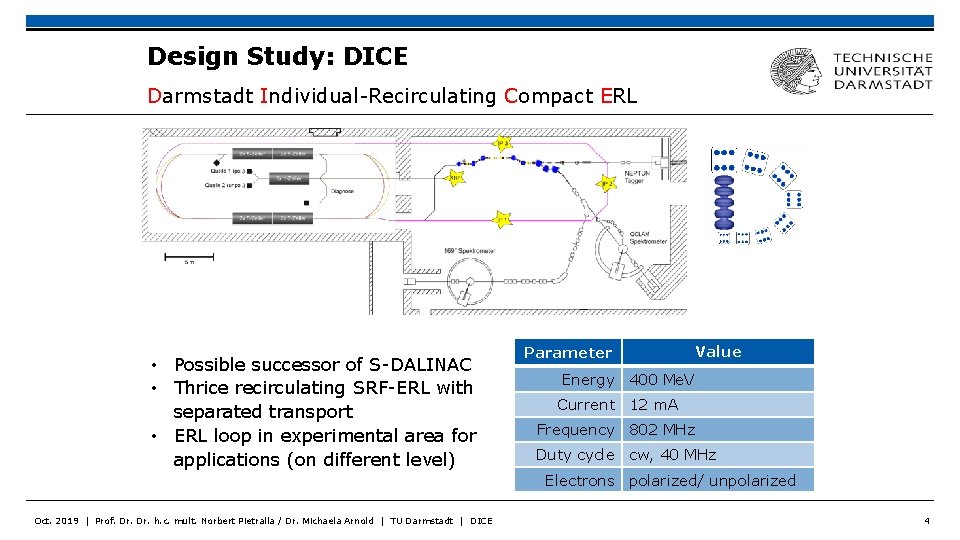
Design Study: DICE Darmstadt Individual-Recirculating Compact ERL • Possible successor of S-DALINAC • Thrice recirculating SRF-ERL with separated transport • ERL loop in experimental area for applications (on different level) Parameter Value Energy 400 Me. V Current 12 m. A Frequency 802 MHz Duty cycle cw, 40 MHz Electrons polarized/ unpolarized Oct. 2019 | Prof. Dr. h. c. mult. Norbert Pietralla / Dr. Michaela Arnold | TU Darmstadt | DICE 4
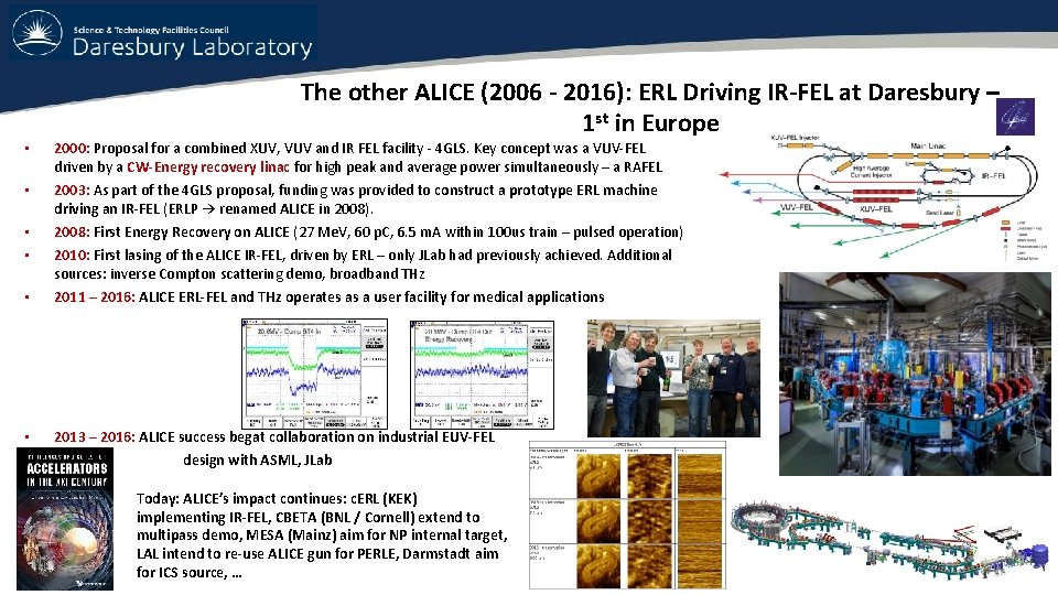
The other ALICE (2006 - 2016): ERL Driving IR-FEL at Daresbury – 1 st in Europe • 2000: Proposal for a combined XUV, VUV and IR FEL facility - 4 GLS. Key concept was a VUV-FEL driven by a CW-Energy recovery linac for high peak and average power simultaneously – a RAFEL • 2003: As part of the 4 GLS proposal, funding was provided to construct a prototype ERL machine driving an IR-FEL (ERLP → renamed ALICE in 2008). • • 2008: First Energy Recovery on ALICE (27 Me. V, 60 p. C, 6. 5 m. A within 100 us train – pulsed operation) • 2011 – 2016: ALICE ERL-FEL and THz operates as a user facility for medical applications • 2013 – 2016: ALICE success begat collaboration on industrial EUV-FEL 2010: First lasing of the ALICE IR-FEL, driven by ERL – only JLab had previously achieved. Additional sources: inverse Compton scattering demo, broadband THz design with ASML, JLab Today: ALICE’s impact continues: c. ERL (KEK) implementing IR-FEL, CBETA (BNL / Cornell) extend to multipass demo, MESA (Mainz) aim for NP internal target, LAL intend to re-use ALICE gun for PERLE, Darmstadt aim for ICS source, …
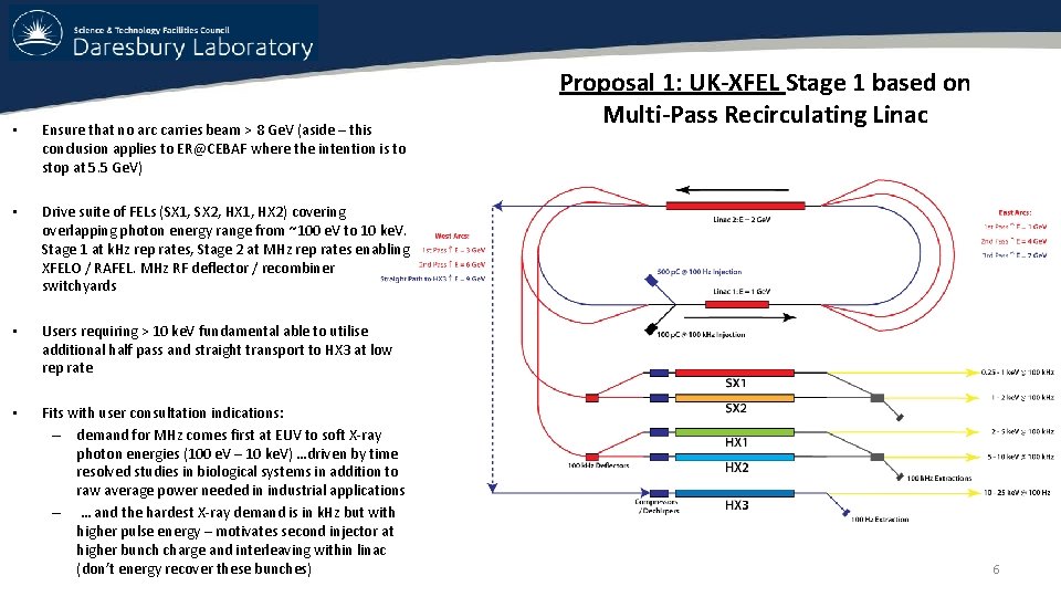
• Ensure that no arc carries beam > 8 Ge. V (aside – this conclusion applies to ER@CEBAF where the intention is to stop at 5. 5 Ge. V) • Drive suite of FELs (SX 1, SX 2, HX 1, HX 2) covering overlapping photon energy range from ~100 e. V to 10 ke. V. Stage 1 at k. Hz rep rates, Stage 2 at MHz rep rates enabling XFELO / RAFEL. MHz RF deflector / recombiner switchyards • Users requiring > 10 ke. V fundamental able to utilise additional half pass and straight transport to HX 3 at low rep rate • Fits with user consultation indications: – demand for MHz comes first at EUV to soft X-ray photon energies (100 e. V – 10 ke. V) …driven by time resolved studies in biological systems in addition to raw average power needed in industrial applications – … and the hardest X-ray demand is in k. Hz but with higher pulse energy – motivates second injector at higher bunch charge and interleaving within linac (don’t energy recover these bunches) Proposal 1: UK-XFEL Stage 1 based on Multi-Pass Recirculating Linac 6
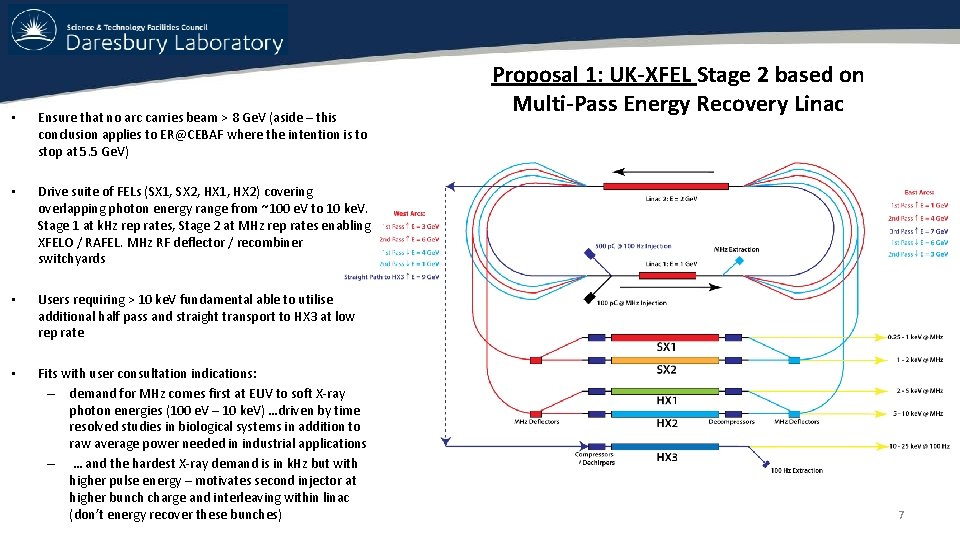
• Ensure that no arc carries beam > 8 Ge. V (aside – this conclusion applies to ER@CEBAF where the intention is to stop at 5. 5 Ge. V) • Drive suite of FELs (SX 1, SX 2, HX 1, HX 2) covering overlapping photon energy range from ~100 e. V to 10 ke. V. Stage 1 at k. Hz rep rates, Stage 2 at MHz rep rates enabling XFELO / RAFEL. MHz RF deflector / recombiner switchyards • Users requiring > 10 ke. V fundamental able to utilise additional half pass and straight transport to HX 3 at low rep rate • Fits with user consultation indications: – demand for MHz comes first at EUV to soft X-ray photon energies (100 e. V – 10 ke. V) …driven by time resolved studies in biological systems in addition to raw average power needed in industrial applications – … and the hardest X-ray demand is in k. Hz but with higher pulse energy – motivates second injector at higher bunch charge and interleaving within linac (don’t energy recover these bunches) Proposal 1: UK-XFEL Stage 2 based on Multi-Pass Energy Recovery Linac 7
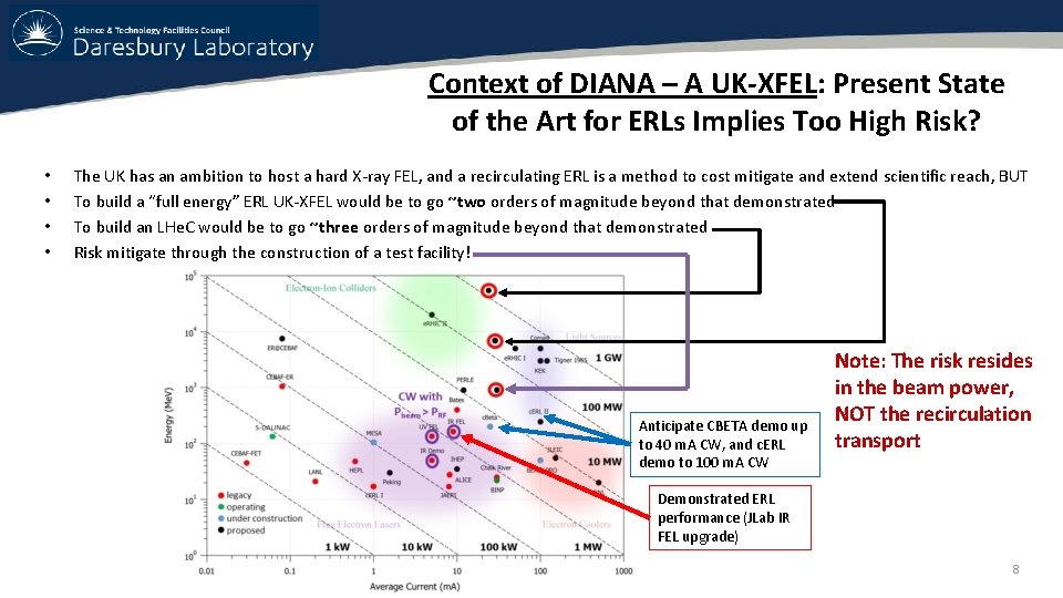
Context of DIANA – A UK-XFEL: Present State of the Art for ERLs Implies Too High Risk? • • The UK has an ambition to host a hard X-ray FEL, and a recirculating ERL is a method to cost mitigate and extend scientific reach, BUT To build a “full energy” ERL UK-XFEL would be to go ~two orders of magnitude beyond that demonstrated To build an LHe. C would be to go ~three orders of magnitude beyond that demonstrated Risk mitigate through the construction of a test facility! Anticipate CBETA demo up to 40 m. A CW, and c. ERL demo to 100 m. A CW Note: The risk resides in the beam power, NOT the recirculation transport Demonstrated ERL performance (JLab IR FEL upgrade) 8
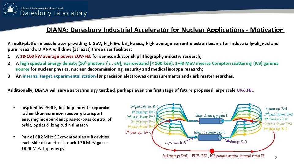
DIANA: Daresbury Industrial Accelerator for Nuclear Applications - Motivation A multi-platform accelerator providing 1 Ge. V, high 6 -d brightness, high average current electron beams for industrially-aligned and pure research. DIANA will drive (at least) three user facilities: 1. A 10 -100 k. W average power EUV-FEL for semiconductor chip lithography industry research; 2. A high spectral energy density (106 photons / s. e. V), narrowband (< 100 ke. V), 1 -40 Me. V inverse Compton scattering (ICS) gamma source for nuclear physics, nuclear decommissioning, security and medical isotope research; 3. An internal target experimental station for precision electroweak measurements and dark matter searches. Additionally, DIANA will serve as technology testbed, perhaps even the first stage of future proposed large scale UK-XFEL • • Inspired by PERLE, but implements separate rather than common recovery transport ensuring independent pass-to-pass control of orbit, optics & longitudinal match Pair of 802 MHz SC cryomodules = 8 cavities each side of racetrack, each 170 Me. V gain = 1020 Me. V top energy. 3 rd pass down: E=1 1 st pass up: E=2 2 nd pass down: E=3 2 nd pass up: E=4 1 st pass down: E=5 3 rd pass up: E= 6 1 st pass up: E=1 2 nd pass down: E=2 2 nd pass up: E=3 1 st pass down: E=4 3 rd pass up: E=5 linac 2: energy gain 1 linac 1: energy gain 1 injection: E~0 dump: E~0 full energy (E=6) – EUV- FEL, ICS gamma source, internal target IP 9
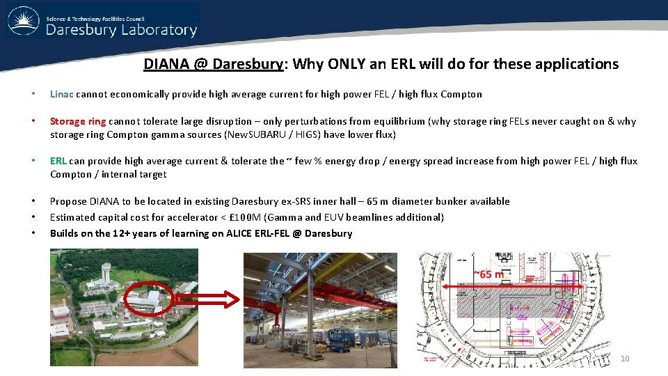
DIANA @ Daresbury: Why ONLY an ERL will do for these applications • Linac cannot economically provide high average current for high power FEL / high flux Compton • Storage ring cannot tolerate large disruption – only perturbations from equilibrium (why storage ring FELs never caught on & why storage ring Compton gamma sources (New. SUBARU / HIGS) have lower flux) • ERL can provide high average current & tolerate the ~ few % energy drop / energy spread increase from high power FEL / high flux Compton / internal target • • • Propose DIANA to be located in existing Daresbury ex-SRS inner hall – 65 m diameter bunker available Estimated capital cost for accelerator < £ 100 M (Gamma and EUV beamlines additional) Builds on the 12+ years of learning on ALICE ERL-FEL @ Daresbury 10
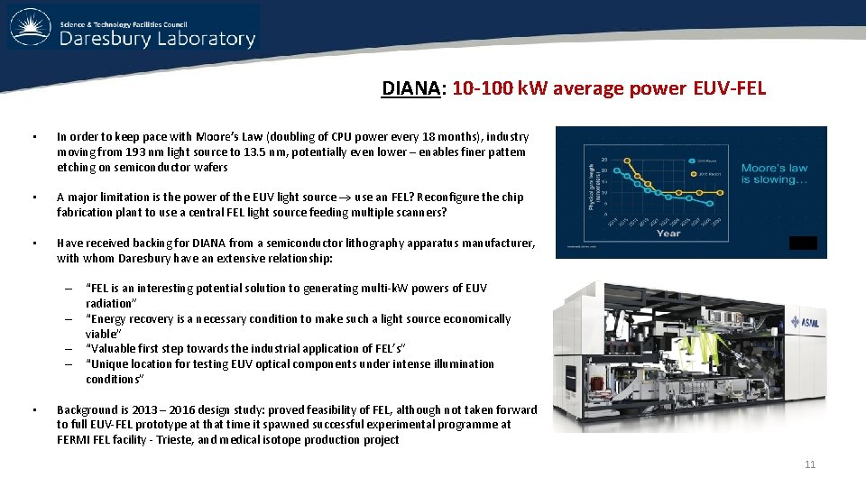
DIANA: 10 -100 k. W average power EUV-FEL • In order to keep pace with Moore’s Law (doubling of CPU power every 18 months), industry moving from 193 nm light source to 13. 5 nm, potentially even lower – enables finer pattern etching on semiconductor wafers • A major limitation is the power of the EUV light source use an FEL? Reconfigure the chip fabrication plant to use a central FEL light source feeding multiple scanners? • Have received backing for DIANA from a semiconductor lithography apparatus manufacturer, with whom Daresbury have an extensive relationship: – “FEL is an interesting potential solution to generating multi-k. W powers of EUV radiation” – “Energy recovery is a necessary condition to make such a light source economically viable” – “Valuable first step towards the industrial application of FEL’s” – “Unique location for testing EUV optical components under intense illumination conditions” • Background is 2013 – 2016 design study: proved feasibility of FEL, although not taken forward to full EUV-FEL prototype at that time it spawned successful experimental programme at FERMI FEL facility - Trieste, and medical isotope production project 11
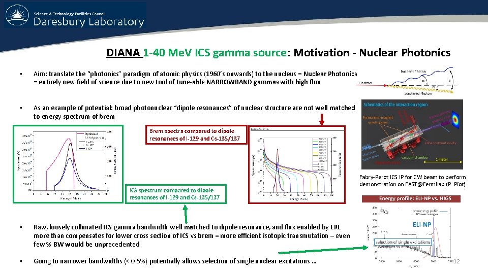
DIANA 1 -40 Me. V ICS gamma source: Motivation - Nuclear Photonics • Aim: translate the “photonics” paradigm of atomic physics (1960’s onwards) to the nucleus = Nuclear Photonics = entirely new field of science due to new tool of tune-able NARROWBAND gammas with high flux • As an example of potential: broad photonuclear “dipole resonances” of nuclear structure are not well matched to energy spectrum of brem Brem spectra compared to dipole resonances of I-129 and Cs-135/137 ICS spectrum compared to dipole resonances of I-129 and Cs-135/137 • Raw, loosely collimated ICS gamma bandwidth well matched to dipole resonance, and flux enabled by ERL more than compensates for lower cross section of ICS vs brem = more efficient isotopic transmutation – even few % BW would be unprecedented • Going to narrower bandwidths (< 0. 5%) potentially allows selection of single nuclear excitations … Fabry-Perot ICS IP for CW beam to perform demonstration on FAST@Fermilab (P. Piot) 12
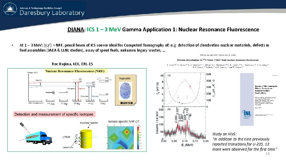
DIANA: ICS 1 – 3 Me. V Gamma Application 1: Nuclear Resonance Fluorescence • At 1 – 3 Me. V: ( , ’) = NRF, pencil beam of ICS source ideal for Computed Tomography of: e. g. detection of clandestine nuclear materials, defects in fuel assemblies (JAEA & LLNL studies), assay of spent fuels, unknown legacy wastes, … Roc Hajima, KEK, ERL-15 Study on HI S: “In addition to the nine previously reported transitions for U-235, 13 more were observed for the first time” 13
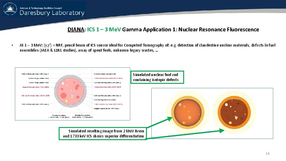
DIANA: ICS 1 – 3 Me. V Gamma Application 1: Nuclear Resonance Fluorescence • At 1 – 3 Me. V: ( , ’) = NRF, pencil beam of ICS source ideal for Computed Tomography of: e. g. detection of clandestine nuclear materials, defects in fuel assemblies (JAEA & LLNL studies), assay of spent fuels, unknown legacy wastes, … Simulated nuclear fuel rod containing isotopic defects Simulated resulting image from 2 Me. V Brem and 1733 ke. V ICS shows superior differentiation 14
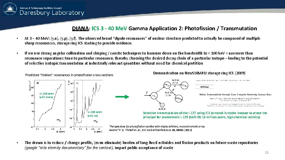
DIANA: ICS 3 - 40 Me. V Gamma Application 2: Photofission / Transmutation • At 3 – 40 Me. V: ( , n), ( , p), ( , f). The observed broad “dipole resonances” of nuclear structure predicted to actually be composed of multiple sharp resonances, storage ring ICS starting to provide evidence. • If we use strong angular collimation and chirping / caustic techniques to hammer down on the bandwidth to < 100 ke. V = narrower than resonance separations: tune to particular resonance, thereby choosing the desired decay chain of a particular isotope – leading to the potential of selective isotopic transmutation at industrially relevant quantities without need for chemical partition Predicted “hidden” resonances in photofission cross sections Demonstration on New. SUBARU storage ring ICS (2009) U-238 seen with Brem U-238 seen with ICS Selective transmutation of the I-127 using ICS (a stand-in stable isotope to prove the principal for problematic I-129 (half-life 16 million years, high chemical activity) “Perspectives for photofission studies with highly brilliant, monochromatic -ray beams” P. G. Thirolf et. al. , EPJ Web of Conferences 38, 08001 (2012) • The dream is to reduce / change profile, (even eliminate) burden of long-lived actinides and fission products on future waste repositories (google “into eternity documentary” for the context), impact public acceptance of waste 15
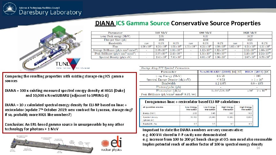
DIANA ICS Gamma Source Conservative Source Properties Comparing the resulting properties with existing storage-ring ICS gamma sources DIANA = 100 x existing measured spectral energy density at HIGS (Duke) and 10, 000 x New. SUBARU (adjacent to SPRING-8) DIANA = 10 x calculated spectral energy density for ELI-NP based on linac + recirculator (update 7 th October 2019: new contract for Lyncean, storage ring? If so, probably more HIGS like numbers? ) Conclusion: An ERL-based gamma source in unsurpassable by any other technology for photons > 1 Me. V Eurogammas linac + recirculator based ELI-NP calculations Important to state the DIANA numbers are very conservative: e. g. 400 k. W stored in F-P cavity now demonstrated e. g. increase from 100 to 200 p. C bunch charge at 0. 5 mm mrad also reasonable Implies potential reach of another factor of 100 in spectral energy density 16
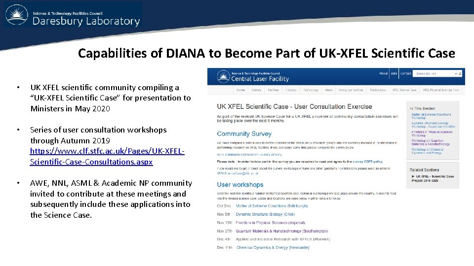
Capabilities of DIANA to Become Part of UK-XFEL Scientific Case • UK XFEL scientific community compiling a “UK-XFEL Scientific Case” for presentation to Ministers in May 2020 • Series of user consultation workshops through Autumn 2019 https: //www. clf. stfc. ac. uk/Pages/UK-XFELScientific-Case-Consultations. aspx • AWE, NNL, ASML & Academic NP community invited to contribute at these meetings and subsequently include these applications into the Science Case.
Conclusion: Motivation & Strategies to Develop DIANA & DICE Proposals Motivation for DICE@Darmstadt: • Drive existing NP experiments as replacement for S-DALINAC due to aging • Enable future ICS source + other applications • Accelerator research and training of students Motivation for DIANA@Daresbury: • Standalone industrial applications focused – high power EUV-FEL & ICS gamma source + others • Prototype, perhaps even first stage of larger UK-XFEL machine • • Funding for DICE being sought at Federal & State level in Germany on the principle of matching funds Funding for DIANA initially embedded within UK Research & Innovation UK-XFEL R&D, developing collaborative work with nuclear security and civil power research institutes, together with semiconductor industry • These differences in goals account for the different approaches, though all derived from the common platform of a multipass SC-ERL capable of 10’s m. A CW utilising 802 MHz RF. This is the reason why DIANA / DICE will not be copies of PERLE, but require their own bespoke design.
Extra Slides
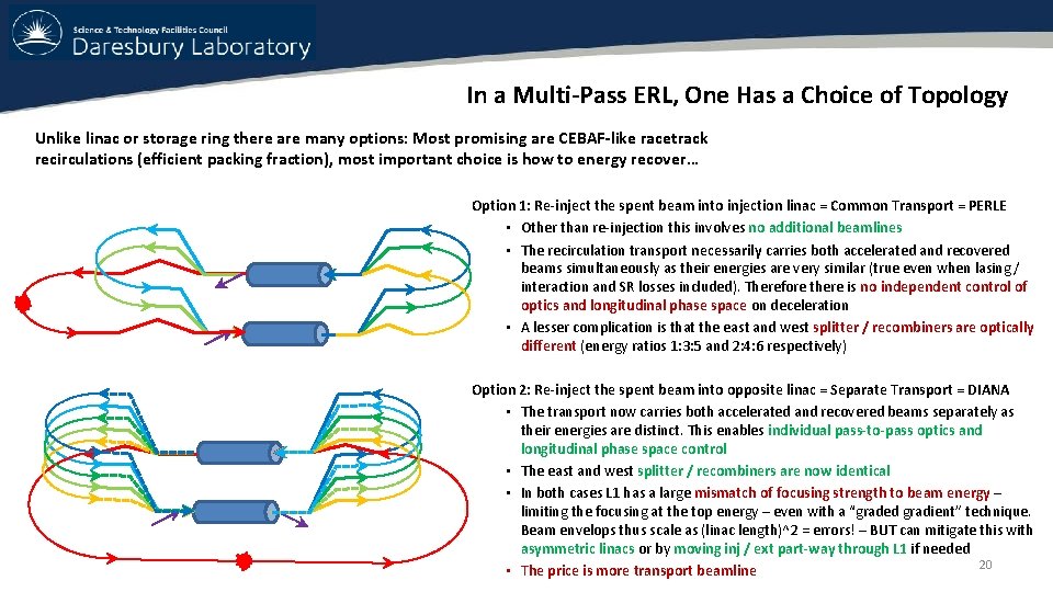
In a Multi-Pass ERL, One Has a Choice of Topology Unlike linac or storage ring there are many options: Most promising are CEBAF-like racetrack recirculations (efficient packing fraction), most important choice is how to energy recover… Option 1: Re-inject the spent beam into injection linac = Common Transport = PERLE • Other than re-injection this involves no additional beamlines • The recirculation transport necessarily carries both accelerated and recovered beams simultaneously as their energies are very similar (true even when lasing / interaction and SR losses included). Therefore there is no independent control of optics and longitudinal phase space on deceleration • A lesser complication is that the east and west splitter / recombiners are optically different (energy ratios 1: 3: 5 and 2: 4: 6 respectively) Option 2: Re-inject the spent beam into opposite linac = Separate Transport = DIANA • The transport now carries both accelerated and recovered beams separately as their energies are distinct. This enables individual pass-to-pass optics and longitudinal phase space control • The east and west splitter / recombiners are now identical • In both cases L 1 has a large mismatch of focusing strength to beam energy – limiting the focusing at the top energy – even with a “graded gradient” technique. Beam envelops thus scale as (linac length)^2 = errors! – BUT can mitigate this with asymmetric linacs or by moving inj / ext part-way through L 1 if needed 20 • The price is more transport beamline
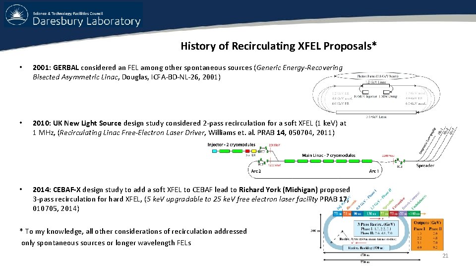
History of Recirculating XFEL Proposals* • 2001: GERBAL considered an FEL among other spontaneous sources (Generic Energy-Recovering Bisected Asymmetric Linac, Douglas, ICFA-BD-NL-26, 2001) • 2010: UK New Light Source design study considered 2 -pass recirculation for a soft XFEL (1 ke. V) at 1 MHz, (Recirculating Linac Free-Electron Laser Driver, Williams et. al. PRAB 14, 050704, 2011) • 2014: CEBAF-X design study to add a soft XFEL to CEBAF lead to Richard York (Michigan) proposed 3 -pass recirculation for hard XFEL, (5 ke. V upgradable to 25 ke. V free electron laser facility PRAB 17, 010705, 2014) * To my knowledge, all other considerations of recirculation addressed only spontaneous sources or longer wavelength FELs 21