Chapter 29 Transistor Amplifiers Use of Capacitors in




- Slides: 42
Chapter 29 Transistor Amplifiers
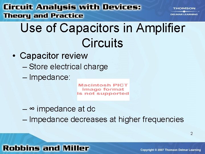
Use of Capacitors in Amplifier Circuits • Capacitor review – Store electrical charge – Impedance: – ∞ impedance at dc – Impedance decreases at higher frequencies 2
Use of Capacitors in Amplifier Circuits • Capacitors – Block dc between stages – Can be designed to readily pass ac 3
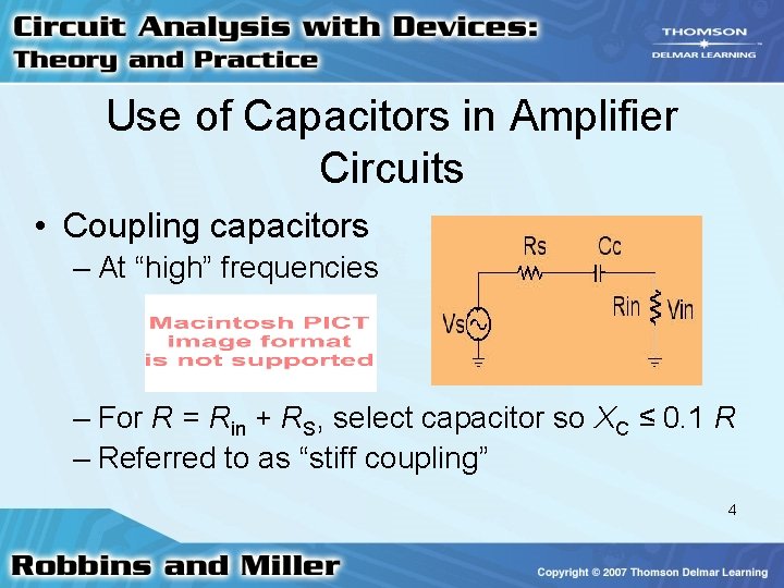
Use of Capacitors in Amplifier Circuits • Coupling capacitors – At “high” frequencies – For R = Rin + RS, select capacitor so XC ≤ 0. 1 R – Referred to as “stiff coupling” 4
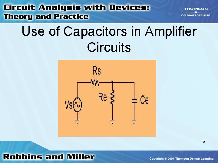
Use of Capacitors in Amplifier Circuits • Bypass capacitors – Emitter resistor, Re used for biasing – Ce is a short circuit at high frequencies – Re has no effect on amplification when Ce is present – Select XC ≤ 0. 1 R 5
Use of Capacitors in Amplifier Circuits 6
Use of Capacitors in Amplifier Circuits • Capacitors – Couple desired ac signals between stages – Bypass unwanted ac signals to ground 7
Use of Capacitors in Amplifier Circuits • Circuit analysis – If XC ≤ 0. 1 R – Replace C with O. C. to determine dc I and V – Replace C with S. C. to determine ac i and v 8
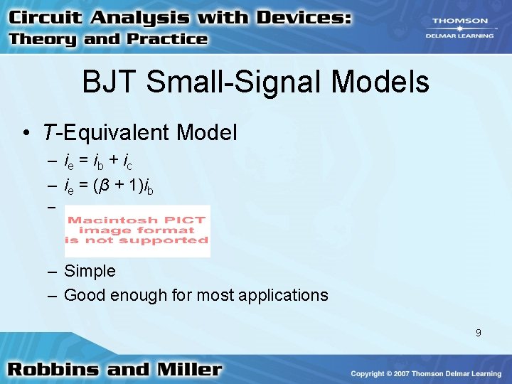
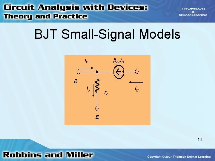
BJT Small-Signal Models • T-Equivalent Model – ie = i b + i c – ie = (β + 1)ib – – Simple – Good enough for most applications 9
BJT Small-Signal Models ib βacib B ie rc i. C E 10
BJT Small-Signal Models • Models – T-equivalent model simpler – h-parameter model more accurate – hfe (h-model) = βac (T-model) [βac ≈ βdc] – h-parameters dependent on Q-point – BJT is a current amplifier (current source in both models) 11
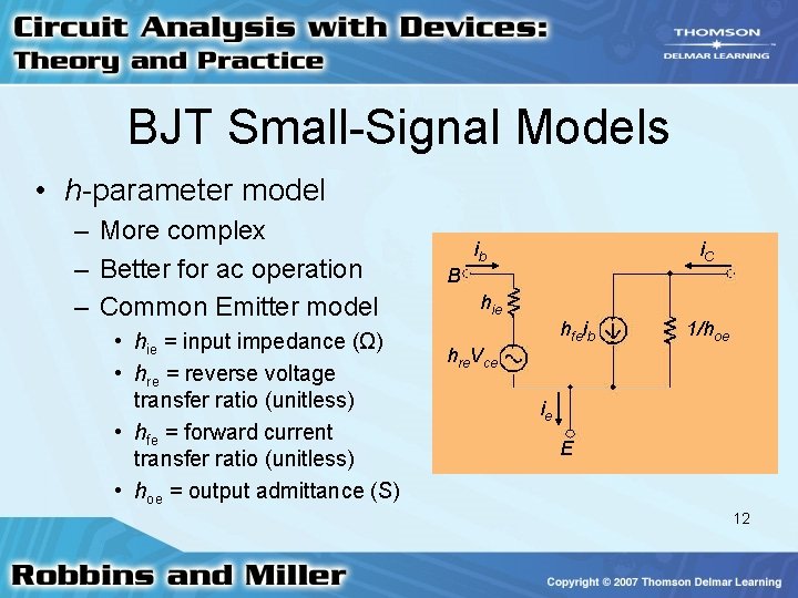
BJT Small-Signal Models • h-parameter model – More complex – Better for ac operation – Common Emitter model • hie = input impedance (Ω) • hre = reverse voltage transfer ratio (unitless) • hfe = forward current transfer ratio (unitless) • hoe = output admittance (S) ib i. C B hie hfeib 1/hoe hre. Vce ie E 12
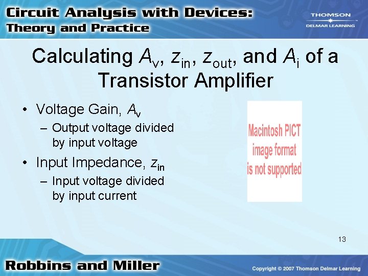
Calculating Av, zin, zout, and Ai of a Transistor Amplifier • Voltage Gain, Av – Output voltage divided by input voltage • Input Impedance, zin – Input voltage divided by input current 13
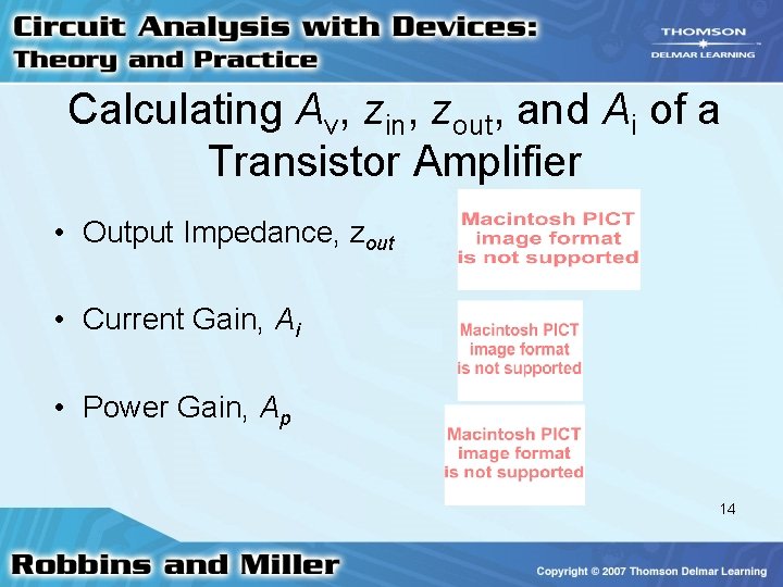
Calculating Av, zin, zout, and Ai of a Transistor Amplifier • Output Impedance, zout • Current Gain, Ai • Power Gain, Ap 14
Common-Emitter Amplifier • General BJT circuit analysis – Find operating point – Determine ac parameters (T- or h- models) – Remove dc V sources & replace with S. C. ’s – Replace coupling & bypass C’s with S. C. ’s – Replace BJT with circuit model – Solve resulting circuit 15
Common-Emitter Amplifier • ac equivalent of fixed-bias CE amplifier using h-parameter model 16
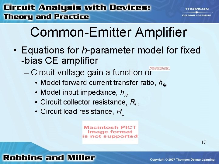
Common-Emitter Amplifier • Equations for h-parameter model for fixed -bias CE amplifier – Circuit voltage gain a function of • • Model forward current transfer ratio, hfe Model input impedance, hie Circuit collector resistance, RC Circuit load resistance, RL 17
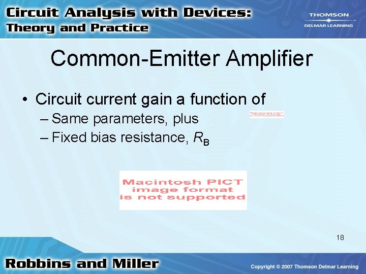
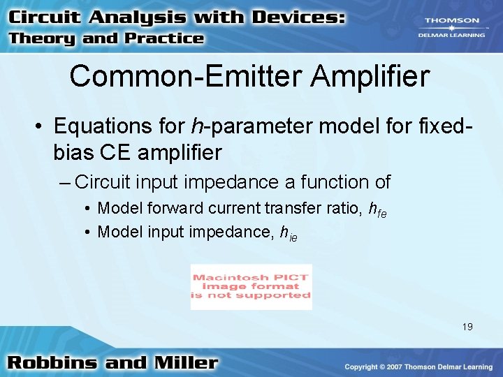
Common-Emitter Amplifier • Circuit current gain a function of – Same parameters, plus – Fixed bias resistance, RB 18
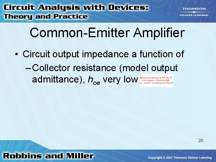
Common-Emitter Amplifier • Equations for h-parameter model for fixedbias CE amplifier – Circuit input impedance a function of • Model forward current transfer ratio, hfe • Model input impedance, hie 19
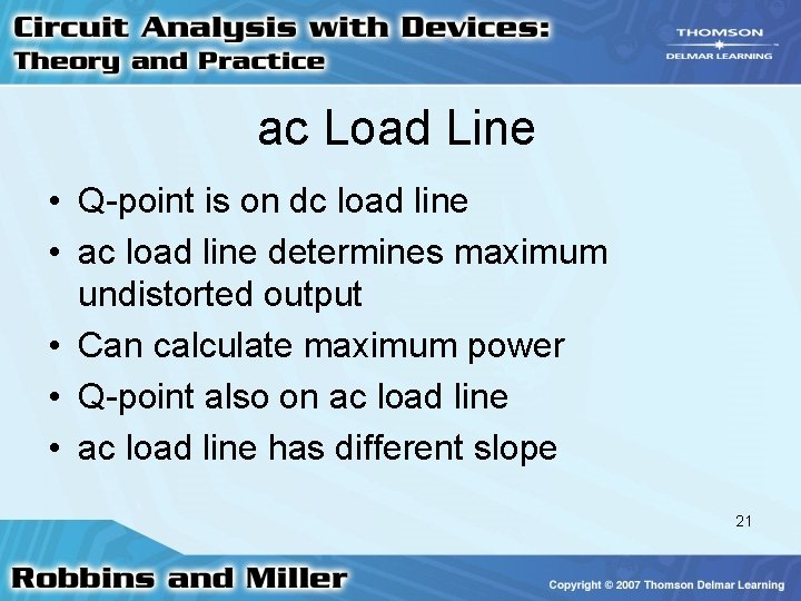
Common-Emitter Amplifier • Circuit output impedance a function of – Collector resistance (model output admittance), hoe very low 20
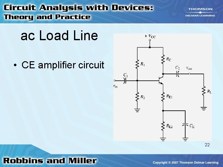
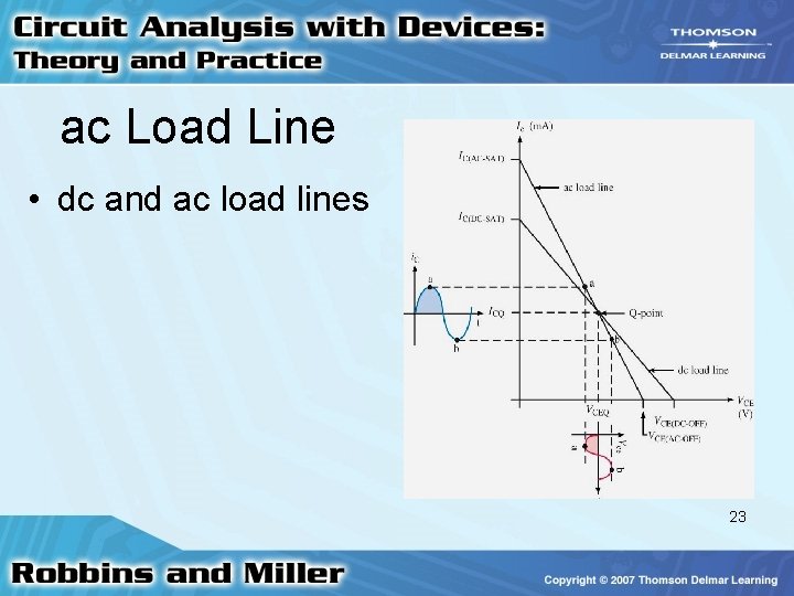
ac Load Line • Q-point is on dc load line • ac load line determines maximum undistorted output • Can calculate maximum power • Q-point also on ac load line • ac load line has different slope 21
ac Load Line • CE amplifier circuit 22
ac Load Line • dc and ac load lines 23
ac Load Line • Equations of ac load line • Consider – CE amplifier circuit – dc load line 24
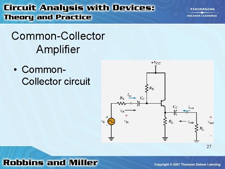
Common-Collector Amplifier • Important characteristics – High input impedance – Low output impedance – vout in-phase with vin – vout ≈ vin 25
Common-Collector Amplifier • Important characteristics – Large current gain – Input voltage measured at base – Output voltage measured at emitter 26
Common-Collector Amplifier • Common. Collector circuit 27
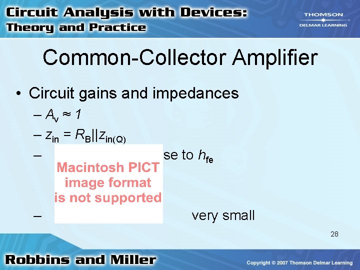
Common-Collector Amplifier • Circuit gains and impedances – Av ≈ 1 – zin = RB||zin(Q) – – close to hfe very small 28
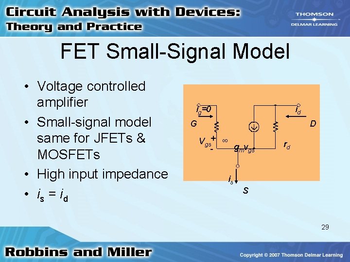
FET Small-Signal Model • Voltage controlled amplifier • Small-signal model same for JFETs & MOSFETs • High input impedance • is = i d ig=0 id G D Vgs+ ∞ gmvgs - rd is S 29
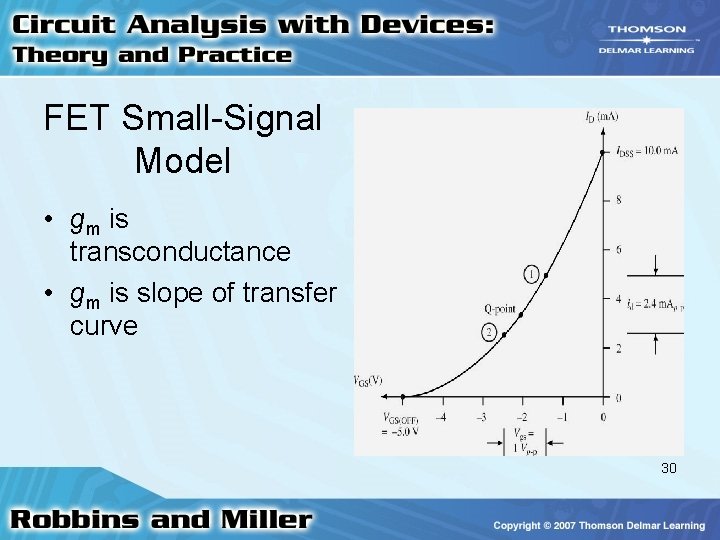
FET Small-Signal Model • gm is transconductance • gm is slope of transfer curve 30
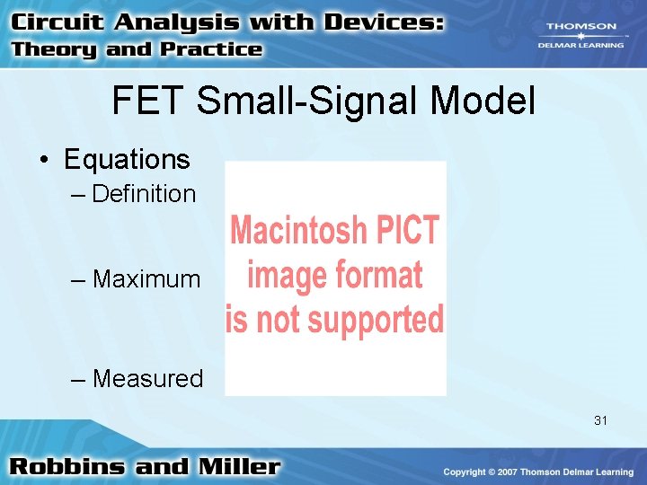
FET Small-Signal Model • Equations – Definition – Maximum – Measured 31
Common-Source Amplifier • Analysis – Similar to BJT using h-parameter model – First determine bias – Find dc operating point (Q-point) – Determine gm 32
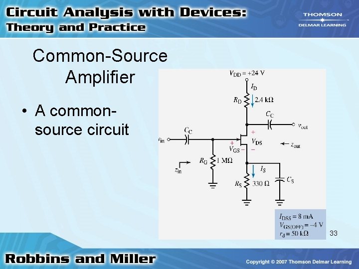
Common-Source Amplifier • A commonsource circuit 33
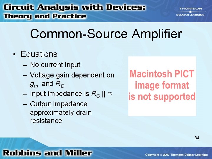
Common-Source Amplifier • Equations – No current input – Voltage gain dependent on gm and RD – Input impedance is RG || ∞ – Output impedance approximately drain resistance 34
Common-Source Amplifier • D-MOSFETs – Analysis same as JFETs – Except operation in enhancement region 35
Common-Source Amplifier • E-MOSFETs – Find IDSQ, VGSQ, and VDSQ at Q-point – Solve for gm of amplifier – Sketch ac equivalent circuit – Determine Av, zin, and zout of amplifier 36
Common-Drain (Source Follower) Amplifier • • • Av < 1 vout in phase with vin Input impedance very high Output impedance low Main application: Buffer 37
Troubleshooting a Transistor Amplifier Circuit • Incorrect placement of electrolytic capacitors – Noisy output signal – Capacitor as an antenna – Generally 60 Hz added 38
Troubleshooting a Transistor Amplifier Circuit • Correct placement – Check proper polarity – Replace faulty capacitors 39
Troubleshooting a Transistor Amplifier Circuit • Faulty or incorrectly placed capacitor – Measured Av different from theoretical Av – Faulty capacitor behaves like an open circuit – Faulty capacitor can develop internal short 40
Troubleshooting a Transistor Amplifier Circuit • Troubleshooting steps – Remove ac signal sources from circuit – Calculate theoretical Q-point – Measure to determine actual Q-point – Verify capacitors are correctly placed – Ensure connections, especially ground wires, as short as possible 41
Troubleshooting a Transistor Amplifier Circuit • Distorted output signal usually the result of too large an input signal 42