Voltage Regulators Power Supplies Voltage regulator keeps the


 If the output voltage tries to")


- Slides: 21
Voltage Regulators
Power Supplies
Voltage regulator • keeps the output voltage constant • in spite of changes in load current or input voltage. Factors Affecting the Load Voltage The load current (IL): The line voltage : The temperature
Power Supply Performance Parameters Load Regulation • The load regulation is denoted as LR • VNL = Load voltage with no load current • VFL = Load voltage with full load current Regulation characteristics 0%, which is the best expected
Question: • A dc voltage supply provides 60 V when the output is unloaded. When connected to a load, the output drops to 56 V. Calculate the value of voltage regulation. (load regulation)
Line Regulation or Source Regulation The SR is defined as the change in the regulated load voltage for a specified range of line voltage, VHL = load voltage with high line voltage VLL = load voltage with low line voltage Vnom = nominal load voltage
Question: • For a particular power supply, the load voltage is 10 V ± 0. 3 V for a line voltage of 230 V ± 10 %, calculate source regulation and percentage source regulation. • • VHL = 10 + 0. 3 = 10. 3 V VLL = 10 - 0. 3 = 9. 7 V SR = VHL - VLL = 10. 3 - 9. 7 = 0. 6 V Vnom= 10 V
DISCRETE TRANSISTOR VOLTAGE REGULATION 1. the series voltage regulator and 2. the shunt voltage regulator.
Series Voltage Regulation • If the output voltage increases, • the comparator circuit provides a control signal to cause the series control element to decrease the amount of the output voltage • If the output voltage decreases, • the comparator circuit provides a control signal to cause the series control element to increase the amount of the output voltage.
Emitter-follower Type Regulator Basic working Transistor Q 1 is the series control element, Zener diode DZ - the reference voltage. Ø If the output voltage decreases, Ø the increased VBE causes transistor Q 1 to conduct more, Ø thereby raising the output voltage Ø If the output voltage increases, Ø the decreased VBE causes transistor Q 1 to conduct less, Ø thereby reducing the output voltage
Emitter-follower Type Regulator
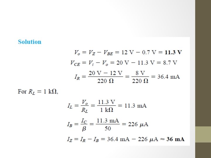
Question: • Calculate the output voltage and Zener current in the regulator circuit of Fig.
IMPROVED SERIES REGULATORCONTROLLED TRANSISTOR SERIES REGULATOR(NEGATIVE FEEDBACK REGULATOR) If the output voltage tries to increase, • increased voltage V 2, causes the VBE 2 up(since VZ remains fixed). • If Q 2 conducts more current, • less goes to the base of transistor Q 1, • which then passes less current to the load, reducing Vo • thereby maintaining the output voltage constant.
OVERLOAD PROTECTION – SHORT CIRCUIT PROTECTION • CURRENT LIMITING CIRCUIT • With transistor • With diodes Disadvantage : -large power dissipation in the series pass transistor
OVERLOAD PROTECTION – SHORT CIRCUIT PROTECTION • FOLDBACK CURRENT LIMITING
OVERLOAD PROTECTION – SHORT CIRCUIT PROTECTION • FOLDBACK CURRENT LIMITING
SHUNT VOLTAGE REGULATION • If the load voltage tries to change due to a change in the load, Ø the sampling circuit provides a feedback signal to a comparator, Ø which then provides a control signal to vary the amount of the current shunted away from the load.
BASIC TRANSISTOR SHUNT REGULATOR Ø If the load resistance decreases, Ø a reduced drive current to the base of Q 1 results, Ø shunting less collector current. Ø The load current is thus larger, thereby maintaining the regulated voltage across the load.
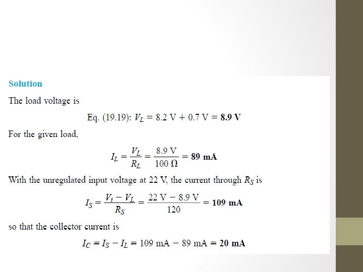
Question: • Determine the regulated voltage and circuit currents for the shunt regulator of Fig.