Chapter 2 HCS 12 Assembly Programming Three Sections

Chapter 2 HCS 12 Assembly Programming

Three Sections of a HCS 12/MC 9 S 12 Assembly Program • Assembler directives – – – Defines data and symbol Reserves and initializes memory locations Sets assembler and linking condition Specifies output format Specifies the end of a program • Assembly language instructions – HCS 12/MC 9 S 12 instructions • Comments – Explains the function of a single or a group of instructions

Fields of a HCS 12 Instruction • Label field – Optional – Starts with a letter and followed by letters, digits, or special symbols (_ or. ) – Can start from any column if ended with “: ” – Must start from column 1 if not ended with “: ” • Operation field – Contains the mnemonic of a machine instruction or an assembler directive – Separated from the label by at least one space • Operand field – Follows the operation field and is separated from the operation field by at least one space – Contains operands for instructions or arguments for assembler directives • Comment field – Any line starts with an * or ; is a comment – Separated from the operand operation field for at least one space – Optional

Identify the Four Fields of an Instruction Example loop ADDA #$40 ; add 40 to accumulator A (1) “loop” is a label (2) “ADDA” is an instruction mnemonic (3) “#$40” is the operand (4) “add #$40 to accumulator A” is a comment movb 0, X, 0, Y ; memory to memory copy (1) no label field (b) “movb” is an instruction mnemonic (c) “ 0, X, 0, Y” is the operand field (d) “; memory to memory copy” is a comment

Assembler Directives • END – Ends a program to be processed by an assembler – Any statement following the END directive is ignored. • ORG – The assembler uses a location counter to keep track of the memory location where the next machine code byte should be placed. – This directive sets a new value for the location counter of the assembler. – The sequence ORG $1000 LDAB #$FF places the opcode byte for the instruction LDAB #$FF at location $1000.
 db (define byte) fcb (form constant byte) - These")
dc. b (define constant byte) db (define byte) fcb (form constant byte) - These three directives define the value of a byte or bytes that will be placed at a given location. - These directives are often preceded by the org directive. - For example, org $800 array dc. b $11, $22, $33, $44 dc. w (define constant word) dw (define word) fdb (form double bytes) - Define the value of a word or words that will be placed at a given location. - The value can be specified by an expression. - For example, vec_tab dc. w $1234, abc-20
 • Used to define a string of characters (a message)")
fcc (form constant character) • Used to define a string of characters (a message) • The first character (and the last character) is used as the delimiter. • The last character must be the same as the first character. • The delimiter must not appear in the string. • The space character cannot be used as the delimiter. • Each character is represented by its ASCII code. • Example msg fcc “Please enter 1, 2 or 3: ”
 - This directive allows the user to fill a certain number")
fill (fill memory) - This directive allows the user to fill a certain number of memory locations with a given value. - The syntax is fill value, count - Example space_line fill $20, 40 ds (define storage) rmb (reserve memory byte) ds. b (define storage bytes) - Each of these directives reserves a number of bytes given as the arguments to the directive. - Example buffer ds 100 reserves 100 bytes
 rmw (reserve memory word) - Each of these directives")
ds. w (define storage word) rmw (reserve memory word) - Each of these directives increments the location counter by the value indicated in the number-of-words argument multiplied by two. - Example dbuf ds. w 20 reserves 40 bytes starting from the current location counter equ (equate) - This directive assigns a value to a label. - Using this directive makes one’s program more readable. - Examples arr_cnt equ 100 oc_cnt equ 50

loc - This directive increments and produces an internal counter used in conjunction with the backward tick mark (`). - By using the loc directive and the ` mark, one can write program segments like the following example, without thinking up new labels: loc ldaa #2 loop` deca same as loop 001 deca bne loop` bne loop 001 loc loop` brclr 0, x, $55, loop` loop 002 brclr 0, x, $55, loop 002

Macro - A name assigned to a group of instructions - Use macro and endm to define a macro. - Example of macro sum. Of 3 ldaa arg 1 adda arg 2 adda arg 3 endm macro arg 1, arg 2, arg 3 - Invoke a defined macro: write down the name and the arguments of the macro sum. Of 3 $1000, $1001, $1002 is replaced by ldaa $1000 adda $1001 adda $1002

Software Development Process • Problem definition: Identify what should be done. – Develop the algorithm. • Algorithm is the overall plan for solving the problem at hand. • An algorithm is often expressed in the following format: – – Step 1 … Step 2 … – Another way to express overall plan is to use flowchart. • Programming. Convert the algorithm or flowchart into programs. • Program testing • Program maintenance

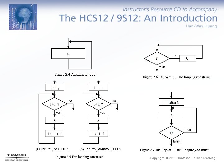
Symbols of Flowchart
 Example 2. 4 Write a program")
Programs to Do Simple Arithmetic (1 of 5) Example 2. 4 Write a program to add the values of memory locations at $1000, $1001, and $1002, and save the result at $1100. Solution: Step 1 A m[$1000] Step 2 A A + m[$1001] Step 3 A A + m[$1002] Step 4 $802 A org $1500 ldaa $1000 adda $1501 adda $1002 staa $1100 end
 Example 2. 4 Write a program")
Programs to Do Simple Arithmetic (2 of 5) Example 2. 4 Write a program to subtract the contents of the memory location at $1005 from the sum of the memory locations at $1000 and $1002, and store the difference at $1100. Solution: org $1500 ldaa $1000 adda $1002 suba $1005 staa $1000 end
 Example 2. 6 Write a program")
Programs to Do Simple Arithmetic (3 of 5) Example 2. 6 Write a program to add two 16 -bit numbers that are stored at $1000 -$1001 and $1002 -$1003 and store the sum at $1100 -$1101. Solution: org $1500 ldd $1000 addd$1002 std $1100 end The Carry Flag - bit 0 of the CCR register - set to 1 when the addition operation produces a carry 1 - set to 1 when the subtraction operation produces a borrow 1 - enables the user to implement multi-precision arithmetic
 Example 2. 7 Write a program")
Programs to Do Simple Arithmetic (4 of 5) Example 2. 7 Write a program to add two 4 -byte numbers that are stored at $1000 -$1003 and $1004 -$1007, and store the sum at $1010 -$1013. Solution: Addition starts from the LSB and proceeds toward MSB. org ldd addd std $1500 $1002 ; add and save the least significant two bytes $1006 ; “ $1012 ; “ ldaa adca staa $1001 ; add and save the second most significant bytes $1005 ; “ $1011 ; “ ldaa adca staa end $1000 ; add and save the most significant bytes $1004 ; “ $1010 ; “
 Example 2. 8 Write a program")
Programs to Do Simple Arithmetic (5 of 5) Example 2. 8 Write a program to subtract the hex number stored at $1004 -$1007 from the hex number stored at $1000 -$1003 and save the result at $1100$1103. Solution: The subtraction starts from the LSBs and proceeds toward the MSBs. org ldd subd std $1500 $1002 $1006 $1102 ; subtract and save the least significant two bytes ; “ ldaa sbca staa $1001 $1005 $1001 ; subtract and save the difference of the second to most ; significant bytes ; “ ldaa sbca staa end $1000 $1004 $1100 ; subtract and save the difference of the most significant ; bytes ; “

BCD Numbers and Addition • Each digit is encoded by 4 bits. • Two digits are packed into one byte • The addition of two BCD numbers is performed by binary addition and an adjust operation using the DAA instruction. • The instruction DAA can be applied after the instructions ADDA, ADCA, and ABA. • Simplifies I/O conversion • For example, the instruction sequence – LDAA $1000 – ADDA $1001 – DAA – STAA $1002 adds the BCD numbers stored at $1000 and $1001 and saves the sum at $1002.
")
Multiplication and Division (1 of 2)
 Example 2. 10 Write an instruction sequence to")
Multiplication and Division (2 of 2) Example 2. 10 Write an instruction sequence to multiply the 16 -bit numbers stored at $1000 -$1001 and $1002 -$1003 and store the product at $1100 -$1103. Solution: ldd ldy emul sty std $1000 $1002 $1100 $1102 Example 2. 11 Write an instruction sequence to divide the 16 -bit number stored at $1020 -$1021 into the 16 -bit number stored at $1005 -$1006 and store the quotient and remainder at $1100 and $1102, respectively. Solution: ldd ldx idiv stx std $1005 $1020 $1102 ; store the quotient ; store the remainder

Illustration of 32 -bit by 32 -bit Multiplication • Two 32 -bit numbers M and N are divided into two 16 -bit halves – M = MHML – N = NHNL

Example 2. 12 Write a program to multiply two unsigned 32 -bit numbers stored at M~M+3 and N~N+3, respectively and store the product at P~P+7. Solution: org $1000 M ds. b 4 N ds. b 4 P ds. b 8 org $1500 ldd M+2 ldy N+2 emul ; compute MLNL sty P+4 std P+6 ldd M ldy N emul ; compute MHNH sty P std P+2 ldd M ldy N+2 emul ; compute MHNL

; add MHNL to memory locations P+2~P+5 addd P+4 std P+4 tfr Y, D adcb P+3 stab P+3 adca P+2 staa P+2 ; propagate carry to the most significant byte ldaa P+1 adca #0 ; add carry to the location at P+1 staa P+1 ; “ ldaa P ; add carry to the location at P adca #0 ; “ staa P ; “ ; compute MLNH ldd M+2 ldy N emul

; add MLNH to memory locations P+2 ~ P+5 addd P+4 std P+4 tfr Y, D adcb P+3 stab P+3 adca P+2 staa P+2 ; propagate carry to the most significant byte clra adca P+1 staa P+1 ldaa P adca #0 staa P end

Example 2. 13 Write a program to convert the 16 -bit number stored at $1000 -$1001 to BCD format and store the result at $1010 -$1014. Convert each BCD digit into its ASCII code and store it in one byte. Solution: - A binary number can be converted to BCD format by using repeated division by 10. - The largest 16 -bit binary number is 65535 which has five decimal digits. - The first division by 10 generates the least significant digit, the second division by 10 obtains the second least significant digit, and so on. data result org dc. w org ds. b $1000 12345 $1010 5 org ldd ldy ldx idiv addb stab xgdx ldx $1500 data #result #10 #$30 4, Y #10 ; data to be tested ; reserve bytes to store the result ; convert the digit into ASCII code ; save the least significant digit

idiv adcb stab xgdx ldx idiv addb stab xgdx addb stab end #$30 3, Y ; save the second to least significant digit #10 #$30 2, Y ; save the middle digit #10 #$30 1, Y ; save the second most significant digit #$30 0, Y ; save the most significant digit

Program Loops • Types of program loops: finite and infinite loops • Looping mechanisms: – do statement S forever – For i = n 1 to n 2 do statement S or For i = n 2 downto n 1 do statement S – While C do statement S – Repeat statement S until C • Program loops are implemented by using the conditional branch instructions and the execution of these instructions depends on the contents of the CCR register.
 branch: always")
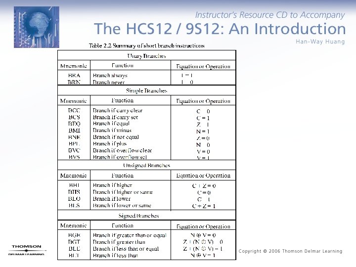
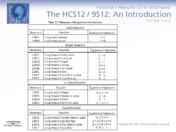
Condition Code Register • Four types of branch instructions – Unary (unconditional) branch: always execute – Simple branches: branch is taken when a specific bit of CCR is in a specific status – Unsigned branches: branches are taken when a comparison or test of unsigned numbers results in a specific combination of CCR bits – Signed branches: branches are taken when a comparison or test of signed quantities are in a specific combination of CCR bits • Two categories of branches – Short branches: in the range of -128 ~ +127 bytes – Long branches: in the range of 64 KB

Compare and Test Instructions • Condition flags need to be set up before conditional branch instruction should be executed. • The HCS 12 provides a group of instructions for testing the condition flags.

Loop Primitive Instructions • HCS 12 provides a group of instructions that either decrement or increment a loop count to determine if the looping should be continued. • The range of the branch is from $80 (-128) to $7 F (+127).

Example 2. 14 Write a program to add an array of N 8 -bit numbers and store the sum at memory locations $1000~$1001. Use the For i = n 1 to n 2 do looping construct. Solution: N sum i loop equ org rmb org ldaa staa ldab cmpb beq ldx abx ldab ldy aby sty 20 $1000 2 1 $1500 #0 i sum+1 i #N done #array 0, X sum ; sum 0 ; “ ; is i = N? ; sum + array[i] ; “ ; “

done array inc i ; increment the loop count by 1 bra loop swi dc. b 1, 2, 3, 4, 5, 6, 7, 8, 9, 10, 11, 12, 13, 14, 15, 16, 17, 18, 19, 20 end Example 2. 15 Write a program to find the maximum element from an array of N 8 bit elements using the repeat S until C looping construct. Solution:
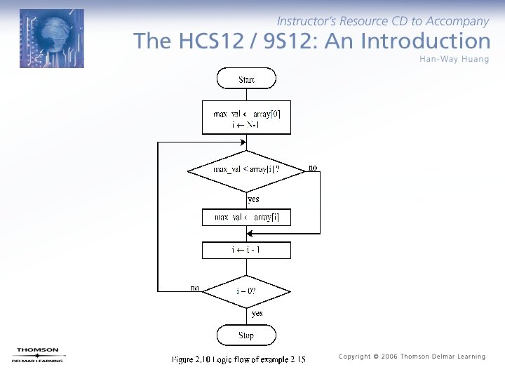

N equ org max_val ds. b org ldaa staa ldx ldab loop ldaa cmpa bge ldaa staa chk_end dex dbne forever bra array db db end 20 $1000 1 $1500 array max_val #array+N-1 #N-1 max_val 0, x chk_end 0, x max_val ; set array[0] as the temporary max ; “ ; start from the end of the array ; set loop count to N - 1 b, loop ; finish all the comparison yet? forever 1, 3, 5, 6, 19, 41, 53, 28, 13, 42, 76, 14 20, 54, 64, 74, 29, 33, 41, 45
![Bit Condition Branch Instructions [<label>] brclr (opr), (msk), (rel) [<comment>] [<label>] brset (opr), (msk),](http://slidetodoc.com/presentation_image_h2/0f26790fb6564364f1d8f89b13986e48/image-39.jpg "Bit Condition Branch Instructions [<label>] brclr (opr), (msk), (rel) [<comment>] [<label>] brset (opr), (msk),")
Bit Condition Branch Instructions [<label>] brclr (opr), (msk), (rel) [<comment>] [<label>] brset (opr), (msk), (rel) [<comment>] where opr specifies the memory location to be checked and must be specified using either the direct, extended, or index addressing mode. msk is an 8 -bit mask that specifies the bits of the memory location to be checked. The bits of the memory byte to be checked correspond to those bit positions that are 1 s in the mask. rel is the branch offset and is specified in the 8 -bit relative mode. For example, in the sequence loop inc count … brclr $66, $e 0, loop … the branch will be taken if the most significant three bits at $66 are all ones.

Example 2. 17 Write a program to compute the number of elements that are divisible by 4 in an array of N 8 -bit elements. Use the repeat S until C looping construct. Solution: A number divisible by 4 would have the least significant two bits equal 0 s. N equ org total ds. b org clr ldx ldab loop brclr bra yes inc chkend inx dbne forever bra array db end 20 $1000 1 $1500 total ; initialize total to 0 #array #N ; use B as the loop count 0, x, $03, yes ; check bits 1 and 0 chkend total b, loop forever 2, 3, 4, 8, 12, 13, 19, 24, 33, 32, 20, 18, 53, 52, 80, 82, 90, 94, 100, 102
![Instructions for Variable Initialization • [<label>] CLR opr [<comment>] where opr is specified using](http://slidetodoc.com/presentation_image_h2/0f26790fb6564364f1d8f89b13986e48/image-41.jpg "Instructions for Variable Initialization • [<label>] CLR opr [<comment>] where opr is specified using")
Instructions for Variable Initialization • [<label>] CLR opr [<comment>] where opr is specified using the extended or index addressing modes. The specified memory location is cleared. • [<label>] CLRA [<comment>] Accumulator A is cleared to 0 • [<label>] CLRB [<comment>] Accumulator B is cleared to 0

Shift and Rotate Instructions The HCS 12 has shift and rotate instructions that apply to a memory location, accumulators A, B, and D. A memory operand must be specified using the extended or index addressing modes. There are three 8 -bit arithmetic shift left instructions: [<label>] asl opr [<comment>] [<label>] asla [<comment>] [<label>] aslb [<comment>] -- memory location opr is shifted left one place -- accumulator A is shifted left one place -- accumulator B is shifted left one place The operation is C b 7 --------- b 0 0
![The HCS 12 has one 16 -bit arithmetic shift left instruction: [<label>] asld [<comment>]](http://slidetodoc.com/presentation_image_h2/0f26790fb6564364f1d8f89b13986e48/image-43.jpg "The HCS 12 has one 16 -bit arithmetic shift left instruction: [<label>] asld [<comment>]")
The HCS 12 has one 16 -bit arithmetic shift left instruction: [<label>] asld [<comment>] The operation is C b 7 --------- b 0 accumulator A b 7 --------- b 0 accumulator B 0 The HCS 12 has arithmetic shift right instructions that apply to a memory location and accumulators A and B. [<label>] asr opr [<comment>] [<label>] asra [<comment>] [<label>] asrb [<comment>] -- memory location opr is shifted right one place -- accumulator A is shifted right one place -- accumulator B is shifted right one place The operation is b 7 --------- b 0 C

The HCS 12 has logical shift left instructions that apply to a memory location and accumulators A and B. [<label>] lsl opr [<label>] lsla [<label>] lslb [<comment>] -- memory location opr is shifted left one place -- accumulator A is shifted left one place -- accumulator B is shifted left one place The operation is C b 7 --------- b 0 0 The HCS 12 has one 16 -bit logical shift left instruction: [<label>] lsld [<comment>] The operation is C b 7 ----------------- b 0 accumulator A accumulator B 0

The HCS 12 has three logical shift right instructions that apply to 8 -bit operands. [<label>] lsr opr [<label>] lsra [<label>] lsrb The operation is [<comment>] 0 -- memory location opr is shifted right one place -- accumulator A is shifted right one place -- accumulator B is shifted right one place b 7 --------- b 0 C The HCS 12 has one 16 -bit logical shift right instruction: [<label>] lsrd [<comment>] The operation is 0 b 7 ----------------- b 0 accumulator A accumulator B C

The HCS 12 has three rotate left instructions that operate on 9 -bit operands. [<label>] rol opr place [<label>] rola [<label>] rolb [<comment>] -- memory location opr is rotated left one [<comment>] -- accumulator A is rotated left one place -- accumulator B is rotated left one place The operation is b 7 --------- b 0 C The HCS 12 has three rotate right instructions that operate on 9 -bit operands. [<label>] ror opr [<comment>] place [<label>] rora [<comment>] [<label>] rorb [<comment>] -- memory location opr is rotated right one -- accumulator A is rotated right one place -- accumulator B is rotated right one place The operation is C b 7 --------- b 0
![Example 2. 18 Suppose that [A] = $95 and C = 1. Compute the](http://slidetodoc.com/presentation_image_h2/0f26790fb6564364f1d8f89b13986e48/image-47.jpg "Example 2. 18 Suppose that [A] = $95 and C = 1. Compute the")
Example 2. 18 Suppose that [A] = $95 and C = 1. Compute the new values of A and C after the execution of the instruction asla. Solution: Example 2. 19 Suppose that m[$800] = $ED and C = 0. Compute the new values of m[$800] and the C flag after the execution of the instruction asr $1000. Solution:
![Example 2. 20 Suppose that m[$1000] = $E 7 and C = 1. Compute](http://slidetodoc.com/presentation_image_h2/0f26790fb6564364f1d8f89b13986e48/image-48.jpg "Example 2. 20 Suppose that m[$1000] = $E 7 and C = 1. Compute")
Example 2. 20 Suppose that m[$1000] = $E 7 and C = 1. Compute the new contents of m[$1000] and the C flag after the execution of the instruction lsr $1000. Solution: Example 2. 21 Suppose that [B] = $BD and C = 1. Compute the new values of B and the C flag after the execution of the instruction rolb. Solution:
![Example 2. 22 Suppose that [A] = $BE and C = 1. Compute the](http://slidetodoc.com/presentation_image_h2/0f26790fb6564364f1d8f89b13986e48/image-49.jpg "Example 2. 22 Suppose that [A] = $BE and C = 1. Compute the")
Example 2. 22 Suppose that [A] = $BE and C = 1. Compute the new values of mem[$00] after the execution of the instruction rora. Solution:

Example 2. 23 Write a program to count the number of 0 s in the 16 -bit number stored at $1000 -$1001 and save the result in $1005. Solution: * The 16 -bit number is shifted to the right 16 time. * If the bit shifted out is a 0 then increment the 0 s count by 1. org db org zero_cnt rmb lp_cnt rmb org clr ldaa staa ldd loop lsrd bcs inc chkend dec bne forever bra end $1000 $23, $55 $1005 1 1 $1500 zero_cnt #16 lp_cnt $1000 chkend zero_cnt lp_cnt loop forever ; test data ; initialize the 0 s count to 0 ; place the number in D ; shift the lsb of D to the C flag ; is the C flag a 0? ; increment 1 s count if the lsb is a 1 ; check to see if D is already 0
 • For shifting right – The bit")
Shift a Multi-byte Number (1 of 3) • For shifting right – The bit 7 of each byte will receive the bit 0 of its immediate left byte with the exception of the most significant byte which will receive a 0. – Each byte will be shifted to the right by 1 bit. The bit 0 of the least significant byte will be lost. • Suppose there is a k-byte number that is stored at loc to loc+k-1. – Method for shifting right • Step 1: Shift the byte at loc to the right one place. • Step 2: Rotate the byte at loc+1 to the right one place. • Step 3: Repeat Step 2 for the remaining bytes.
 • For shifting left – The bit")
Shift a Multi-byte Number (2 of 3) • For shifting left – The bit 0 of each byte will receive the bit 7 of its immediate right byte with the exception of the least significant byte which will receive a 0. – Each byte will be shifted to the left by 1 bit. The bit 7 of the most significant byte will be lost. • Suppose there is a k-byte number that is stored at loc to loc+k-1. – Method for shifting left • Step 1: Shift the byte at loc+k-1 to the left one place. • Step 2: Rotate the byte at loc+K-2 to the left one place. • Step 3: Repeat Step 2 for the remaining bytes.
 Example 2. 24 Write a program to")
Shift a Multi-byte Number (3 of 3) Example 2. 24 Write a program to shift the 32 -bit number stored at $820 -$823 to the right four places. Solution: again ldab #4 ; set up the loop count ldx #$820 ; use X as the pointer to the left most byte lsr 0, X ror 1, X ror 2, X ror 3, X dbne b, again end

Boolean Logic Instructions • Changing a few bits are often done in I/O applications. • Boolean logic operation can be used to change a few I/O port pins easily.
 • The HCS 12 uses the E clock")
Program Execution Time (1 of 2) • The HCS 12 uses the E clock as a timing reference. • The frequency of the E clock is half of that of the crystal oscillator. • There are many applications that require the generation of time delays. • The creation of a time delay involves two steps: – Select a sequence of instructions that takes a certain amount of time to execute. – Repeat the selected instruction sequence for an appropriate number of times. • For example, the instruction sequence on the next page takes 40 E cycles to execute. By repeating this instruction sequence a certain number of times, any time delay can be created. – Assume that the HCS 12 runs under a crystal oscillator with a frequency of 16 MHz, then the E frequency is 8 MHz and, hence, its clock period is 125 ns. – Therefore, the instruction sequence on the next page will take 5 ms to execute.
 loop psha pula psha pula nop dbne x,")
Program Execution Time (2 of 2) loop psha pula psha pula nop dbne x, loop ; 2 E cycles ; 3 E cycles ; 1 E cycle ; 3 E cycles

Example 2. 25 Write a program loop to create a delay of 100 ms. Solution: A delay of 100 ms can be created by repeating the previous loop 20, 000 times. The following instruction sequence creates a delay of 100 ms. ldx #20000 loop psha ; 2 E cycles pula ; 3 E cycles psha pula psha pula nop ; 1 E cycle dbne x, loop ; 3 E cycles

Example 2. 26 Write an instruction sequence to create a delay of 10 seconds. Solution: By repeating the previous instruction sequence 100 times, we can create a delay of 10 seconds. ldab out_loop ldx in_loop psha pula psha pula nop dbne #100 #20000 ; 2 E cycles ; 3 E cycles ; 1 E cycle x, in_loop ; 3 E cycles b, out_loop ; 3 E cycles
- Slides: 58