Assembly language programming Learning assembly language programming will

Assembly language programming • Learning assembly language programming will help understanding the operations of the microprocessor • To learn: – Need to know the functions of various registers – Need to know how external memory is organized and how it is addressed to obtain instructions and data (different addressing modes) – Need to know what operations (or the instruction set) are supported by the CPU. For example, powerful CPUs support floating-point operations but simple CPUs only support integer operations

How to learn programming • • C –Concept L – Logic thinking P – Practice Concept – we must learn the basic syntax, such as how a program statement is written • Logic thinking – programming is problem solving so we must think logically in order to derive a solution • Practice – write programs

Assembly Program • The native language is machine language (using 0, 1 to represent the operation) • A single machine instruction can take up one or more bytes of code • Assembly language is used to write the program using alphanumeric symbols (or mnemonic), eg ADD, MOV, PUSH etc. • The program will then be assembled (similar to compiled) and linked into an executable program. • The executable program could be. com, . exe, or. bin files

Flow of program development Program. asm Assemble Object file. obj link Executable file. exe

Example • Machine code for mov AL, 00 H • B 4 00 (2 bytes) • After assemble, the value B 400 will be stored in the memory • When the program is executed, then the value B 400 is read from memory, decoded and carry out the task

Assembly Program • Each instruction is represented by one assembly language statement • The statement must specify which operation (opcode) is to be performed and the operands • Eg ADD AX, BX • ADD is the operation • AX is called the destination operand • BX is called the source operand • The result is AX = AX + BX • When writing assembly language program, you need to think in the instruction level
*100 • In assembly language,")
Example • In c++, you can do A = (B+C)*100 • In assembly language, only one instruction per statement A=B A = A+C A = A*100 ; only one instruction - MOVE ; only one instruction - ADD ; only one instruction - Multiply

Format of Assembly language • General format for an assembly language statement • Label Instruction Comment • Start: Mov AX, BX ; copy BX into AX Start is a user defined name and you only put in a label in your statement when necessary!!!! The symbol : is used to indicate that it is a label

8086 Software Model

Software model • In 8086, memory is divided into segments • Only 4 64 K-byte segments are active and these are: code, stack, data, and extra • When you write your assembly language program for an 8086, theoretically you should define the different segments!!! • To access the active segments, it is via the segment register: CS (code), SS (stack), DS (data), ES (extra) • So when writing assembly language program, you must make use of the proper segment register or index register when you want to access the memory

Registers • In assembly programming, you cannot operate on two memory locations in the same instruction • So you usually need to store (move) value of one location into a register and then perform your operation • After the operation, you then put the result back to the memory location • Therefore, one form of operation that you will use very frequent is the store (move) operation!!! • And using registers!!!!!

Example • In C++ A = B+C ; A, B, C are variables • In assembly language A, B, C representing memory locations so you cannot do A = B+C – MOV AL, B ; move value of B into AL register – ADD, AL, C ; do the add AL = AL +C – MOV A, AL ; put the result to A

Data registers • AX, BX, CX, and DX – these are the general purpose registers but each of the registers also has special function Example – AX is called the accumulator – to store result in arithmetic operations • Registers are 16 -bit but can be used as 2 8 -bit storage • Each of the 4 data registers can be used as the source or destination of an operand during an arithmetic, logic, shift, or rotate operation. • In some operations, the use of the accumulator is assumed, eg in I/O mapped input and output operations

Data register • In based addressing mode, base register BX is used as a pointer to an operand in the current data segment. • CX is used as a counter in some instructions, eg. CL contains the count of the number of bits by which the contents of the operand must be rotated or shifted by multiple-bit rotate • DX, data register, is used in all multiplication and division, it also contains an input/output port address for some types of input/output operations

Pointer and index registers • Stack – is used as a temporary storage • Data can be stored by the PUSH instruction and extracted by the POP instruction • Stack is accessed via the SP (Stack Pointer) and BP (Base Pointer) • The BP contains an offset address in the current stack segment. This offset address is employed when using the based addressing mode and is commonly used by instructions in a subroutine that reference parameters that were passed by using the stack
 and Destination index register (DI)")
Pointer and Index Register • Source index register (SI) and Destination index register (DI) are used to hold offset addresses for use in indexed addressing of operands in memory • When indexed type of addressing is used, then SI refers to the current data segment and DI refers to the current extra segment • The index registers can also be used as source or destination registers in arithmetic and logical operations. But must be used in 16 -bit mode

Data types • Data can be in three forms: 8 -bit, 16 -bit, or 32 -bit (double word) • Integer could be signed or unsigned and in bytewide or word-wide • For signed integer (2’s complement format), the MSB is used as the sign-bit (0 for positive, 1 for negative) • Signed 8 -bit integer 127 to – 128, • For signed word 32767 to – 32768 • Latest microprocessors can also support 64 -bit or even 128 -bit data • In 8086, only integer operations are supported!!!

A sample program. code ; indicate start of code segment. startup ; indicate start of program mov AX, 0 mov BX, 0000 H mov CX, 0 mov SI, AX mov DI, AX mov BP, AX END ; end of file The flow of the program is usually top-down and instructions are executed one by one!!!

Assembly programming In general, an assembly program must include the code segment!! Other segments, such as stack segment, data segment are not compulsory There are key words to indicate the beginning of a segment as well as the end of a segment. Just like using main(){} in C++ Programming Example DSEG segment ‘data’ ; define the start of a data segment DSEG ENDS ; defines the end of a data segment Segment is the keyword DSEG is the name of the segment Similarly key words are used to define the beginning of a program, as well as the end.

Assembly language programming Example CSEG segment ‘code’ START PROC FAR RET START ENDP CSEG ends End start ; define the start of a program (procedure) ; return ; define the end of a procedure ; end of everything Different assembler may have different syntax for the definition of the key words !!!!! Start is just a name it could be my_prog, ABC etc

More sample Stacksg segment para ‘stack’ …. ; define the stack segment Stacksg ends Datasg segment para …… ; declare data inside the data segment Datasg ends Codesg segment para ‘code’ Main proc far ; assume ss: stacksg, ds: datasg, cs: codesg mov ax, datasg mov ds, ax …. mov ax, 4 c 00 H int 21 H Main endp Codesg ends End of everything end main

Definitions To declare a segment, the syntax is: segment_name SEGMENT alignment class Example Stacksg segment PARA (this statement is used in previous slide) PARA – define the alignment of the segment base address, the segment with a starting addressing that is evenly Divisible by 16 (ie the last digit is 0). But the default value is also base address divisible by 16 so the key word PARA can be ignored!

Definition • ‘data’, ‘code’ – class entry. Is used to group related segments when linking. The linker automatically groups segments of the same class in memory • PROC – define procedures (similar to a function) inside the code segment. Each procedure must be identified by an unique name. At the end of the procedure, you must include the ENDP

Definitions FAR – is related to program execution. When you request execution of a program, the program loader uses this procedure as the entry point for the first instruction to execute. Assume – to associate, or to assign, the name of a segment with a segment register (ie let CS point to the code segment, DS points to data segment etc) In some assembler, you need to move the base address of a segment directly into the segment register!!! END – ends the entire program and appears as the last statement. Usually the name of the first or only PROC designated as FAR is put after END

Syntax of a simple assembly language program • If you are doing something simple then you do not need to define the segment • Everything will be stored in the code segment

start: mov DL, 0 H mov CL, op 1 mov AL, data step: cmp AL, op 1 jc label 1 sub AL, op 1 inc DL jmp step label 1: mov AH, DL ; move 0 H to DL ; move op 1 to CL ; move data to AL ; compare AL and op 1 ; if carry =1 jump to label 1 ; AL = AL –op 1 ; DL = DL+1 ; jump to step ; move DL to AH HLT ; Halt end of program data db 45 ; define a variable called data op 1 db 6 ; define a variable called op 1

Assembler for 8086 WASM – a freeware can be download from internet (http: //user. mc. net/~warp/software_wasm. html) Emu 8086 (http: // www. emu 8086. com) – there is a trial version but it does not support all the features such as interrupt The emu 8086 consists of a tutorial and the reference for a complete instruction set Keil – www. keil. com

Defining data in a program Data is usually stored in the data segment You can define constants, work areas (a chunk of memory ) Data can be defined in different length (8 -bit, 16 -bit) 8 -bit then use DB 16 -bit then use DW The definition for data: [name] Dn expression ; Dn is either DB or DW Name – a program that references a data item by means of a name. The name of an item is otherwise optional Dn – this is called the directives. It defines length of the data Expression – define the values (content) for the data

Examples for data FLDA DB ? ; define an uninitialized item called FLDA 8 -bit FLDB DB 25 ; initialize a data to 25 Define multiple data under the same name (like an array) FLDC DB 21, 22, 23, 34 ; the data are stored in adjacent bytes FLDC stores the first value FLDC + 1 stores the second value You can do mov AL, FLDC+3

Example for data definition DUP – duplicate DUP can be used to define multiple storages DB 10 DUP (? ) ; defines 10 bytes not initialize DB 5 DUP (12) ; 5 data all initialized to 12 String : DB ‘this is a test’ EQU – this directive does not define a data item; instead, it defines a value that the assembler can use to substitute in other instructions (similar to defining a constant in C programming or using the #define ) factor EQU 12 mov CX, factor

Assembly Program • Assembly language should be more effective and it will take up less memory space and run faster • In real-time application, the use of assembly program is required because program that is written in a high-level language probably could not respond quickly enough • You can also put assembly codes into your C++ program in order to reduce the execution time!!!!

Assembly language programming • The syntax for different microprocessor may be different but the concept is the same so once you learn the assembly programming for one microprocessor, you can easily program other kinds of system • For example, programming the 8051 series is very similar to the 8086

Addressing Modes • Function of the addressing modes is to access the operands • Available modes (9 modes): register addressing, immediate addressing, direct addressing, register indirect addressing, based addressing, indexed addressing, based indexed addressing, string addressing, and port addressing • Addressing modes provide different ways of computing the address of an operand so that you can utilize your data with different techniques

Why addressing mode is important? • In c++, you can define an array, or a variable – – – int x[10], y, *z; Then to access different elements, you can do Z=x; *(x+2); x[0] = y How this can be done using assembly language programming? This is via different addressing modes!!!!

Register addressing mode • The operand to be accessed is specified as residing in an internal register of the 8086 • Eg MOV AX, BX • Move (MOV) contents of BX (the source operand), to AX (the destination operand) • Both operands are in the internal registers
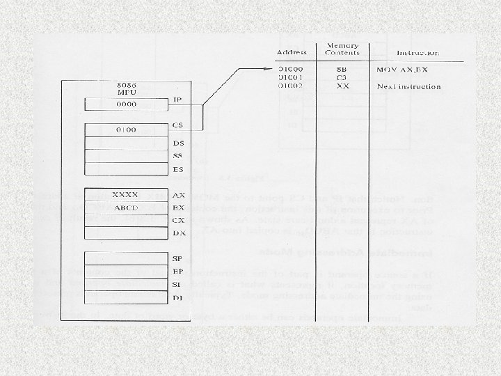

Pay attention to the value of IP and content of AX, BX

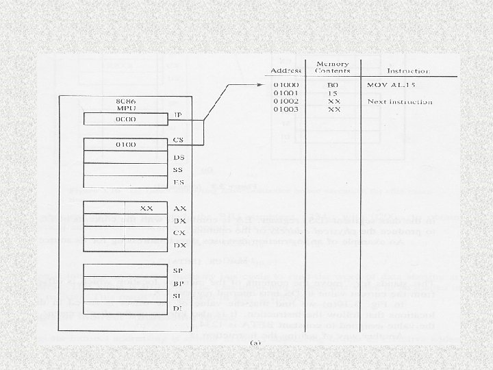
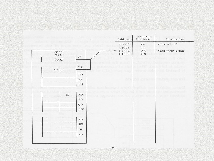
Immediate addressing mode Source operand is part of the instruction Usually immediate operands represent constant data The operands can be either a byte or word e. g MOV AL, 15 15 is a byte wide immediate source operand Or it could be MOV AL, #15 The immediate operand is stored in program storage memory (i. e the code segment) This value is also fetched into the instruction queue in the BIU No external memory bus cycle is initiated!

Direct addressing mode • Move a byte or word between a memory location and a register • the locations following the instruction opcode hold an effective memory address (EA) instead of data • The address is a 16 -bit offset of the storage location of the operand from the current value in the data segment register • Physcial address = DS + offset • The instruction set does not support a memory-tomemory transfer!

Direct addressing • Data is assumed to be stored in the data segment so DS is used in calculating the physical address!!! • External memory bus cycle is needed to do the read • Example of direct addressing: mov AL, var 1 • Where Var 1 can be regarded as a variable

Register indirect addressing mode • Transfer a byte or word between a register and a memory location addressed by an index or base register – Example MOV AL, [SI] – SI – index register – The symbol [] always refer to an indirect addressing • The effective address (EA) is stored either in a pointer register or an index register • The pointer register can be either base register BX or base pointer register BP • The index register can be source index register SI, or destination index register DI • The default segment is either DS or ES
![Register indirect addressing • Eg MOV AX, [SI] • Value stored in the SI](http://slidetodoc.com/presentation_image_h2/63ff4791b651257ce4e6b6a981444387/image-44.jpg "Register indirect addressing • Eg MOV AX, [SI] • Value stored in the SI")
Register indirect addressing • Eg MOV AX, [SI] • Value stored in the SI register is used as the offset address • The segment register is DS in this example • Meaning of the above is to move the data stored in the memory location : DS + SI to the AX register • In register indirect addressing mode, the EA (effective address) is a variable and depends on the index, or base register value
 Content 01236 19 01235 18 01234 20 01233 According to the")
Address (in HEX) Content 01236 19 01235 18 01234 20 01233 According to the memory map The result of the operation Mov [BX], CL will result in what? ? ? If CL = 88 and BX = 1233 H and DS =0 H Physical address = DS + BX = 01233 H

Different Addressing modes MOV AL, BL MOV AL, 15 H MOV AL, abc MOV AL, [1234 H] MOV AL, [SI] MOV AL, [BX+4] MOV AL, ARRAY[3] MOV AL, [BX+DI+4] MOV AL, ARRAY[BX+DI] Register addressing mode immediate Direct abc is a variable 1234 H is the offset address Register indirect Base plus index Register relative Base relative plus index

How to move the address of a variable to a register ? • When using indirect addressing, such as – MOV AL, [SI] – SI is an address so how can we initialize SI? • This is by the instruction called LEA (Load Effective Address) • LEA is similar to x = &y in C++ • Syntax of LEA: – LEA SI, ARRAY

Base-plus-index addressing mode • Move a byte or word between a register and the memory location addressed by a base register (BP or BX) plus an index register (DI or SI) • Physical address of the operand is obtained by adding a direct or indirect displacement to the contents of either base register BX or base pointer register BP and the current value in DS and SS, respectively. • Eg MOV [BX+SI], AL • Move value in AL to a location (DS+BX+SI) • If BP is used then use SS instead of DS
 often holds the beginning")
Application of Base + index • The base register (BX) often holds the beginning location of a memory array, while the index register (SI) holds the relative position of an element in the array • Change the value of SI then you can access different elements in the array

Register relative addressing mode • Move a byte or word between a register and memory location addressed by an index or base register plus a displacement • Eg MOV AL, ARRAY[SI] • EA = value of SI + ARRAY • Physical address = EA + DS • Eg mov AX, [BX+4] • Eg mov AX, array[DI+3] • This is similar to the base-plus-index

Base relative plus index addressing mode • Transfers a byte or word between a register and the memory location addressed by a base and an index register plus a displacement • Combining the based addressing mode and the indexed addressing mode together • Eg MOV AH, [BX+DI+4] • EA = value of BX + 4 + value of DI • Physical address = DS + EA • This can be used to access data stored as a 2 -D matrix • Eg mov AX, array[BX+DI]

Example • Select an instruction for each of the following tasks: – Copy BL into CL • Mov CL, BL – Copy DS into AX • Mov AX, DS Suppose that DS=1100 H, BX=0200 H, LIST=0250 H, and SI=0500 H, determine the address accessed by each of the following instructions: mov LIST[SI], DX (offset address: LIST + SI=0750 H, PA = offset +DS = 11750 H) mov CL, LIST[BX+SI] ( offset address: LIST+BX+SI = 0950 H, PA = 11950 H) mov CH, [BX+SI] (offset address: BX+SI = 0700 H, PA = 11700 H)

String addressing mode • The string instructions of the 8086 instruction set automatically use the source (SI) and destination index registers (DI) to specify the effective addresses of the source and destination operands, respectively. • Instruction is MOVS • There is no operand after movs • Don’t need to specify the register but SI and DI are being used during the program execution

Port addressing mode • Port addressing is used in conjunction with IN and OUT instruction to access input and output ports. • Any of the memory addressing modes can be used for the port address for memory-mapped ports. • For ports in the I/O address space, only the direct addressing mode and an indirect addressing mode using DX are available • Eg IN AL, 15 H ; second operand is the port number • Input data from the input port at address 1516 of the I/O address space to register AL • Eg IN AL, DX • Load AL with port number stored in DX

Exercises 1. Compute the physical address for the specified operand in each of the following instructions: MOV [DI], AX (destination operand) [DI] refers to the address 0200 so PA = 0 B 200 H MOV DI, [SI] (source operand) [SI] refers to 0100 so PA = 0 B 100 H) MOV XYZ[DI], AH (destination operand) XYZ[DI] refers to 0400+0200, PA = 0 B 600 H Given CS=0 A 00, DS=0 B 00, SI=0100, DI=0200, BX=0300, XYZ=0400

Exercises 2. Express the decimal numbers that follows as unpacked and packed BCD bytes (BCD – binary coded decimal) a. 29 b. 88 Ans. unpacked BCD takes 1 byte per-digit so 29 becomes 0000001001 as packed 00101001 3. How would the BCD numbers be stored in memory starting at address 0 B 000 Ans. if it is packed BCD then 29 will occupy one byte at 0 B 000, if as unpacked BCD then it occupies 2 bytes 00000010 at 0 B 001 and 00001001 at 0 B 000)

Instruction set • A total of 117 basic instructions • 5 groups: data transfer, arithmetic, logic, shift, and rotate • Data transfer instructions – to move data either between its internal registers or between an internal register and a storage location in memory • Cannot move data from one memory location to another memory location • When the segment register is used as an operand then the move instruction must apply to a 16 -bit data • Mov SS, data ; then data must be 16 -bit
 to")
Move instruction Mnemonic Meaning Format Operation Flags affected Move mov D, S (S) to (D) none Destination (D) Source (S) Memory AX AX Memory Register Memory Register Immediate Memory Immediate Seg-reg Reg 16 Seg-reg Mem 16 Seg-reg

Special data transfer instructions • XCHG – exchange data between the source and destination • Eg XCHG AX, DX • Then value in DX is stored in AX and value in AX stored in DX

• • • Special data transfer instruction LEA – load effective address LEA is are very important operation because it allows you to obtain an address of a variable or an array then you can apply the relative addressing modes!!!! Eg LEA SI, INPUT To load a specified register with a 16 -bit offset address Similar to x = &y in a C++ program

Example of LEA Dat db 11 H, 22 H, 33 H, 44 H LEA BX, dat Mov AL, [BX+2] ; this is register relative addressing mode What is being stored in AL ? ? ?
![• LDS – load register and DS • Eg LDS SI, [200] •](http://slidetodoc.com/presentation_image_h2/63ff4791b651257ce4e6b6a981444387/image-62.jpg "• LDS – load register and DS • Eg LDS SI, [200] •")
• LDS – load register and DS • Eg LDS SI, [200] • LDS will load a specified register (SI) and the DS • 4 bytes of data will be fetched the first two stored in SI and the following two stored in DS • LES – load register and ES • LES will load a specified register and the ES

Arithmetic instructions • Some examples of available arithmetic operations: add, substract, multiply, etc. • Can apply to unsigned, binary bytes, words, unpacked, packed decimal bytes, or ASCII numbers • Packed decimal – two BCD digits are packed into a byte register or memory location • Unpacked decimal numbers are stored one BCD digit per byte • After an arithmetic operation, the flags are updated accordingly

Arithmetic instructions ADD Add byte or word ADC Add byte or word with carry Increment byte or word by 1 AAA ASCII adjust for addition DAA Decimal adjust for addition Subtract byte or word Sbb Subtract byte or word with borrow DEC Decrement byte or word by 1 NEG Negate byte or word AAS ASCII adjust for subtraction DAS Decimal adjust for subtraction MUL Multiply byte or word unsigned IMUL Integer multiply byte or word AAM ASCII adjust for multiply Divide byte or word unsigned Idiv Integer divide byte or word AAD ASCII adjust for division CBW Convert byte to word CWD Convert word to doubleword

Addition related operations Mnemonic Meaning Format Addition Add D, S D = S+D CF = carry ADC Add with carry ADC D, S D = S+D+CF OF, SF, ZF, AF, PF, CF CF = carry INC Increment by 1 INC D D = D+1 AAA ASCII adjust for addition AAA AF, CF, OF, SF, ZF, PF undefined DAA Decimal adjust for DAA addition SF, ZF, AF, PF, CF, OF undefined Destination Source Register Memory Register Immediate Memory Immediate AX Immediate Operation Flags affected OF, SF, ZF, AF, PF, CF OF, SF, ZF, AF, PF

Subtraction Mnemonic Meaning Format Operation Flags affected Subtract Sub D, S D = D-S CF = borrow OF, SF, ZF, AF, PF, CF Sbb Subtract with borrow SBB D, S D = D-S-CF OF, SF, ZF, AF, PF, CF Decrement by 1 DEC D D=D-1 OF, SF, ZF, AF, PF Negate Neg D D=0 -D CF =1 OF, SF, ZF, AF, PF, CF DAS Decimal adjust for subtraction DAS OF, SF, ZF, AF, PF, CF undefined AAS ASCII adjust for subtraction AAS OF, SF, ZF, AF, PF, CF undefined

Subtraction operands Destination Source Register Memory Register AX Immediate Register Immediate Memory immediate

Example If BX = 3 A NEG BX Give FFC 6 NEG – make the operand negative (2’s complement) Executing the NEG instruction causes the following 2’s complement subtraction 00 - (BX) = 0000 + 2’s complement of 3 A = 0000 + FFC 6 = FFC 6

Multiplication • When multiplying 8 -bit data, result is 16 -bit and stored in AX • When multiplying 16 -bit data, result is 32 -bit and result stored in AX and DX • The AX holds the LSB and DX MSB • Only the source operand is specified and the other operand is in AL, or AX. This is also the same in division • In division, AH is the remainder and AL is the quotient • For 16 -bit, AX contains the quotient and DX contains the remainder
 MUL")
Multiplication and division functions Mnemonic Meaning Format Operation Flags affected MUL Multiply (Unsigned) MUL S AX = AL*S 8 DX, AX = AX*S 16 OF, CF, SF, ZF, AF, PF undefined DIV Division (unsigned) DIV S AL = Q (AX/S 8) AH = R(AX/S 8) OF, CF, SF, ZF, AF, PF undefined IMUL Integer multiply (signed) IMUL S AX = AL*S 8 DX, AX=AX*S 16 OF, CF, SF, ZF, AF, PF undefined IDIV Integer divide (signed) IDIV S AX = Q(AX/S 8) AH=R(AX/S 8) AX = Q(DX, AX)/S 16 DX=R(DX, AX)/S 16 If Q is positive and exceeds 7 FFF or if Q is negative and becomes less than 8001 then type 0 interrupt occurs OF, CF, SF, ZF, AF, PF undefined

Multiplication related functions Mnemonic Meaning Format Operation Flags affected AAM Adjust AL for multiplication Ascii adjust after Multiplication for BCD values AAM AH=Q(AL/10) AL=R(AL/10) SF, ZF, PF, OF, AF, CF undefined AAD Adjust AX for division Prepare 2 BCD values for division AAD AL=(AH*10+AL) SF, ZF, PF, OF, AF, CF AH =00 undefined CBW Convert byte to word CBW All bits of AH = (MSB of AL) None CWD Convert word to double word CWD All bits of DX = MSB of AX none

Example If AL is – 1 and CL is – 2, what will be the result produced In AX for MUL CL IMUL CL is unsigned multiply = FD 02 IMUL CL is signed multiply = 2
 to word (16 -bit) •")
Special functions • CBW – convert byte (8 -bit) to word (16 -bit) • CBW – fill AH with 0 if AL is positive; fill AH with 1 s if AL is negative then AH becomes FF • CWD – convert word (16 -bit) to double word (32 bit) and the DX register is used to store the high order word • CWD – fill DX with 0 if AL is positive; fill DX with 1 s if AX is negative then DX becomes FF • Use CBW when doing 8 -bit operation • Use CWD when doing 16 -bit operation

Example What is the result of executing the following sequence Of instructions? MOV AL, A 1 CBW CWD Ans. AX = FFA 1 after CBW DX = FFFF after CWD

A simple application • Try to write a simple assembly program to convert from Centigrade (Celsius) to Fahrenheit • The equation for the conversion is • f = c * 9 / 5 + 32 • What operations are required? • Do you need to define variables?
 and NOT • Eg")
Logic Instructions • Logic operations include: AND, OR, exclusive-OR (XOR) and NOT • Eg AND AX, BX • Result is stored in AX • Operation is applied to bits of the operands

Exercise • Describe the result of executing the following: • • • MOV AND OR XOR NOT AL, 0101 B AL, 00011111 B AL, 11000000 B AL, 00001111 B AL Ans. AL = 00100101 NOTE: NOT not equal to NEG (AL = 00010101 B) (AL = 11011010 B) (AL = 00100101 B)

Application of logical operations • If you only want to examine a particular bit in a 8 -bit pattern you can do – AND AL, #00010000 The above tries to examine bit 4 of AL After AND check the ZERO flag Z=1 then bit 4 =0 else bit 4=1 • If you want to clear a register to 0 – XOR BL, BL

Exercise • Write a program to count the number of even numbers included in an array by using: – Logical operation(s)

Shift Instructions • • • There are 4 shift operations Can perform: logical shift and arithmetic shift Can shift left as well as right Logical shift – the vacated bit will be filled with ‘ 0’ Arithmetic shift – the vacated bit will be filled with the original most significant bit (this only applies in right shift, in left shift vacated bit is filled with ‘ 0’ as well. ) • Arithmetic shift will maintain the ‘sign’ of the original data • If shift more than 1 bit then the number of bits to be shifted is stored in CL

Shift left carry If content is 10010011 then after shift Carry = 1 result is 00100110 Shift right carry If content is 10010011 then after shift Carry = 1 result is 01001001 If arithmetic shift then result is 11001001

Shift operations Mnemonic Meaning Format Operation Flags affected SAL/SHL Shift arithmetic left/shift logical left SAL/SHL D, Count Shift the (D) left by the number of bit positions equal to count and fill the vacated bits positions on the right with zeros CF, PF, SF, ZF, OF, AF undefined OF undefined if count not equal to 1 SHR Shift logical right SHR D, Count Shift the (D) right by the number of bit positions equal to count and fill the vacated bits positions on the left with zeros CF, PF, SF, ZF, OF, AF undefined OF undefined if count not equal to 1 SAR Shift arithmetic right SAR D, Count Shift the (D) right by the number of bit positions equal to count and fill the vacated bits positions on the left with the original most significant bit CF, PF, SF, ZF, OF, AF undefined OF undefined

Rotate Instructions • Rotate is similar to shift • The vacate bit is filled with the bit rotated out from the other side • Rotate left through carry (RCL) – bit rotated out is stored in the carry flag, the vacated bit is filled by the carry flag

Rotate 1 1 0 0 Rotate right 0 1 1 0 0 0 After Rotate right thro’ carry 0 1 1 0 0 0 1 1 1 1 0 0 1 0 After

Example of rotate • Eg RCR BX, CL ; rotate right thro’ carry • If CL = 0416 and BX = 123416 what is the result of the above operation? – 1000 0001 0010 0011 if C is 0 at the beginning

Rotate Operations Mnemonic Meaning Format Operation Flags affected ROL Rotate left ROL D, Count Rotate the D left by the number of bit positions equal to Count. Each bit shifted out from the leftmost bit goes back into the rightmost bit position CF OF undefined if count 1 ROR Rotate right ROR D, Count Rotate the D right by the number of bit positions equal to Count. Each bit shifted out from the rightmost bit goes back into the leftmost bit position CF OF undefined if count 1

Rotate operation Mnemonic Meaning Format Operation Flags affected RCL Rotate left thro’ carry RCL D, Count Same as ROL CF except carry is OF undefined attached to D if count 1 for rotation RCR Rotate right thro’ carry RCR D, Count Same as ROL CF except carry is OF undefined attached to D if count 1 for rotation

Applications of shift/rotate • To examine bit 6 of the AL register – RCL AL, 2 • To implement a multiply – Shift a pattern to left = x 2 – 00000100 = 4 after shifting to left 00001000 = 8 – Shift to right = /2 – 00000100 after shifting to right 00000010 = 2 • 3 x 9 – Binary pattern of 9 = 1001 – 3 x 9 = 3 x 23 + 3 x 20 – 3 x 23 = shifting pattern of 3 to left 3 times + the original value (shift 0 time) – Binary pattern of 3 00000011 – 00011000 (after 3 shift) + 00000011 – Result = 00011011 = ? ? ?

Exercise If AL = 128, BL = -4 After the following: ADD AL, 3 ADC BL, AL RCL BL, 1 ; this is rotate left thro’ carry, this does not change the ; sign or overflow Q. What will be the carry, sign and overflow flag?

Exercise • Write a program to count the number of odd numbers included in an array by using: – Shift/rotate operation

Exercise AX = 0010 H BX = 0020 H CX = 0030 H SI = 0100 H DI = 0200 H CF = 1 H DS: 100 = 10 H DS: 101 = 00 H DS: 121 = FFH DS: 130 = 08 H DS: 150 = 02 H DS: 151 = 00 H DS: 201 = 00 H DS: 210 = 40 H DS: 220 = 30 H DS: 221 = 00 H DX = 0040 H DS: 120 = FFH DS: 131 = 00 H DS: 200 = 30 H DS: 211 = 00 H
 ADC SI, AX (SI")
ADD AX, 00 FF ( AX = 010 F H) ADC SI, AX (SI = 0111 H) INC BYTE PTR [0100]; Byte ptr indicate the size of memory data addressed by the memory pointer (the value refers to is 10 H so it becomes 11 H) SUB DL, BL (DL = 40 BL =20 so result = 20 H) SBB DL, [0200] (DL = 40 H, [0200] refers to 30 H so result is 09 H ) DEC BYTE PTR [DI+BX] (data refers to by byte ptr [DI+BX] is 30 H after DEC = 29 H ) NEG BYTE PTR [DI] + 0010 ( NEG 40 H = 1100 0000 ) MUL DX (10 x 40 so AX = 0400 H DX = 0000 H ) IMUL BYTE PTR [BX + SI] (AX = 0 FF 0 H , DX = 0000 H) DIV BYTE PTR[SI] + 0030 (value refers to by Byte PTR[SI]+0030 is 08 H (one byte) so after the division AH = 00 AL = 02) IDIV BYTE PTR [BX][SI]+0030 ( the value refers to is 02 H so after div AH =00 AL =08)

Exercise 1. How would the decimal number 1234 be coded in ASCII and stored in memory starting at address 0 C 000 H? Assume that least significant digit is stored at the lower addressed memory location 1 = (31 H in 0 C 003 H) 2 = (32 H in 0 C 002 H) 3 = (33 H in 0 C 001 H) 4 = (34 H in 0 C 000 H) 2. If register BX contains the value 010016, register DI contains 0010 and register DS contains 1075, what physical memory location is swapped when the following instruction is executed XCHG [BX+DI], AX PA = 10750+0100+0010 = 10860 H 3. Compute the physical address for the specified operand in each of the following instructions: MOV [DI], AX (destination operand) (0 B 000+0200 = 0 B 200) MOV DI, [SI] (source operand) (0 B 000+0100 = 0 B 100) MOV DI+XYZ, AH (destination operand) (0 B 000+0200+0400 = 0 B 600) Given CS=0 A 00, DS=0 B 00, SI=0100, DI=0200, BX=0300, XYZ=0400
- Slides: 93