Chapter 1 Introduction to Pneumatics Definitions Principle Definition

 The term pneumatics describes the")
 to power machine")


 Compressed atmospheric air which stores energy in")

 §")

 of")


 Type of flow 1. Laminar flow")
 Pressure loss / Pressure drop is a term used to")
 Law of Conservation of mass Matter cannot be created or")


 • Air is non-explosive, it is")


 § A air compressor converts the mechanical energy")

 Air taken in at atmospheric pressure is compressed")


 shafts. They work")


")


 Diaphragm type")


- Slides: 64
Chapter 1 Introduction to Pneumatics
Definitions & Principle Definition Greek pneuma = breath (bernafas) The term pneumatics describes the use of compressed air in drive and control engineering. The introduction of pneumatics into mechanisation and automation began in the middle of the 20 th century.
Definition & Principle PNEUMATICS §is application of compressed air (pressurized air) to power machine or control or regulate machines §may be defined as branch of engineering science which deals with the study of the behavior and application of compressed air §can also be defined as the branch of fluid power technology that deals with generation, transmission and control of power using pressurized air Gas in a pneumatic system behaves like a spring since it is compressible. For example, in tires and air-cushioned springs, compressed air acts as a cushion to absorb shock. Air brakes on locomotives and large trucks contribute greatly to the safety of railroad and truck transportation.
Pneumatic principle
APPLICATION AREAS Areas of use Nowadays, compressed air can be found in almost all field of engineering, e. g. : - Industry Rail transport Motor vehicles Shipping Construction - Trade Air transport Mining Medicine Defence
APPLICATION AREAS Application Area Generation of linear motion Example clamping, feeding, lifting and lowering, opening & closing, pneumatic press, transfer table, tool loading, industrial robot, etc Generation of rotary motion screw drivers, grinders, tread cutters, drill, etc sequence control, monitoring, locking, etc workshop air, paint spraying, etc Applications in control Others
Compressed Air Fundamental Compressed Air (pressurized air) Compressed atmospheric air which stores energy in its compressed state (usually greater than that of the atmosphere) and has the potential to perform work. Among the simplest ways that air can be taken from the atmosphere and compressed within a smaller volume is through the use of a hand pump. To see how a hand pump works, look no further than a simple bicycle pump, which takes air and pumps it into a bike tire when a person repeatedly pushes a hand or foot pedal. When the pedal is compressed, air enters the pump through an intake and is “pushed” into the bike tire via a plunger within the pump casing. Once the air has entered the tire, it officially has become compressed air, and the more air that enters the tire results in higher air pressure within the volume of the tire.
Compressed Air Fundamental Pressure measurement Instruments used to measure pressure are called pressure gauges or vacuum gauges. A manometer could also be referring to a pressure measuring instrument, usually limited to measuring pressures near to atmospheric. Standard model for pressure gauge: 1. Bourdon tube pressure gauge 2. Diaphragm pressure gauge 3. Piston spring pressure gauge
Compressed Air Fundamental Pressure are measure in unit of: § Pascal, Pa (N/m²) § bar § psi (lbf/sq. in. ) § Torr (mm Hg) Conversion table for different pressure unit 2 6. 9 x 10⁻²
Compressed Air Fundamental Gauge pressure Pressure measuring devices normally measure the difference between applied pressure and atmospheric pressure and thus indicate gauge pressure (or vacuum pressure in the case of a vacuum gauge). The equivalent absolute pressure is determined by relating the gauge pressure to zero pressure as a datum. In the case of positive pressure above atmosphere, absolute pressure is the sum of the gauge and the atmospheric pressure (normally assumed to be 1 bar). Since pneumatics are mainly concerned with gauge pressure less than 10 bar, the difference between absolute and gauge pressure can be significant.
Compressed Air Fundamental Perfect Gas principle Boyle's law states that the volume (V) of a gas, at constant temperature varies inversely with the pressure (P). = a constant Charles's law states that the volume of a gas, at constant pressure, varies directly with the absolute temperature (T). = a constant Amonton's law states that the pressure of a gas, at constant volume, varies directly with the absolute temperature. = t constant
Compressed Air Fundamental Relationship between pressure, volume and temperature: 1. Pressure & Volume : 2. Volume & Temperature : 3. Pressure & Temperature :
Compressed Air Fundamental General equation of Gas in Normal State or; where, P : pressure V : volume m : mass R : gas constant (for air: R=287 J /kg-K) T : Temperature (in Kelvin)
Compressed Air Fundamental Compressed air in motion (a) Type of flow 1. Laminar flow 2. Turbulent flow Laminar flow, (also known as streamline flow) occurs when a fluid flows in parallel layers, with no disruption between the layers. In laminar flow the motion of the particles of fluid is very orderly with all particles moving in straight lines parallel to the pipe walls. Turbulent flow is the opposite of laminar flow which occurs at higher velocities where small packets of fluid particles form leading to lateral mixing. Example : Smoke rising from a cigarette. For the first few centimeters, the flow remains laminar, and then becomes unstable and turbulent as the rising hot air accelerates upwards.
Compressed Air Fundamental (b) Pressure loss / Pressure drop is a term used to describe the decrease in pressure from one point in a pipe or tube to another point downstream. Pressure drop is the result of frictional forces on the fluid as it flows through the tube. The main factors impacting resistance to fluid (or air) flow: 1. Flow velocity through the pipe 2. Fluid viscosity 3. Surface roughness 4. Type of flow (laminar / turbulent flow)
Compressed Air Fundamental (c) Law of Conservation of mass Matter cannot be created or destroyed - (it is simply changed in to a different form of matter). ρ1 v 1 A 1 = ρ2 v 2 A 2 = constant =mass flow rate (steady state) Law of Bernoulli’s equation Bernoulli’s states: “if a liquid of specific gravity flows horizontally through a tube with varying diameters, the total energy at point 1 and point 2 is the same” P 1 + 1/2ρv 1 + z 1 = P 2 + 1/2ρv 2 + z 2
Compressed Air Fundamental Example 1: Compressed air reservoirs • The pressure reservoir of compressed station has a volume of 10 m 3. It filled with compressed air with a gauge pressure of pe = 7 bar at temperature of 20°C. 1) How much air does the reservoir contain based on technical normal state ( 1 bar, 20°C)? 2) What pressure develops in the reservoir if the temperature is increased to 65°C?
Compressed Air Fundamental Answer 1: Compressed air reservoirs • The pressure reservoir of compressed station has a volume of 10 m 3. It filed with compressed air with a gauge pressure of pe = 7 bar at temperature of 20°C. 1) How much air does the reservoir contain based on technical normal state ( 1 bar, 20°C)? 2) What pressure develops in the reservoir if the temperature is increased to 65°C?
Definitions & Application Choice of Working Medium and System The choice of medium depends on the application. Some of the general, broad rules followed in the selection of a working medium are listed below. • When the system requirement is high speed, medium pressure (usually 6 to 8 bar) and less accuracy of position, then pneumatic system is preferred. • If the system requirement is high pressure and high precision, a fluid system with oil is good. • When the power requirement is high like in forging presses, sheet metal press, it is impossible to use air system. Oil hydraulics is the only choice • Air is used where quick response of actuator is required. • If temperature variation range in the system is large, then the use of air system may run into condensation problems and oil is preferred. • If the application requires only a medium pressure and high positional accuracy is required then hydro –pneumatic system is preferred
Choice of Working Medium and System (cont. ) • Air is non-explosive, it is preferred where fire/electric hazard are expected. Oil systems are more prone to fire and electrical hazards and are not recommended in such applications. • Because air contains oxygen (about 20%) and is not sufficient alone to provide adequate lubrication of moving parts and seals, oil is usually introduced into the air stream near the actuator to provide this lubrication preventing excessive wear and oxidation.
ADVANTAGES OF PNEUMATICS • Air is available practically everywhere in unlimited quantities. • Air can be easily transport in pipelines, even over large distance. • Compressed air can be stored in a reservoir and removed as required. In addition, the reservoir can be transportable. • Compressed air is relatively insensitivity to temperature fluctuations. This ensure reliable operation, even under extreme conditions • Compressed air offers no risk of explosion or fire • Unlubricated exhausted air is clean. Any unlubricated air which escapes through leaking pipes does not cause contamination • Simple construction and relatively inexpensive. • Very fast working medium and high working speed.
Pneumatics Vs Other Drive Technology DISADVANTAGES OF PNEUMATICS SYSTEM • Suitable only for low pressure and hence low force applications • Compressed air actuators are economical up to 50 k. N only. • Generation of the compressed air is expensive compared to electricity • Exhaust air noise is unpleasant and silence has to be used. • Rigidity of the system is poor • Air cannot seal the fine gaps between the moving parts unlike hydraulic system • Less precise. It is not possible to achieve uniform speed due to compressibility of air • Pneumatic systems is vulnerable to dirt and contamination
COMPARISON BETWEEN PNEUMATICS & HYDRAULICS SYSTEM Hydraulic Pneumatic It employs a pressurised liquid as fluid It employs a compressed gas usually air as a fluid Oil hydraulics system operates at pressure up to 700 bar Pneumatics system usually operates at 5 to 10 bar Generally designed for closed system Pneumatic systems are usually designed as open system System get slow down of leakage occurs Leakage does not affect the system much more Valve operation are difficult Easy to operate the valves Heavier in weight Light in weight Pump are used to provide pressurised liquids Compressors are used to provide compressed gas System is unsafe to fire hazards System is free from fire hazards Automatic lubrication is provided Special arrangements for lubrication needed
Pneumatics Vs Other Drive Technology Comparison of Electrical, pneumatic and hydraulic transmission systems
Pneumatics Component Classification Pneumatic circuit elements are classed into FIVE primary groups. ELEMENT Example 1. AIR SUPPLY AND CONDITIONING ELEMENTS Compressor, Receiver, Pressure regulator, Filter, Dryer, Lubricator 2. INPUT ELEMENTS (electrical or pneumatic) Push-button valve, Roller lever valves, Proximity switch 3. PROCESSING ELEMENTS Logic valves (And / Or, etc), Time delay valves, Pressure control valves, Sequencer 4. CONTROL ELEMENTS Directional control valves, throttle/choke valves 5. ACTUATING DEVICES/ POWER ELEMENT Cylinders, Motors, Semi-rotary actuators
Pneumatics Component Classifications Power component Control Element Processing Element Input Element Supply Element
Basic Components of Pneumatic System Diagram of structural block Air Compressor Air Receiver Dryer Service Unit Control Valve Actuator
1. Air compressor To collect and compressing air from the air pressure. For example rotary and reciprocating compressors. 2. Air dryer To dry the air has been compressed from the water vapor before the air is sent to the pneumatic system to prevent the components from rusting. For example Drying Absorption and Adsorption. 3. Air Receiver tank To keep the air has been compressed and dried before being sent to the system. Air receiver, also known as the air tube. It can also control the air pressure inside.
4. Service Unit consists of three components: a pressure regulator, pressure gauge and lubricants. It works to control pressure and lubricate the air before being sent to the system. 5. Direction Control Valve It serves to control the direction of motion of an actuator. 6. Actuator It is the last component in the system. Work to do as was required. There are various types of actuators such as the rods in and out, spin and flame.
Air Compressor (generation of compressed air) § A air compressor converts the mechanical energy of an electric or combustion motor into the pontential energy of compressed air. § air compressors can be split into positive displacement devices (intake air is compressed into decreasing volume to obtain the output pressure) and dynamic devices (intake air is accelerated by turbine and the kinetic energy of the air is converted to pressure). § The vast majority of air compressors are of the positive displacement type. § Pressure in the receiver is generally higher than that required at the operating position, with local pressure regulation being used.
Air compressors are generally positive displacement units and either of reciprocating piston type or the rotary screw or rotary vane types. Piston type of compressors are used commonly in Industries.
Piston type compressor (single acting compressor) Air taken in at atmospheric pressure is compressed to the required pressure in a single stroke. Downward movement of the piston increase volume to create a lower pressure than that of the atmosphere, causing air to enter the cylinder through the inlet valve. At the end of the stroke, the piston move upwards, the inlet valve closes as air is compressed, forcing the outlet valve to open discharging air into a receiver tank. This type of compressor is generally used in systems requiring air in the 3 -7 bar range.
Multi-stage reciprocating compressor As the pressure of the air increases, its temperature rises. It is essential to reduce the air temperature to avoid damage of compressor and other mechanical elements. The multistage compressor with intercooler in-between is shown in the Figure. It is used to reduce the temperature of compressed air during the compression stages. The inter-cooling reduces the volume of air which used to increase due to heat. The compressed air from the first stage enters the intercooler where it is cooled. This air is given as input to the second stage where it is compressed again. The multistage compressor can develop a pressure of around 250 bar (4 stages).
Multi-stage reciprocating compressor
Multi-stage reciprocating compressor
Advantage Piston Type Compressor Piston type compressors are available in wide range of capacity and pressure Very high air pressure (250 bar) and air volume flow rate is possible with multi-staging. Better mechanical balancing is possible by multistage compressor by proper cylinder arrangement. High overall efficiency compared to other compressor
Disadvantage Piston Type Compressor Reciprocating piston compressors generate inertia forces that shake the machine. Therefore , a rigid frame, fixed to solid foundation is often required Reciprocating piston machines deliver a pulsating flow of air. Properly sized pulsation damping chambers or receiver tanks are required. They are suited for small volumes of air at high pressures.
Rotary compressor Screw-type compressor is a rotary compressor with two (2) shafts. They work according to the displacement principle and deliver continuous supply with no pulsations or pressure fluctuation. Advantages : less moving parts compared to piston type compressor. Disadvantage : Need lubricant oil to reduce friction between screw.
Rotary compressor vane compressor Sliding vane compressor is a single shaft rotary compressor which work according to the displacement principle. The air inlet is placed where the volume of the compression chamber is greatest, the outlet where the volume is smallest. Consequently, as the vanes turn, the space between them is reduced. This reduction in volume compresses the air as it travels from the inlet to the outlet.
Air Receiver Tank • Air Receiver provide constant air pressure in a pneumatic system, regardless of varying or fluctuating consumption. • A further function of receivers is the emergency supply to the in cases of power failure. • Air receiver should be large enough to suit the compressor flow rate, and must be matched to the selected compressor regulating system. • The size of a compressed air receiver depends on the: 1. Delivery volume of the compressor 2. Air consumption for the application 3. Network size 4. Type of compressor cycle regulation 5. Permissible pressure drop in the supply network
Air Receiver Tank and its accessories
• An Air Receiver serves four main functions: storage of compressed air, thus eliminating the need for the compressor to run continuously. pulsation damping to smooth the pulsing flow of air from the compressor. heat exchange to assist air cooling and thus produce condensate drop out before the air enters the distribution system. collection and drop out point for dirt and condensate accumulating in the air after compress. • Receiver are usually fitted with an automatic condensate drained, or if manually operated must be periodically drained. • Air receivers must also be fitted with safety air relief valve.
Air Dryers The service life of pneumatic systems is considerably reduced if excessive moisture is carried through the air system to the elements. It is important to fit the necessary air drying equipment to reduce the moisture content to a level which suits the application and the elements used. There are three auxiliary methods of reducing the moisture content in air: 1. 2. 3. Low temperature drying Adsorption drying Absorption drying
Dew point is the highest temperature at which airborne water vapor will condense to form liquid dew Low Temperature Drying The most common type of dryer today is the refrigeration dryer. The compressed air is passed through a heatexchanger system through which a refrigerant flow. The aim is to reduce the temperature of the air to a dew point which ensure that the water in the air condenses and drops out in the quantity required. Dew point temperature is the temperature to which a gas must be cooled to condense water vapour contained in the gas. Before the compressed air is output into the network, the air is heated to bring the back to ambient conditions.
Low temperature drying.
Adsorption Dryers The compressed air is passed through a gel and the water (moisture) deposited on the surface. The drying agent is a granular material of sharpedged shape or in bead form which consists almost entirely of silicon dioxide. In practice, two tanks are used. When the gel in one tank is saturated, the air flow is switched to the dry (heated). Second tank and first tank is regenerated by hot-air drying.
Schematic diagram of a heat regenerated adsorption dryer.
Absorption Drying Purely chemical process. The moisture in the compressed air forms a compound with the drying agent in the tank. This causes the drying agent to break down, it is then discharged in the form of a fluid at the base of the tank. The features of the absorption process are: 1. Simple installation of the equipment. 2. Low mechanical wear because there are no moving parts in the dryer. 3. No external energy requirements.
Diagram of an absorption dryer.
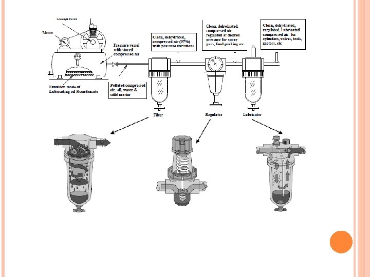
Air Service Equipment • The final stage of compressed air servicing or conditioning is a process carried out on the air supply, directly before its point of usage. • This process is accomplished by three devices 1. Filter 2. Regulator 3. Lubricator
• Three aims of the air service unit is: 1. to provide the air consuming equipment (actuators, motors, air tools and control circuit) with compressed air of suitable cleanliness. 2. should also provide pressure stabilized air at no more than the required maximum pressure. 3. it provides an air supply (flow), which carries lubricating oil in the correct adjusted quantities to lubricate valves, cylinders and motors.
detailed symbol With lubricator Without lubricator simplified symbol
Compressed air filter • An important role in determining the quality and performance of the working system which is to be supplied with compressed air. • The collected condensate must be drained before the level exceeds the maximum mark or level. • When the limit is reached a control piston opens a valve seat that ejects the condensate under air pressure via a drain line. • A further important characteristic of compressed air filters is the degree of separation, or efficiency, which indicates the percentage of particles of a particular size which can be separated out.
Compressed air filter
Compressed Air Pressure regulation Function: The function of the air pressure regulator is to maintain working pressure virtually constant regardless of fluctuations of the line pressure and air consumption. When the pressure is too low, it results in poor efficiencies and when the pressure is too high, energy is wasted and equipment’s performance decay faster. In pneumatic system, pressure fluctuations occur due to variation in supply pressure or load pressure. It is therefore essential to regulate the pressure to match the requirement of load regardless of variation in supply pressure or load pressure.
Generally pressure is regulated in pneumatic system at two places. ØAt the receiver tank Ø In the load circuits Pressure regulation at the receiver tank is required as a safety measure for the system. In the load circuits, pressure regulator is used to regulate the pressure for downstream components such as valves and actuators.
Types of Pressure regulator There are two types of Pressure regulators i) Diaphragm type regulator ii) Piston type regulator Diaphragm type regulator is commonly used in Industrial pneumatic system. There are two types of diaphragm type regulator i) Non- relieving or non-venting type. ii) Relieving or venting type is commonly used
Relieving or Venting Type Pressure regulator A Relieving type pressure regulator is shown in figure below, Outlet pressure is sensed by a diaphragm preloaded with a adjustable pressure setting spring. The compressed air , which flows through a controlled cross section at the valve seat, acts on the other side of the diaphragm. The diaphragm has large surface area exposed to secondary (outlet) pressure and is quite sensitive to its fluctuations. The movement of diaphragm regulates the pressure.
If the outlet pressure is low: whenever the more compressed air is consumed on secondary side or load side, then load pressure reduces. Therefore less force acts on diaphragm. The opposing higher spring force pushes the diaphragm in such a way as to move the valve disc more and permitting more air to flow to secondary side and thus increasing the pressure again. Pressure regulator: relieving
If the outlet pressure is high: whenever the less compressed air is consumed on secondary side or load side, then load pressure increases. Therefore more force acts on diaphragm. The opposing higher spring force pulls down the diaphragm in such a way as to move the valve disc less and permitting air to flow to vent hole and thus decreasing the pressure again Pressure regulator: relieving
Compressed Air lubricator The purpose of an oiler is to lubricate control devices and actuator. Oil is added by means of a standpipe and is dropped into the high velocity air stream where it is atomised.
Oil lubricator.
An Industrial compressed air system.