PNEUMATICS 101 FOR FRC 2017 An Introduction Mark


- Slides: 22
PNEUMATICS 101 FOR FRC 2017 An Introduction Mark Walker – FRC Team 2583 Based on Material from other teams (Thanks!) such as: Tim Serge FRC Team 836 Richard Bee FRC Team 4514 Team 358
What are we going to cover? ■ “What do you want to know? (or What do you already know? ) ■ What is pneumatics? ■ Why choose pneumatics in your robot design? ■ How to select the right components. ■ Putting it all together ■ Tips and recommendations.
What is pneumatics? ■ Use of fluid to transmit power and multiply force. ■ Hydraulics – uses non-compressible fluid such as oil ■ Pneumatics – uses compressible gas – e. g. air ■ In FRC, pneumatics allows stored air pressure to drive actuators
Why Choose Pneumatics? ■ Advantages – Actuation can be fast – Can be used in compact environments – Reliable – Consistent movements ■ Disadvantages – Weight of compressor (2. 76 lb) and components – Can overheat – Compressor takes time to replenish air – Potential battery drain
Safety is imperative! ■ Pressurized devices can explode if overfilled. ■ Make sure all components meet specs (120 psig operating) and are properly adjusted. ■ Make sure safety pressure relief valve is properly calibrated. ■ Watch out for power on/power off actions – actuators may suddenly extend or retract ■ Design for safety!
Basic Components in FRC pneumatics
Pneumatic Control Module ■ Controls Compressor ■ Powers and Controls Solenoids (12 or 24 v) ■ Wired to robo. RIO for control, PDP for power.
How to choose right pneumatic design? ■ Usually not efficient to have only a single pneumatic actuator – Compressor, storage and component weight disadvantage too great ■ Do you require a simple linear motion? – Shifting gears – Closing a grabber – Moving a lever (possibly generate mechanical advantage)
Incorporate Mechanical Advantage into design
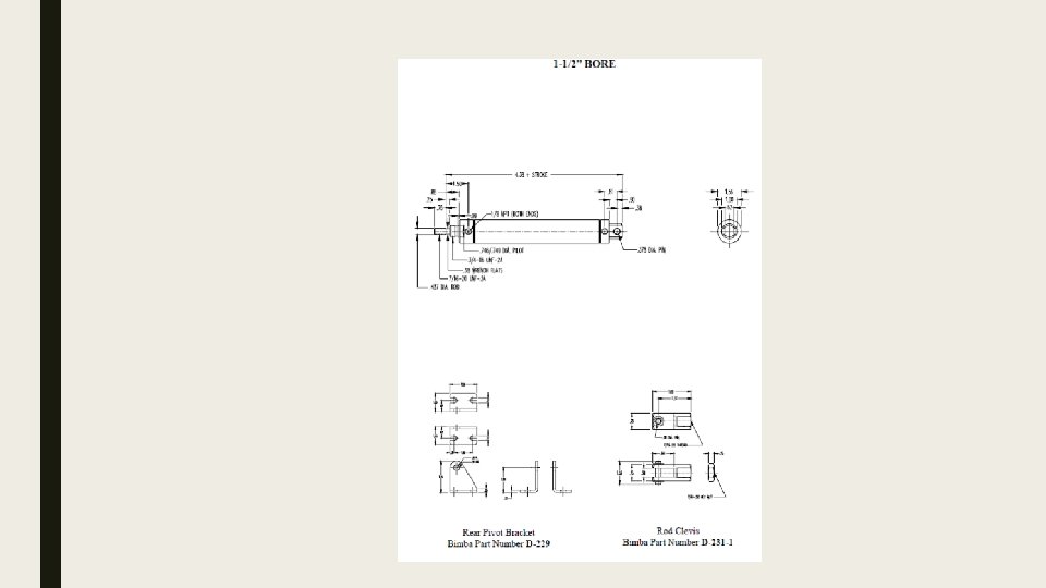
Air Cylinder • Determine the inside diameter from the cylinder specifications • Know the diameter of the plunger rod • Area going “out” is greater than going “in” • So Force will be different also. • Can use bleeder valves to adjust particular lines to reduce pressure.
Types of Actuators ■ Single Action – spring return – Air pressure extends – Spring returns – Single port solenoid – Air pressure must overcome spring – May save 50% air ■ Double Action – Air pressure returns – Air pressure extends & Returns – Double port solenoid – Air pressure less – Uses more air – Can adjust return force
How much force can I generate? ■ FRC Rules: – Compressor storage loop is max 120 psig – Working loop is max 60 psig ■ Can use loops with less pressure (e. g. 30 psig) ■ Force is determined by multiplying pressure by area over which it is applied – F=p*A
Example: pressure in 2” Cylinder at 60 psig Ao = π * 12 Ao = 3. 14 in 2 AI = Ao – π * (1/2)2 AI = 3. 14 -. 79 = 2. 35 in 2 Fo = 60 psig * 3. 14 in 2 = 188. 4 lbf
Determine Cylinder size and pressure based on desired force ■ If you determine you need 24 lbf to move an object you can work backwards to determine the cylinder bore required at 30 lbf or 60 lbf. ■ Per Bimba, add a design factor of 1. 25 to desired pressure to compensate for friction. ■ Add a speed factor of 1. 25 to 2. 00 to increase actuation speed (<4 in/sec >16 in/sec)
Putting it all together ■ The 2017 FRC Control System makes pneumatics straight forward. ■ Install PCM – Wire to PDP – Wire to CAN network ■ Wire Compressor and pressure switch to PCM ■ PCM can drive either 12 v or 24 v solenoids (but not at the same time) – Use jumper to set ■ Each solenoid wired from PCM port 0 -7
Air Circuit ■ Follow FRC guidance to create High Pressure and Low Pressure Circuits ■ High pressure includes storage – Must have Norgren pressure relief valve(calibrate!) – Must have dump valve to depressurize system ■ Primary pressure regulator reduces pressure to low pressure circuit (60 psig) ■ Secondary pressure regulator(s) can reduce further ■ All pressure gauges and dump valve must be easily viewable and accessible to inspectors and referees.
Basic Components in FRC pneumatics
Tips ■ Fittings – – Use Teflon tape – leave at least one thread showing – Use tube cutter to make clean cuts perpendicular to tube axis – Fittings are tapered National Pipe Thread fittings – don’t over torque ■ Sizing – Consider how often actuator will fire – Add up volume of air used each time – Compare to amount stored and generated – Can precisely calculate using Ideal Gas Law for Adiabatic case (with absolute temperature and pressure)
Software ■ Labview, Java and C++ libraries have functions to control compressor and solenoids ■ In Labview, start compressor in Begin; – Solenoids are specified and “set->on” or “set->off” or forward/reverse to actuate – If other parts of the robot have critical functions that could be harmed by compressor starting, can stop/start to prevent
References ■ 2017 Pneumatics Manual from FRC ■ This presentation: http: //www. team 2583. org/? ? ? ■ Good explanations by Hauppauge Robotic Eagles http: //team 358. org/files/pneumatic/ ■ Suppliers – Bimba – http: //www. bimba. com – Andy. Mark http: //www. andymark. com/Pneumatics-s/398. htm – SMC (solenoids) – Cross the Road Electronics – Festo – Parker Fittings
Additional Material