FRC Pneumatics Air Safety I know what were


 so compressor")


 Pneumatics rules are very")

- Slides: 24
FRC Pneumatics Air Safety
I know what we’re going to do today! What are pneumatics? Pneumatics system components FRC Pneumatics rules and layout Wildstang conventions
What is this ‘Pneumatics’ you speak of? Pneumatics systems use compressed gases to cause mechanical motion For our purposes, we use compressed air Our use for mechanical motion varies: • Small things: shifting gearboxes • Large things: robot appendages
A Basic Pneumatics System Air tank Pressure switch Compressor High Pressure Release valve Regulator Low Pressure Cylinder/Piston Valve
Pneumatics System Components Compressor Pressure relief valve Pressure switch Air tanks Regulator Ball valve (air pressure release) Electric valves Connectors & fittings Tubing Cylinders/pistons
Safety first We are dealing with high pressure air System awareness and safety is critical Always check with a mentor if you suspect a component is damaged Be aware of moving parts Always check before operating any pneumatic parts Example: At 60 psi, a 1½” bore cylinder will exert ~100 lbs force, a 2” bore cylinder will exert ~190 lbs force
Safety Always wear your safety glasses. The compressor gets extremely hot, do not touch it after it has been running. Air tanks can explode.
Compressor This is the source of our compressed air Compressors have different flow rate – a measurement of their ability to output air Standard FRC kit compressor is 1. 03 cfm, max working pressure of 120 psi Compressors get hot! This is the “heart” of the Pneumatic system
Pressure Relief Valve Adjustable relief valve For FRC, is mounted directly onto compressor When pressure reaches valve’s limit, air is released Safety mechanism that prevents overpressure situation When pressure exceeded, it’s the path of least resistance
Pressure Switch contacts open at around 115 psi Switch contacts close at around 95 psi Connects to digital input on sidecar Allows software to turn compressor on and off to keep system charged at max allowed pressure Basically, it functions as a gauge for software
Air Tanks Air tanks store compressed air Store high-pressure air (~120 psi) so compressor does not need to run continuously These should be before the primary regulator Number and size of tanks, and cylinder sizes and use, impacts how much the compressor runs
Regulator Primary regulator is a Norgren relieving regulator Limits the downstream pressure to 60 psi. It changes High→Low pressure Max downstream pressure is adjustable Need to adjust to stay within rules If you imagine your sink faucet, it’s the same principle
Ball valve This valve is used to release all pressure in the system Must be installed in a location that can release all system pressure when opened Needs to be easy to reach Absolute seal
Gauges These are a visual aid that allow you to see if the pressure is dropping anywhere in the system. 2 different gauges within the system.
Electric Valves allow the air to flow to the cylinders Valves have 1 input, 2 outputs, and at least one escape Electrically operated via c. RIO solenoid module The 2 outputs go to the front and rear cylinder input The exhaust is left open
Electric Valves we use are 1 -way or 2 -way 1 -way valves have a default position • When no signal is applied (robot is disabled) valve returns to default position • Useful for things to ‘let go’ 2 -way valves do not have a default position • They keep their last position when robot is disabled
Connectors & fittings Many different types of connectors Some thread directly into tanks and cylinders All use push-to-connect fitting to attach hose Always push tube in hard until you feel it connect Always push to release hose from fitting
Tubing carries the pressurised air through the system Tube must have very straight cuts to connect properly in fittings • Angles lead to leaks or tube popping out
Cylinders make things go Air inlet at rear and front of cylinder to push piston out or in Air pushed out of the cylinder is released through the valve escape port Come in a variety of bore (diameter) and stroke (length) Can connect 2 cylinders to outputs of 1 valve “Pneumatic muscle”
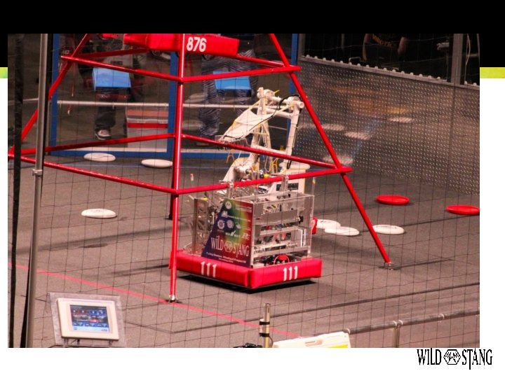
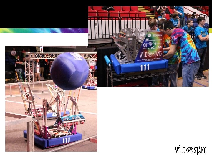
Whole FRC Pneumatics System
FRC Pneumatic Rules can change each year (like any rules) Pneumatics rules are very specific (for safety) • Max ratings of components and system • Use of regulators and gauges • Stored and working pressure, and what can be used on each side • Plumbing restrictions • Etc.
Wildstang Conventions Colour codes • White + other colour for pneumatics Colour code wire and valve for each circuit Tubing colours • Solid yellow for high pressure • Other colours for low pressure • In 2012 used blue from regulator to valve, and green from valve to cylinder • Easy to identify high or low pressure, or pre/post valve