cephalometric radiograph is a diagnostic radiography as a


 that is a head-holding")
To enable the identification of cephalometric points and planes used in")


 containing intensifying screens and indirect action film.")


 pencil to outline the following : 1. Soft tissue profile")


- Slides: 36
cephalometric radiograph
is a diagnostic radiography, as a standardized and radiographic form of skull radiography used extensively in orthodontics to assist the relationships of the teeth to the jaws and the jaws to the rest of the facial skeleton.
Standardization was essential for the development, the measurement and comparison of specific points, distances and lines within the facial skeleton, which is now an integral part of orthodontic assessment. The greatest value is probably obtained from these radiographs if they are traces or digitized and this is essential when they are used for the monitoring of treatment progress.
Cephalometric x-rays are also used by otolaryngologists doctors who specialize in the treatment of ear, nose and throat disorders such as sleep apnea because these x-rays provide a view of the patient's airways.
A radiograph of the head taken in a Cephalometer (Cephalostat) that is a head-holding device introduced in 1931 by B. H. Broadbent in the USA and by H. Hofrath in Germany. The original design included two ear rods for insertion into the external auditory canals, an infraorbital pointer and a forehead clamp, to achieve parallelism of the Frankfort plane with the floor. The concept of natural head position was introduced by C. F. A. Moorrees and M. R Kean in 1958 and now is a common method of head orientation for cephalometric radiography.
Aims of Practical a)To enable the identification of cephalometric points and planes used in orthodontic diagnosis and treatment planning. b)To trace 2 lateral skull radiographs (before and after treatment) of orthodontic treatment using a functional appliance and to identify the changes achieved (if any).
Main indications: 1. orthodontic treatment 2. orthognathic srgey
Orthodontics: Intial diagnosis confirmation of the underlying skeletal and or soft tissue abnormalities. Treatment planning. Monitoring treatment progress e, g, to assess anchorage requirements and incisor inclination. Appraisal of treatment result e. g. 1 or 2 months before the completion of active treatment to ensure that treatment targets have been met and to allow planning of retention.
Orthognatic surgery: Preoperative evaluation of skeletal and soft tissue patterns To assist in treatment planning Postoperative appraisal of the results of surgary Long term follow up studies.
Equipment Several different types are available for cephalometric radiography, either as seprate units, or as additional attachment, the patients are seated, while in these they remain standing.
1. Head positioning and stabilizing apparatus with ear rods to ensure a standardized patient position (some units also have infraorbital guide rods). 2. Fixed anti-scatter grid to stop photons scatter within the patient reaching the film and degrading the final image.
3. Cassette holder: Cassette (usually 18*24 cm) containing intensifying screens and indirect action film. Aluminium wedges filter. This is either part of ceophalosat and positioned between the patient and the anterior part of the cassette, or it is attached to the tubehead, covering the anterior part of the emerging beam. Its function is to attenuate the X=ray selectively in the region of the facial soft tissue because these tissues are not dense enough on their own to produce a visible radiographic shadow. This added attention enable the soft tissue profile to be seen on the final radiograph.
4. X-ray generating apparatus that should be: In a fixed position relative to the cephalostat (approx. 2 cm) and the film so that successive radiographs are reproducible and comparable. Capable of producing an X-ray beam that is: Sufficiently penetrating to reach the film. Parallel in nature to minimize magnification between R and L sides of the mandible and to ensure that the midline points S, N and A are as sharp as possible. Collimated to an approximately triangular shape to restrict the area of the patient irradiated to the required cranial base and facial skeleton, so avoiding the skull vault and cervical spine.
Concentrating on the patient's profile or side view of the head the x-ray technician positions the patient according to specific criteria necessary when taking a cephalometric x-ray. The exposure takes approximately 10 seconds and the x-ray is developed in approximately five to six minutes. Most dental offices are equipped with the equipment necessary to take a cephalometric x-ray.
True cephalometric lateral skull Cephalometric postero-anterior of the jaws
True cephalometric lateral skull
The terminology used lateral skull projection is somewhat confusing, the adjective true, as opposed to oblique, being used to describe lateral skull projection
The film is parallel to the sagittal plane of the patient's head. The X-ray beam is perpendicular to film and sagittal plane.
In addition, the word cephalometric should be include when describing the true lateral skull radiograph taken in the cephalostat. This enables differentiation from the non-standardized true lateral skull projection taken in a skull unit.
The technique and position: The patient is positioned within the cephalostat, with the sagittal plane of the head vertical and parallel to the film and with the Frankfort plane horizontal. This positions the patient with their head oriented at 90 o to the X-Ray beam at a distance of 5 ft (152. 4 cm) or 150 cm from the tube. The film is placed 15 inches from the head. The beam most commonly enters on the patient’s right side, with the film cassette adjacent to the patient’s left side (so that the patient’s head is oriented to the right on the radiograph), but the reverse convention also is used. The teeth should generally be in maximum intercuspation. The head is immobilized carefully within the apparatus with the plastic ear rods being inseted into the external auditory meati. The aluminium wedge is positioned to cover the anterior part of the film. The equipment is designed to ensure that when the patient is positioned correctly, the X -ray beam is horizontal and centered on the ear rods.
To accomplish natural head position, the patient is asked to look into a mirror placed in front of him/her at eye level (as if he/she were looking at the horizon), with the interpupillary line parallel to the floor.
Cephalometric postero-anterior of the jaws
This projection is identical to the PA view of the jaws, that it is standardized and reproducible. This makes it suitable for the assessment of facial asymmetries and for preoperative and postoperative surgery involving the mandible.
Technique and positioning: The head stabilizing apparatus of the cephalostat is rptated through 90 o. The patient is positioned in the apparatus with the head tipped forwards and with the radiographic baseline, i. e. in the forehead-nose position. The head is immobilized within the apparatus by inserting the plastic ear rods ito the external auditory meati. The fixed X-ray beam is horizontal with the central ray centered through the cervical spine at the level of the rami of the mandible.
Tracing technique
The film is then traced and various standard landmarks, lines and angles are measured and recorded. This allows comparison with normal values for a population and assessment of growth and/or effects of treatment. For the purposes of this practical we will use a set of analysis widely used in orthodontics. It is known as 'Eastman Analysis'
This should be undertaken in a darkened room. Use good quality tracing paper securely taped to radiograph (along the top edge of the tracing paper, directly to the radiograph - this allows the tracing paper to be lifted to examine the radiograph directly, yet replace it in the same place for tracing)
Use a sharp (HB) pencil to outline the following : 1. Soft tissue profile of face (forehead to chin) 2. Sella turcica 3. Frontal bone and nasal bone 4. Orbital floor 5. External auditory meatus 6. Maxilla, upper lst molar and upper central incisor 7. Mandible, mandibular symphysis, lower lst molar and lower central incisor
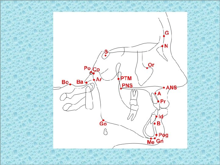
Cephalometric landmarks
Readily recognizable points on a cephalometric radiograph or tracing, representing certain hard or soft tissue anatomical structures (anatomical landmarks) or intersections of lines (constructed landmarks). Landmarks are used as reference points for the construction of various cephalometric lines or planes and for subsequent numerical determination of cephalometric measurements.
Next Identify and mark the following cephalometric points: S Sella: Mid point of sella turcica N Nasion: Most anterior point on fronto-nasal suture Or Orbitale: Most inferior anterior point on margin of orbit Po Porion: Upper most point on bony external auditory meatus ANS Anterior Nasal Spine PNS Posterior Nasal Spine Go Gonion: Most posterior inferior point on angle of mandible Me Menton: Lower most point on the mandibular symphysis A point: Position of deepest concavity on anterior profile of maxilla B point: Position of deepest concavity on anterior profile of mandibular symphysis
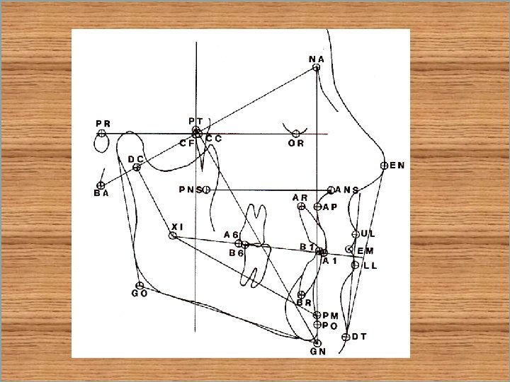
Then draw in the following lines/planes Frankfort Plane Po - Or Equivalent to the true horizontal when patient is standing upright. Maxillary Plane PNS - ANS Gives inclination of maxilla relative to other lines/planes. Mandibular Plan Go - Me Gives inclination of mandible relative to other lines/planes. The angle MMPA - Maxilla to Mandibular Planes Angle (Maxillary plane to Mandibular plane) Gives an inclination of the maxilla relative to the mandible, this in turn indicates the relative proportions of face height and acts as an indicator future growth direction. S - N Line: Indicates orientation of anterior cranial base. N - A indicates relative position of maxilla the cranial base N - B indicates relative position of maxilla the cranial base The angles SNA; SNB; ANB indicates relative position of maxilla/mandible to each other and to the cranial base Long axis of upper central incisor/lower central incisor (root apex to incisal edge) - allows measurement of the angulation of incisors to maxilla/mandibular planes.
THANK YOU FOR LISTENING