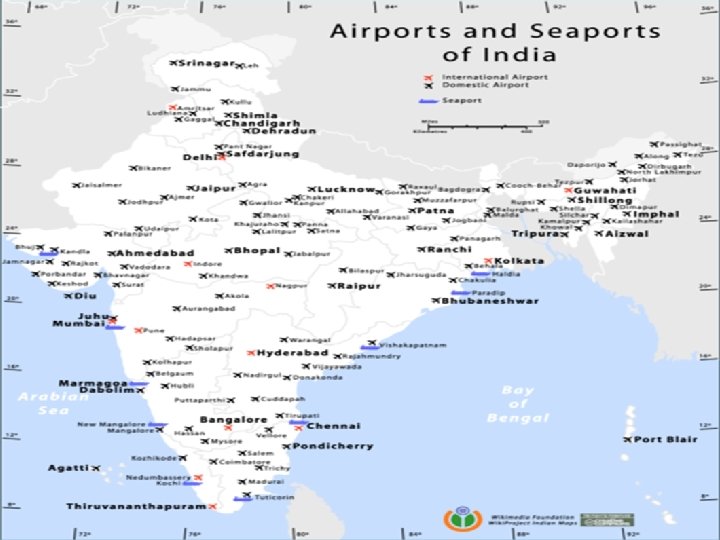
AERODROME IN INDIA THERE ARE 30 MAJOR AIRPORTS


")


 • The geographical coordinates of each threshold shall")
 • The geographical coordinates of significant obstacles in")
 • Pre-flight altimeter check location • Declared distances")
 • Visual approach slope indicator systems – associated")
")
 Latitude")


 is defined as the length of runway available for the ground run of")
 is defined as the length of runway available for the ground run of")
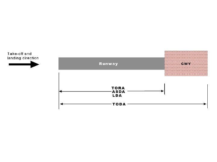
. For TODA having an obstacle clear gradient")


- Slides: 48
AERODROME
IN INDIA THERE ARE 30 MAJOR AIRPORTS AND THERE ARE 193 AIR CONSTRUCTIONS. v v v v TAMIL NADU 12 ANDRA PRADESH 16 KARNATAKA 16 KERALA 5 ORISSA 5 PUDUCHERRY 1 UTTAR PRADESH 11 v v v CHENNAI—INTERNATIONAL AIRPORT ARAKKONAM—NAVAL AIR BASE CHENNAI—AVADI AIR FORCE BASE CHENNAI—AIR FORCE STATION COIMBATORE—AIRPORT SULUR—AIR FORCE BASE MADURAI—AIRPORT SALEM—AIRPORT THANJAVAUR—AIR FORCE BASE TIRUCHIRAPALI—AIRPORT THOOTHUKUDI—AIRPORT VELLORE—AIRPORT
CONTENTS • • • Aerodrome data Basic terminology Aerodrome reference code Aerodrome reference point Aerodrome elevation Aerodrome reference temperature
‘WHICH CAME FIRST? ’ • chicken or an egg? Not that notorious question its aerodrome or aircraft? • Obviously aircraft came first • The aviator first constructed an aeroplane, and then began to search for a suitable ‘airfield’, where he can test it. • The aerodrome parameters had to be selected on the basis of performance and geometrical characteristics of the aircraft.
• The first aeroplanes were light, with a tail wheel, and the engine power was usually low. • A mowed meadow with good water drainage was sufficient as an aerodrome for those aeroplanes. • the surrounding airspace to be free of obstacles over a relatively wide area. • The main change in the airfield’s physical characteristics was the runway length. • The multiengine aircraft required the length to increase to approximately 1 000 m.
• Jet aircraft required further extension of the runway, together with increases in its width and upgrading its strength. • The increasing number of aircraft, and the training of the military pilots required more support facilities at airfields, such as hangars, workshops and barracks. • According to Boeing, air traffic will double by 2020 and new runways will be needed at 60 of the world’s largest airports by 2025. • Boeing predicts that the world aircraft fleet will double by 2025 and estimates a need for approximately 27 200 new commercial airplanes
ICAO REGULATION • Safety is the overriding requirement in aviation. Standardisation is one of the means to achieve it. • In the case of airports, it is standardisation of facilities, ground equipment and procedures. • AWOP All Weather Operations Panel–issues of operations under restricted meteorological conditions • VAP Visual Aids Panel–visual aids of airports • OCP Obstacle Clearance Panel
Cont… • ARCP Aerodrome Reference Code Panel–method for interrelating specifications of airports • HOP Helicopter Operations Panel–operation of helicopters. • ICAO languages (English, French, Spanish or Russian) • STANDARDS contain specifications for some physical characteristics, configuration, materials, performance, personnel or procedures. • Annex 14, include guidelines for aerodrome design, construction, planning and operations.
MANUALS Aerodrome Design Manual • Part 1 - Runways • Part 2 - Taxiways, Aprons and Holding Bays • Part 3 - Pavements • Part 4 - Visual Aids • Part 5 - Electrical Systems Airport Planning Manual • Part 1 - Master Planning • Part 2 - Land Use and Environmental Control • Part 3 - Guidelines for Consultant/Construction Services
Airport Services Manual • Part 1 - Rescue and Fire Fighting • Part 2 - Pavement Surface Conditions • Part 3 - Bird Control and Reduction • Part 4 - Fog Dispersal • Part 5 - Removal of Disabled Aircraft • Part 6 - Control of Obstacles • Part 7 - Airport Emergency Planning • Part 8 - Airport Operational Services • Part 9 - Airport Maintenance Practices
AERODROME DATA • • • Aerodrome design Aerodrome administration Aerodrome location Movement area Lighting systems Navigation aids Rescue and fire-fighting services Ground services Special procedures
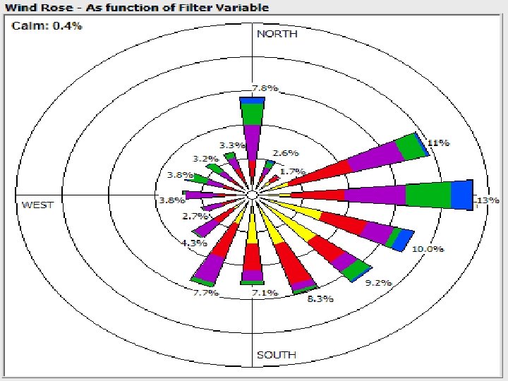
WIND ROSE • A wind rose graphically depicts wind velocities, directions, and their probability of occurrence in a format resembling a compass
AERODROME REFERENCE CODE
Aerodrome Reference Point • An aerodrome reference point shall be established for an aerodrome. • The aerodrome reference point shall be located near the initial or planned geometric centre of the aerodrome and shall normally remain where first established. • The position of the aerodrome reference point shall be measured and reported to the aeronautical information services authority in degrees, minutes and seconds.
Example Al Najaf Al-Ashraf International Airport Aerodrome Reference Point coordinates N 31º 59. 4’, E 044 º 24. 2’
Aerodrome elevation • The aerodrome elevation and geoid undulation at the aerodrome elevation position shall be measured to the accuracy of one-half metre or foot and reported to the aeronautical information services authority. • For an aerodrome used by international civil aviation for non-precision approaches, the elevation and geoid undulation of each threshold, the elevation of the runway end any significant high and low intermediate points along the runway shall be measured to the accuracy of one-half metre or foot and reported to the aeronautical information services authority. • For precision approach runway, the elevation and geoid undulation of the threshold, the elevation of the runway end and the highest elevation of the touchdown zone shall be measured to the accuracy of one-quarter metre or foot and reported to the aeronautical information services authority.
Example Al Najaf Al-Ashraf International Airport Elevation 32. 9 M (108 ft)
Aerodrome reference temperature • An aerodrome reference temperature shall be determined for an aerodrome in degrees Celsius. • The aerodrome reference temperature shall be the monthly mean of the daily maximum temperatures for the hottest month of the year (the hottest month being that which has the highest monthly mean temperature). This temperature shall be averaged over a period of years.
Example Al Najaf Al-Ashraf International Airport Reference Temperature 43. 8 ºC
Aerodrome dimensions and related information • The following data shall be measured or described, as appropriate, for each facility provided on an aerodrome: – – – – – runway C true bearing to one-hundredth of a degree, strip runway end safety area stopway, taxiway C designation, width, surface type; apron C surface type, aircraft stands; the boundaries of the air traffic control service; clearway C length to the nearest metre or foot, ground profile; visual aids for approach procedures, location and radio frequency of any VOR aerodrome check-point; location and designation of standard taxi-routes; distances to the nearest metre or foot of localizer and glide path elements comprising an instrument landing system (ILS)
Aerodrome dimensions and related information (Cont) • The geographical coordinates of each threshold shall be measured and reported to the aeronautical information services authority in degrees, minutes, seconds and hundredths of seconds. • The geographical coordinates of appropriate taxiway centre line points shall be measured and reported to the aeronautical information services authority in degrees, minutes, seconds and hundredths of seconds. • The geographical coordinates of each aircraft stand shall be measured and reported to the aeronautical information services authority in degrees, minutes, seconds and hundredths of seconds.
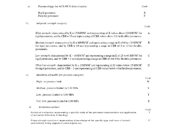
Aerodrome dimensions and related information (Cont) • The geographical coordinates of significant obstacles in the approach and take-off areas, in the circling area and in the vicinity of an aerodrome shall be measured and reported to the aeronautical information services authority in degrees, minutes, seconds and tenths of seconds. • The bearing strength of a pavement intended for aircraft of ramp mass greater than 5 700 kg shall be made available using the aircraft classification number C pavement classification number (ACN-PCN) method by reporting all of the following information: – the pavement classification number (PCN); – pavement type for ACN-PCN determination; – subgrade strength category; – maximum allowable tire pressure category or maximum allowable tire pressure value; and – evaluation method.
Aerodrome dimensions and related information (Cont) • Pre-flight altimeter check location • Declared distances – take-off run available; – take-off distance available; – accelerate-stop distance available; and – landing distance available. • Condition of the movement area and related facilities – construction or maintenance work; – rough or broken surfaces on a runway, a taxiway or an apron; • Water on a runway • Snow, slush or ice on a runway • Disabled aircraft removal • Rescue and fire fighting
Aerodrome dimensions and related information (Cont) • Visual approach slope indicator systems – associated runway designation number; – For an AT-VASIS, PAPI or APAPI installation, the side of the runway on which the lights are installed, i. e. left or right, shall be given; – nominal approach slope angle(s). – minimum eye height(s) over the threshold of the on-slope signal(s). • Coordination between aeronautical information services and aerodrome authorities – information on aerodrome conditions – the operational status of associated facilities, services and navigation aids within their area of responsibility; – any other information considered to be of operational significance.
Example Of Aerodrome Data Dunsfold Aerodrome (UK)
Communications General Info Country United Kingdom ICAO ID EGTD Time UTC 0(+1 DT) Latitude 510702 N Longitude 003209 W Elevation 172 feet amsl Magnetic Variation 4° W Operating Agency Dunsfold Park Ltd Private Unlicensed Aerodrome Operating Hours PPR: By appointment only Contact +44 (0)1483 200 900 - Dunsfold Radio 119. 100 Mhz (Air / Ground) Runways ID Dimensions Surface PCN ILS 07/25 1880 x 45 M ASPHALT 30 No Lighting ID Approach Threshold Runway 07/25 Yes Yes Fuel Jet A 1 Available Avgos Available Joining Instructions Communications PPR - Aircraft should call “DUNSFOLD RADIO” (119. 100 Mhz) at the earliest opportunity when inside 10 nm of the aerodrome Circuit Pattern Runway 07 – right hand Runway 25 – left hand Circuit Height 1000 ft QNH Navigation Warnings At both ends of Runway 07/25 its width is twice that of the associated edge lights due to extra pavement at one side. Since runway centre lighting is not installed, pilots should ensure that they are correctly lined up The base of the London TMA overhead is 2, 500 ft The London Gatwick CTA is 1 nm east of the aerodrome On occasions, high performance military aircraft operate to and from Dunsfold Aerodrome
Minimum distance between parallel runways Where parallel non-instrument runways are intended for simultaneous use, the minimum distance between their centre lines shall be: • 210 m where the higher code number is 3 or 4; • 150 m where the higher code number is 2; and • 120 m where the higher code number is 1.
NATURE OF RUNWAY SURFACE • The runway length determines the types of aircraft that may use the • aerodrome, their allowable take-off mass and hence the distance they may fly. The runway surface type must be notified as • bitumen seal; • asphalt; • concrete; • gravel; • grass; or • natural surface.
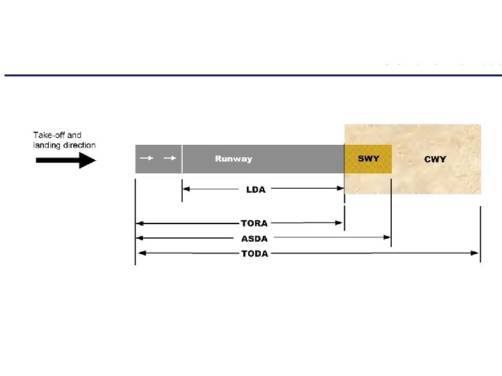
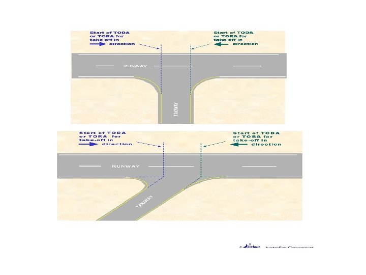
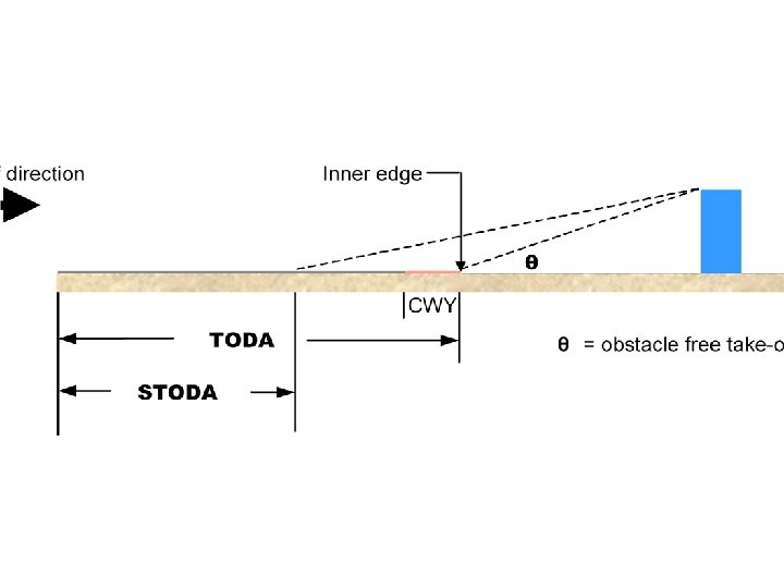
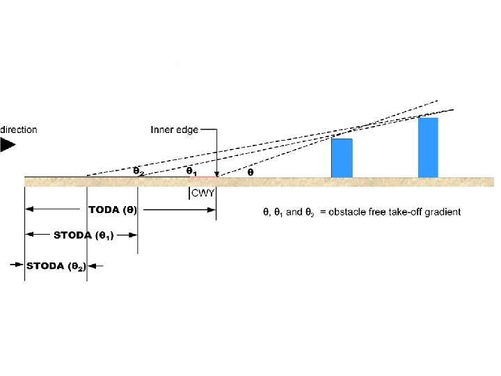
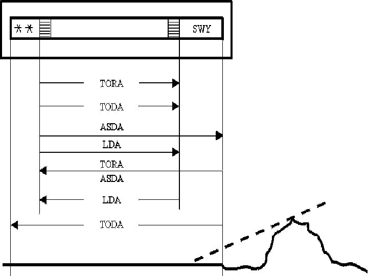
DECLARED DISTANCES • Declared distances are the available operational distances notified to a pilot for take-off, landing or safely aborting a take-off. These distances are used to determine whether the runway is adequate for the proposed landing or take-off or to determine the maximum payload permissible for a landing or take-off. • take off run available (TORA); • take off distance available (TODA); • accelerate-stop distance available (ASDA); • landing distance available (LDA);
(TORA) is defined as the length of runway available for the ground run of an aeroplane taking off. This is normally the full length of the runway; neither the SWY nor CWY are involved. (TODA) is defined as the distance available to an aeroplane for completion of its ground run, lift-off and initial climb to 35 ft. This will normally be the full length of the runway plus the length of any CWY (ASDA) is defined as the length of the take-off run available plus the length of any SWY. Any CWY is not involved. ASDA = TORA + SWY
(LDA) is defined as the length of runway available for the ground run of a landing aeroplane. The LDA commences at the runway threshold
• Supplementary take-off distances available (STODA). For TODA having an obstacle clear gradient of more than 1. 6%, STODA must be provided, except if the STODA is less than 800 m. STODA must be provided for obstacle clear take-off gradients of 1. 6%, 1. 9%, 2. 2%, 2. 5%, 3. 3% and 5%, up to the gradient associated with TODA. In calculating STODA, care must be taken to ensure that a shielded object does not become critical for the lesser take-off distances
Al Najaf Al-Ashraf International Airport Main Apron: Concrete PCN-43/F/C/W/T
RUNWAY WIDTH • the distance between the outside edges of the main gear wheels • the distance between wing mounted engines and the longitudinal axis of an aeroplane • the wing span
Width of runways • The width of a runway shall be not less than the appropriate dimension specified in the following tabulation:
Example Al Najaf Al-Ashraf International Airport 1 RWY 10 28 2 BRG True and Mag 100 T / 96 º-16’M 280 T / 276 º -16’M 3 RWY dimensions 9. 842 ft x 147. 6 ft 3000 m x 45 m 4 PCN 43 43 5 THR Coordinates 6 THR Elevation 115. 932 ft 89. 986 ft 7 Slope of RWY/SWY Unknown 8 SWY Dimensions Unknown 9 CWY Dimensions Unknown 10 Strip Dimensions Not calculated 11 Obstacle free zone Not calculated N 31 º 59’ 35’’ E 044 º 23’ 20’’ N 31 º 59’ 11’’ E 044 º 25’ 10’’
THANK YOU