UNIT 5 Wind direction indicator Wind direction indicator


 runways the markings of the")


 of markings less than 900 m 1 900")


- Slides: 44
UNIT 5
Wind direction indicator
Wind direction indicator • An aerodrome shall be equipped with at least one wind direction indicator. • A wind direction indicator shall be located so as to be visible from aircraft in flight or on the movement area and in such a way as to be free from the effects of air disturbances caused by nearby objects.
Wind direction indicator • The location of at least one wind direction indicator should be marked by a circular band 15 m in diameter and 1. 2 m wide. • Provision should be made for illuminating at least one wind indicator at an aerodrome intended for use at night.
Landing direction indicator
Landing direction indicator • Where provided, a landing direction indicator shall be located in a conspicuous place on the aerodrome. • The landing direction indicator should be in the form of a “T”.
Signalling lamp • A signalling lamp shall be provided at a controlled aerodrome in the aerodrome control tower. • A signalling lamp should be capable of producing red, green and white signals, and of: – Being aimed manually at any target as required; – Giving a signal in any one colour followed by a signal in either of the two other colours; and – Transmitting a message in any one of the three colours by Morse Code up to a speed of at least four words per minute. • The beam spread should be not less than 1° nor greater than 3°, with negligible light beyond 3°. • When the signalling lamp is intended for use in the daytime the intensity of the coloured light should be not less than 6000 cd.
Signalling lamp
Signal panels and signal area • The signal area should be located so as to be visible for all angles of azimuth above an angle of 10° above the horizontal when viewed from a height of 300 m. • The signal area shall be an even horizontal surface at least 9 m square. • The colour of the signal area should be chosen to contrast with the colours of the signal panels used, and it should be surrounded by a white border not less than 0. 3 m wide.
Signal Area • The signals that must be displayed are a white cross if the aerodrome is unserviceable. • A white dumb-bell if aircraft are only to use sealed movement areas. • A white double-cross when glider operations are being conducted. • In a major gliding centre, the double cross symbol is permanently displayed.
Signal Area
Markings
Runway
General • At an intersection of two (or more) runways the markings of the more important runway, except for the runway side stripe marking, shall be displayed and the markings of the other runway(s) shall be interrupted. • The order of importance of runways for the display of runway markings should be as follows: – Precision approach runway; – Non-precision approach runway; and – Non-instrument runway. • Runway markings shall be white.
General
General • Taxiway markings, runway turn pad markings and aircraft stand markings shall be yellow. • Apron safety lines shall be of a conspicuous colour which shall contrast with that used for aircraft stand markings. • At aerodromes where operations take place at night, pavement markings should be made with reflective materials designed to enhance the visibility of the markings.
Runway designation marking • A runway designation marking shall be provided at the threshold of a paved runway. • A runway designation marking shall consist of a two-digit number and on parallel runways shall be supplemented with a letter. – for two parallel runways: "L" "R"; – for three parallel runways: "L" "C" "R"; – for four parallel runways: "L" "R"
Runway designation marking
Runway Centre Line Marking • A runway centre line marking shall be provided on a paved runway. • A runway centre line marking shall be located along the centre line of the runway between the runway designation markings, except when interrupted. • A runway centre line marking shall consist of a line of uniformly spaced stripes and gaps.
Runway Centre Line Marking
Threshold marking • A threshold marking shall be provided at the threshold of a paved instrument runway, and of a paved non-instrument runway where the code number is 3 or 4 and the runway is intended for use by international air transport.
Threshold marking
TRANSVERSE STRIPE • Where a runway threshold is temporarily displaced from the extremity of a runway, a transverse stripe should be added to the threshold marking. • A transverse stripe shall be not less than 1. 80 m wide.
ARROWS • When a runway threshold is temporarily displaced from the normal position, it shall be marked. • All markings prior to the displaced threshold shall be obscured and the runway centre line marking converted to arrows.
Aiming Point Marking • An aiming point marking shall be provided at each approach end of a paved instrument runway where the code number is 2, 3 or 4. • The aiming point marking shall commence no closer to the threshold than the distance indicated in the appropriate column
Aiming Point Marking Location and Dimensions of the Aiming Point Marking a. The greater dimensions of the specified ranges are intended to be used where increased conspicuity is required. b. The lateral spacing may be varied within these limits to minimize the contamination of the marking by rubber deposits. c. These figures were deduced by reference to the outer main gear wheel span which is element 2 of the aerodrome reference code at Subpart D, Table 1 -1.
Touchdown zone marking • A touchdown zone marking shall be provided at each end of a paved runway where the code number is 3 or 4. • A touchdown zone marking shall consist of pairs of rectangular markings symmetrically disposed about the runway centre line with the number of such pairs related to the landing distance available and, where the marking is to be displayed at both the approach directions of a runway,
Touchdown zone marking Runway length Pair(s) of markings less than 900 m 1 900 m up to but not including 1200 m 2 1200 m up to but not including 1500 m 3 1500 m up to but not including 2400 m 4 2400 m or more 6
Runway Side Stripe Markings • A runway side stripe marking shall be provided between the thresholds of a paved runway where there is a lack of contrast between the runway edges and the shoulders or the surrounding terrain. • A runway side stripe marking shall consist of a stripe placed along each edge of the runway.
Aiming point, touchdown zone markings and Runway Side Stripe Markings
Taxiway Centre Line Marking • Taxiway centre line marking shall be provided on a paved taxiway, and apron where the code number is 3 or 4 in such a way as to provide continuous guidance between the runway centre line and aircraft stands. • A taxiway centre line marking shall be at least 15 cm in width and continuous in length except where it intersects a taxi-holding position marking or taxiway intersection marking or when interrupted by an information marking
Taxiway Intersection Marking • A taxiway intersection marking should be displayed at an intersection of two paved taxiways where it is desired to designate a specific holding limit. • A taxiway intersection marking shall consist of a single broken line
Runway turn pad marking • Where a runway turn pad is provided, a runway turn pad marking shall be provided for continuous guidance to enable an aeroplane to complete a 180 -degree turn and align with the runway centre line. • The runway turn pad marking should be curved from the runway centre line into the turn pad. • The radius of the curve should be compatible with the manoeuvring capability and normal taxiing speeds of the aeroplanes for which the runway turn pad is intended.
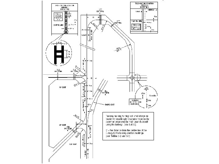
Runway-holding position marking • A runway-holding position marking shall be displayed along a runway-holding position. • At an intersection of a taxiway and a noninstrument, non-precision approach or take-off runway, the runway-holding position marking shall be as shown • Where two or three runway-holding positions are provided at such an intersection, the runwayholding position marking closer (closest) to the runway shall be as shown
Runway-holding position marking
Intermediate holding position marking • An intermediate holding position marking should be displayed along an intermediate holding position. • An intermediate holding position marking shall consist of a single broken line
Intermediate holding position marking
VOR aerodrome check-point marking • When a VOR aerodrome check-point is established, it shall be indicated by a VOR aerodrome check-point marking and sign. • A VOR aerodrome check-point marking shall be centred on the spot at which an aircraft is to be parked to receive the correct VOR signal. • A VOR aerodrome check-point marking shall consist of a circle 6 m in diameter and have a line width of 15 cm.
VOR aerodrome check-point marking
Apron Safety Lines • Apron safety lines should be provided on a paved apron as required by the parking configurations and ground facilities. • An apron safety line should be continuous in length and at least 10 cm in width. • An apron safety line shall not be coloured where an aicraft will cross the line
Apron Safety Lines
Information Marking • Where it is impracticable to install an information sign, the information should be conveyed through an information marking. • The marking shall be yellow. • The character height should be 4 m.
Information Marking