60 Mechanical Design Review Template Cognizant Engineers Title


![µ-metal Global shield Simulations Material Thickness [in] Magnetic field [m. Oe] Global single no µ-metal Global shield Simulations Material Thickness [in] Magnetic field [m. Oe] Global single no](https://slidetodoc.com/presentation_image_h2/417b19a1153831cd0fb8c70b2853ceb4/image-29.jpg)


![Local A 4 K Shield Simulations Material Thickness [in] Magnetic field [m. Oe] Local Local A 4 K Shield Simulations Material Thickness [in] Magnetic field [m. Oe] Local](https://slidetodoc.com/presentation_image_h2/417b19a1153831cd0fb8c70b2853ceb4/image-32.jpg)


- Slides: 47

60% Mechanical Design Review Template Cognizant Engineer’s Title

Outline § Overview § Requirements § Interfaces § Primary functions of the design § Evaluation of concepts that meet requirements § Engineering analysis presentation Example Agenda § Verification plan § Proposed production schedule § Summary A. Presenter, 7 Aug 2009, Slide 2

Overview § Requestor: § Start date: § Purposed completion date: § Any special conditions/constraints: collaboration with XXX, A. Presenter, 7 Aug 2009, Slide 3

Requirements § DCC document number: 1. Demands (Performance Requirements) of the design (items that are required to work otherwise the design does not function) 1. 2. Requires bayonets from Mfg: XXX pt no: XXX Designed to ASME pressure vessel code 2. Wishes of the design 1. 2. 3. 4. 5. Light Compact Easy of assembly Minimial number of parts Simplicity 3. Engineering analysis required: 1. 2. 3. 4. Pressure analysis Structural analysis Thermal analysis Lifting analysis A. Presenter, 7 Aug 2009, Slide 4

Interface Requirements § DCC document number: § Main interface constraints are: A. Presenter, 7 Aug 2009, Slide 5

Primary Functions of the Design § Primary functions of the design is explained. § See slide 16 for example. A. Presenter, 7 Aug 2009, Slide 6

Solutions Options that Meet Requirements § See slides 17 -46 A. Presenter, 7 Aug 2009, Slide 7

Evaluation of Designs § Show design alternatives § Evaluate alternatives that meet requirements in a QFD (see example slide 47) I: departmentsmechdesignuserfilemjohnsonQFD-Cryomodule Alignment. xlsx § The QFD is the most important item to show that you: • Have considered all solution options • Evaluated the solutions based on the requirements • Identified the best solution available in the open-ended solution domain. A. Presenter, 7 Aug 2009, Slide 8

Engineering Analysis § Presented by the assigned person from the analysis team A. Presenter, 7 Aug 2009, Slide 9

Verification Plan § Explain demand requirements of the design will be verified with a test: A. Presenter, 7 Aug 2009, Slide 10

Summary § Requirements and interface documents approved in DCC § 3 D CAD completed and assembly drawing completed § Ready for detail drawings § Long lead items identified for purchased § Target completion date for checked drawings into DCC (2 weeks for checking and approval): § Review & Redline of printed assembly drawing A. Presenter, 7 Aug 2009, Slide 11

MAGNETIC SHIELDING OPTIMIZATION Mark Shuptar Mechanical Engineer

Overview § Objective: This presentation reviews the optimization of the magnetic shielding for the Re. A 6 cryomodule. § Background: The resonators of the Re. A 6 cryomodule operate optimally with minimal outside magnetic influences. These influences are primarily the result of earth’s magnetic field, any field residing on permeable components. During operation cavity performance could be limited if the magnetic field generated by the solenoid is too great. § The following slides will give an overview of the requirements, design process and evaluation of different concepts in the solution domain. § The production specifications are evaluated against the product requirements in a quality functional deployment (QFD) matrix to numerically illustrate the best design option M. SHUPTAR, 28 JULY 2012, Slide 13

Design Process from Requirements to Specifications § Requirements: are obtained made at the design kick off meeting and come in two forms: • Demands – the requirement must be accomplished from the design. Example: Residual magnetic field in the resonators during operation needs to be < 15 m. Oe • Wish's – requirements is comprisable and weighed so design can be optimized. » Example: Minimize the number of parts required for assembly. § Functions: lead engineer defines solution neutral problem statements. • Shield resonators from external magnetic fields imposed by all outside components until < Tc § Specifications: are detailed metrics of what the design will do and made by lead engineer. These are the final drawings, manufacturers and part numbers of the product to be delivered to the CAMs. • Example: Shield constructed of. 062” thick Mu-Metal by Amuneal Corp. • Example: Detail drawing package T 12345 -MDE-000 X-0000 M. SHUPTAR, 28 JULY 2012, Slide 14

Design and Derived Requirements Performance Requirements: R. 1 Residual magnetic field in the Resonators < 15 m. Oe Mechanical Requirements: R. 2 R. 3 R. 4 R. 5 R. 6 R. 7 Interface with the Vacuum Vessel Interface with Coldmass Interface with Cryogenics Occupy space between thermal shield and Vacuum Vessel Allow post-assembly access to FPC Compliant with bottom up design Demand requirements are tracked and require a verification plan to show design meets them. Safety R. 8 User R. 9 Lifting/Transportation R. 10 Operation Design Wishes Low Cost Ease of Assembly Minimize number of components Minimize onsite welding Design wishes are evaluated by analysis or in 60% Design Review M. SHUPTAR, 28 JULY 2012, Slide 15

Function: Operating Procedure When the resonators fall below Tc the magnetic field no longer penetrates inside allowing larger fields to be present. This is important during operation of the solenoid where stray fields will certainly be > 15 m. Oe M. SHUPTAR, 28 JULY 2012, Slide 16

Design Approaches § Based on the requirements and functionality, there are two major design approaches that currently exist: 1. Use a room temperature global shield that encases the all 8 resonators inside a single shield 2. Use cold local shields that encase each the resonators § Hybrids of these designs are also under consideration • Use a global shield in parallel with a local shield: use #1 and #2 • Adjust the number of resonators encased of option #2 M. SHUPTAR, 28 JULY 2012, Slide 17

3 D Models Design approach #1 Room temperature global shield Design approach #2 Local cold shield around end resonator Local Cold Shield (Multiresonator area) M. SHUPTAR, 28 JULY 2012, Slide 18

Cost Breakdown § A cost analysis was completed • based on a cost/sheet quote provided by a vendor. • Accounted for all available thicknesses offered • # Sheets account for ~10% scrap Approach #1 Mu-Metal Approach #2 -1 A 4 K Single Cavity Approach #2 -2 A 4 K Multi-Cavity Thickness. 02". 04". 062". 125". 02". 04". 062" Sheet Size 24" X 120" 24" X 120" 24" X 78" 24" X 120" Cost/sheet Sheets needed Cost $871. 86 24 $20, 924. 64 $1, 729. 16 24 $41, 499. 84 $2, 680. 18 24 $64, 324. 32 $7, 646. 00 24 $183, 504. 00 $1, 155. 80 16 $18, 492. 80 $1, 440. 50 24 $34, 572. 00 $3, 079. 68 16 $49, 274. 88 $1, 155. 80 14 $16, 181. 20 $1, 440. 50 22 $31, 691. 00 $3, 079. 68 14 $43, 115. 52 M. SHUPTAR, 28 JULY 2012, Slide 19

DESIGN OPTIONS § Since vendors provide a wide variety of thicknesses; analysis had to be done to get an initial evaluation of effectiveness. § After running some initial FEA studies (presented here today by Y. Xu), the number of viable designs were refined down to 4 design alternatives based on fulfilling the demanded requirements: • Use a 1/8” m-Metal global shield • Use. 04” A 4 K around each cavity with no global shield » Single Cavity Design » Multi-Cavity Design • Use. 04” A 4 K around each cavity with. 062” global shield • Use 2 X. 062” m-Metal global shield M. SHUPTAR, 28 JULY 2012, Slide 20

Option #1: a 1/8” m-Metal Shield § Pros: • Simply to assemble • Compliant with space restrictions between the Thermal Shield and Vacuum Vessel • Attenuates the effects of Earth’s magnetic field on the cavities. § Cons: • Does not protect the cavities from the solenoid’s magnetic field: » Cavity is not protected from the solenoid in the event of a cavity quench » Solenoid might have to be degaussed if a cavity ever quenched. • Large sections need to be removed in order to service cryomodule § Cost: $183, 504. 00 M. SHUPTAR, 28 JULY 2012, Slide 21

Option #2: . 04” A 4 K (Single Cavity) § Pros: • Assembly is easier to manage because it is smaller • Assembly allows for easy access to FPC and other cryomodule components • Protects cavity from earths magnetic field and solenoid. § Cons: • Has to be cooled before it reaches optimal effectiveness. • Further analysis needs to be done to validate that it can hit the requirement of minimizing the magnetic field to under 15 m. Oe. • Extra shielding is required between resonators to be effective § Cost: $34, 572. 00 M. SHUPTAR, 28 JULY 2012, Slide 22

Option #3: . 04” A 4 K Shield (Multi-Cavity) § Pros: • Still a relatively simple assembly • 4 assemblies as opposed to 8 assemblies for single cavity • Assembly allows for easy access to FPC and other cryomodule components • Protects cavity from earths magnetic field and solenoid. § Cons: • Has to be cooled before it reaches optimal effectiveness. • Further analysis needs to be done to validate that it can hit the requirement of minimizing the magnetic field to under 15 m. Oe. • Multi-Cavity shield will need to span across 2 rail sections § Cost: $31, 691. 00 M. SHUPTAR, 28 JULY 2012, Slide 23

Option #4: . 04” A 4 K +. 062” m-Metal Shield § Pros: • Compliant with space restrictions between the Thermal Shield and Vacuum Vessel • One shield attenuates Earth’s magnetic shield while another shield attenuates the solenoid’s magnetic field. § Cons: • Redundancy of systems may not be necessary. • Added complexity of 2 shields • Large sections need to be removed in order to service cryodmodule • Analysis would still need to be done to validate design. § Cost: $31, 691. 00 (A 4 K Multi-Cavity)+$64, 234. 32 (m-Metal Shield)= $95, 925. 32 M. SHUPTAR, 28 JULY 2012, Slide 24

Finally Option #5: 2 X. 062” m-Metal Shields § Pros: • Attenuates Earth’s magnetic field. § Cons: • More effective as distance between shields increases, current space restrictions only allow for. 1” gap • Added complexity of 2 shields • Does not protect the cavities from the solenoid’s magnetic field: » Cavity is not protected from the solenoid in the event of a cavity quench » Solenoid might have be degaussed if a cavity ever quenched. • Complex support structure to facilitate 2 layers of shielding § Cost: $128, 648. 64 M. SHUPTAR, 28 JULY 2012, Slide 25

Re. A 6 Magnetic Shield Analysis Ying Xu Mechanical Design Engineer

Shield Design Options Concept #1, room temp global shielding Concept #2, cryogenic local shielding • Both shielding options require < 15 m. Oe when resonator makes superconducting transition ~9 K. • Once resonator is superconducting magnetic field can be > 15 m. Oe Ying Xu, 28 Aug 2012 , Slide 27

Boundary Conditions § Global Shielding • µ-metal shield @ room temperature • Permeability: 60000 • Earth field 0. 5 Gauss • Earth field parallel to ground Global shield § Local shielding • A 4 K shield @ 40 K • Permeability: 65000 • Earth field 0. 5 Gauss • Earth field parallel to ground Individual shields Ying Xu, 28 Aug 2012, Slide 28
![µmetal Global shield Simulations Material Thickness in Magnetic field m Oe Global single no µ-metal Global shield Simulations Material Thickness [in] Magnetic field [m. Oe] Global single no](https://slidetodoc.com/presentation_image_h2/417b19a1153831cd0fb8c70b2853ceb4/image-29.jpg)
µ-metal Global shield Simulations Material Thickness [in] Magnetic field [m. Oe] Global single no penetration holes µ-metal 0. 062 23. 6 Global thin double no penetration holes µ-metal 0. 04 x 2 17. 5 Global thin double no penetration holes µ-metal 0. 05 x 2 14. 9 Global double no penetration holes µ-metal 0. 062 x 2 12. 1 Global thick single no penetration holes µ-metal 0. 125 12. 2 Global thick single penetration holes µ-metal 0. 125 14. 1 Penetration holes for tuner, FPC, support posts, cryogenics piping Bottom view Requirement [m. Oe] <15 1 global shield that encompasses entirety of cold mass , Slide 29 Ying Xu, 28 Aug 2012

Global Shield Magnetic Field , Slide 30 Ying Xu, 28 Aug 2012

Global Shield Cavity Magnetic Field , Slide 31 Ying Xu, 28 Aug 2012
![Local A 4 K Shield Simulations Material Thickness in Magnetic field m Oe Local Local A 4 K Shield Simulations Material Thickness [in] Magnetic field [m. Oe] Local](https://slidetodoc.com/presentation_image_h2/417b19a1153831cd0fb8c70b2853ceb4/image-32.jpg)
Local A 4 K Shield Simulations Material Thickness [in] Magnetic field [m. Oe] Local 1 -cavity no penetration holes A 4 K 0. 02 30. 1 Local 1 -cavity no penetration holes A 4 K 0. 04 14. 6 Local 1 -cavity penetration holes A 4 K 0. 04 38. 1 Local 1 -cavity penetration holes w/ hat A 4 K 0. 04 11. 2 Local 8 -cavity penetration holes A 4 K 0. 04 77. 9 Local 8 -cavity penetration holes w/ hat A 4 K 0. 04 40. 5 Local 8 -cavity penetration holes w/ hat rail slot A 4 K 0. 04 45. 3 Local 8 -cavity penetration holes w/ hat rail slot No side rail slot A 4 K 0. 04 19. 6 Local multi-cavity penetration holes w/ hat A 4 K 0. 04 9. 5 Local multi-cavity penetration holes w/ hat rail slot A 4 K 0. 04 39. 8 Local multi-cavity penetration holes w/ hat rail slot No side rail slot A 4 K 0. 04 13. 1 Requirement [m. Oe] <15 , Slide 32 Ying Xu, 28 Aug 2012

Local Single-Cavity A 4 K Shield , Slide 33 Ying Xu, 28 Aug 2012

Local Single-Cavity A 4 K Shield ─ Shield Magnetic Field , Slide 34 Ying Xu, 28 Aug 2012

Local Single-Cavity A 4 K Shield ─ Cavity Magnetic Field , Slide 35 Ying Xu, 28 Aug 2012

Local Single-Cavity A 4 K Shield No Side Rail No side rail , Slide 36 Ying Xu, 28 Aug 2012

Local Single-Cavity A 4 K Shield No Side Rail ─ Shield Magnetic Field , Slide 37 Ying Xu, 28 Aug 2012

Local Single-Cavity A 4 K Shield No Side Rail ─ Cavity Magnetic Field , Slide 38 Ying Xu, 28 Aug 2012

Local Multi-Cavity A 4 K Shield , Slide 39 Ying Xu, 28 Aug 2012

Local Multi-Cavity A 4 K Shield ─ Shield Magnetic Field , Slide 40 Ying Xu, 28 Aug 2012

Local Multi-Cavity A 4 K Shield ─ Cavity Magnetic Flux , Slide 41 Ying Xu, 28 Aug 2012

Local Multi-Cavity A 4 K Shield No Side Rail No side rail , Slide 42 Ying Xu, 28 Aug 2012

Local Multi-Cavity A 4 K Shield No Side Rail ─ Shield Magnetic Field , Slide 43 Ying Xu, 28 Aug 2012

Local Multi-Cavity A 4 K Shield No Side Rail ─ Cavity Magnetic Field , Slide 44 Ying Xu, 28 Aug 2012

Summary Designs meet the requirement Double 0. 062” µ-metal global shield Singe 0. 125” µ-metal global shield Local multi-cavity A 4 K shield Side rail move outward , Slide 45 Ying Xu, 28 Aug 2012

Cost Summary Design Option Material Cost Fabrication Assembly Total Cost 1/8” Mu-Metal Shield $183, 504. 00 $16, 000. 00 $1, 800. 00 $201, 304. 00. 04” A 4 K (Single Cavity) $34, 572. 00 $8, 000. 00 $2, 400. 00 $44, 972. 00. 04” A 4 K Shield (Multi-Cavity) $31, 691. 00 $8, 000. 00 $1, 350. 00 $41, 041. 00. 04” A 4 K +. 062” Mu-Metal Shield $95, 925. 32 $24, 000. 00 $4, 200. 00 $124, 125. 32 2 X. 062” Mu-Metal Shields $128, 648. 64 $32, 000. 00 $3, 600. 00 $164, 248. 64 M. SHUPTAR, 28 JULY 2012, Slide 46

14. 1 10. 0 2 9 12. 7 9. 0 Minimal Complexity 2 9 11. 3 8. 0 Cost 3 9 11. 3 8. 0 Number of Parts 4 9 12. 7 9. 0 Compatible with bottom up Design 5 9 12. 7 9. 0 6 9 12. 7 7 9 12. 7 ▲ Θ Θ Ο Ο Ο Θ Θ Multi-Cavity A 4 K Shield Ο Ο Θ Θ Thin Mu-Metal global shield + Cavity Cryo-perm shield Inducted field is less than 15 m. Oe at cavity surface 1 3 Single Cavity A 4 K Shield Demanded Quality (a. k. a. "Customer Requirements" or "Whats") Thick Mu-Metal global shield Weight / Importance Quality Characteristics (a. k. a. "Functional Requirements" or "Hows") 2 x. 062" thich Mu-Metal shields § Conclusion: Local cryoperm or A 4 K shielding is the best design choice, specifically using a Multi-Cavity shield configuration. Relative Weight § Quality function deployment (QFD) is a “method to transform user demands into design quality, to deploy the functions forming quality, and to deploy methods for achieving the design quality into subsystems and component parts, and ultimately to specific elements of the manufacturing process. ”, [1] as described by Dr. Yoji Akao, who originally developed QFD in Japan in 1966, when the author combined his work in quality assurance and quality control points with function deployment used in value engineering. Max Relationship Value in Row Quality Function Deployment ▲ ▲ Ο Ο Ο ▲ Ο Ο Θ Ο Accomodates coldmass including FPC & tuner drive penetrations Maintain 1" spacing to the Thermal 9. 0 Shield and 1" Spacing to Vacuum Vessel Allow for post-assembly access to 9. 0 FPC Target or Limit Value Difficulty (0=Easy to Accomplish, 10=Extremely 2 3 3 8 5 Difficult) Max Relationship Value in Column 9 9 9 3 9 Weight / Importance 469. 0 671. 8 739. 4 150. 7 350. 7 Relative Weight 19. 7 28. 228 JULY 31. 0 2012, 6. 3 Slide 14. 7 47 M. SHUPTAR, Ο Θ Θ ▲ Ο
 Dmaic academy cognizant
 Lca payout cognizant
 Cognizant sitecore
 American society of mechanical engineers
 Mathcad mechanical engineering library
 Preliminary design review template
 Conceptual design review template
 Critical design review
 Actual mechanical advantage vs ideal mechanical advantage
 Prefatory part of report
 Title title
 Jeopardy title card
 Breadcrumb wireframe
 Book review grade 3
 Review title examples
 Sejarah microsoft publisher berawal dari tahun
 Exam review template
 Quarterly business review presentation
 Production readiness review template
 Architecture review board charter template
 Mita business process model
 Annual product review template
 Drug utilization evaluation template
 Sales opportunity review template
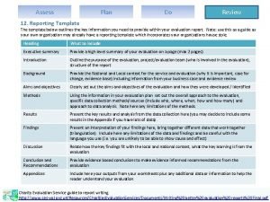
 Plan do review template
 Tollgate review template
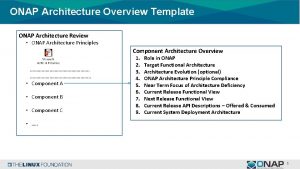
 Architecture review template
 Book report presentation template
 Tollgate review template
 Periodic service review
 Chapter review motion part a vocabulary review answer key
 Uncontrollable spending ap gov
 Nader amin-salehi
 Traditional and systematic review venn diagram
 Narrative review vs systematic review
 цомчн
цомчн Importance of machine design
 Hydraulic baffled wall flocculator
 Mechanical engineering design book
 Mechanical design of transmission line
 Machine elements in mechanical design 5th edition
 Balance in floral design
 Mechanical housing design
 Mechanical design and fabrication
 Cold box design
 Mechanical design of process equipment
 Machine elements in mechanical design
 Mechanical

