UNIT III REGISTER TRANSFER LANGUAGE AND DESIGN OF



- Slides: 46
UNIT III REGISTER TRANSFER LANGUAGE AND DESIGN OF CONTROL UNIT
Con………. . • The internal hardware organization of a digital computer is best defined by specifying: 1. The set of registers it contains and their function. 2. The sequence of micro operations performed on the binary information stored in the registers. 3. The control that initiates the sequence of micro operations.
Con…… • Register: In a computer, a register is one of a small set of data holding places that are part of a computer processor. A register may hold a computer instruction, a storage address, or any kind of data. • The operations executed on data stored in register & are called micro operations. • A micro oper ationis an elementary operation performed on the information stored in one or more registers. • The result of the operation may replace the previous binary information of a register or may be transferred to another register.
Con…. • The symbolic notation used to describe the micro operation transfers among registers is called a register transfer language. • The term "register transfer" implies the availability of hardware logic circuits that can perform a stated micro operation and transfer the result of the operation to the same or another register. • A programming language is a procedure for writing symbols to specify a given computational process. • A register transfer language is a system for expressing in symbolic form the micro operation sequences among the registers of a digital module.
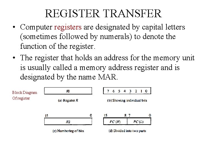
REGISTER TRANSFER • Computer registers are designated by capital letters (sometimes followed by numerals) to denote the function of the register. • The register that holds an address for the memory unit is usually called a memory address register and is designated by the name MAR. Block Diagram Of register
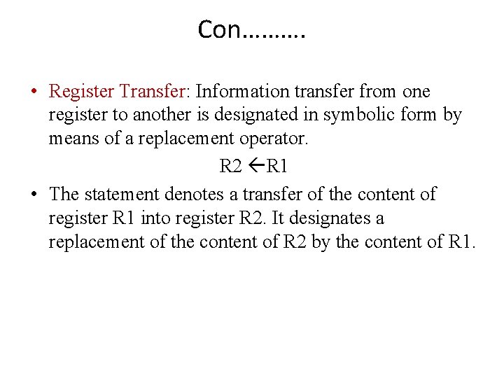
Con………. • Register Transfer: Information transfer from one register to another is designated in symbolic form by means of a replacement operator. R 2 R 1 • The statement denotes a transfer of the content of register R 1 into register R 2. It designates a replacement of the content of R 2 by the content of R 1.
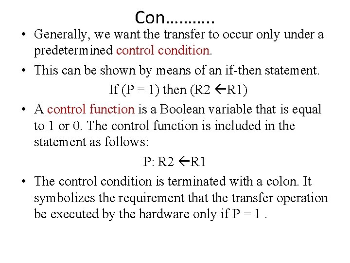
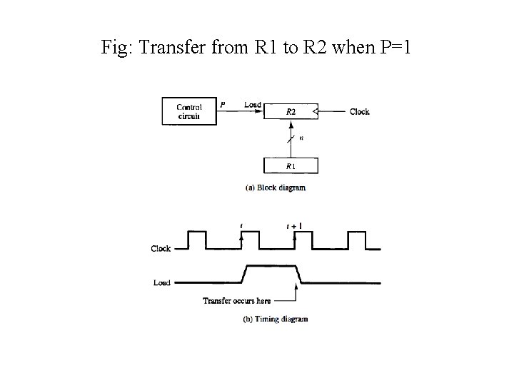
Con………. . • Generally, we want the transfer to occur only under a predetermined control condition. • This can be shown by means of an if then statement. If (P = 1) then (R 2 R 1) • A control function is a Boolean variable that is equal to 1 or 0. The control function is included in the statement as follows: P: R 2 R 1 • The control condition is terminated with a colon. It symbolizes the requirement that the transfer operation be executed by the hardware only if P = 1.
Fig: Transfer from R 1 to R 2 when P=1
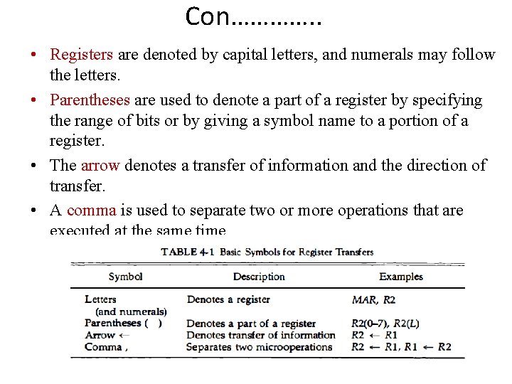
Con…………. . • Registers are denoted by capital letters, and numerals may follow the letters. • Parentheses are used to denote a part of a register by specifying the range of bits or by giving a symbol name to a portion of a register. • The arrow denotes a transfer of information and the direction of transfer. • A comma is used to separate two or more operations that are executed at the same time.
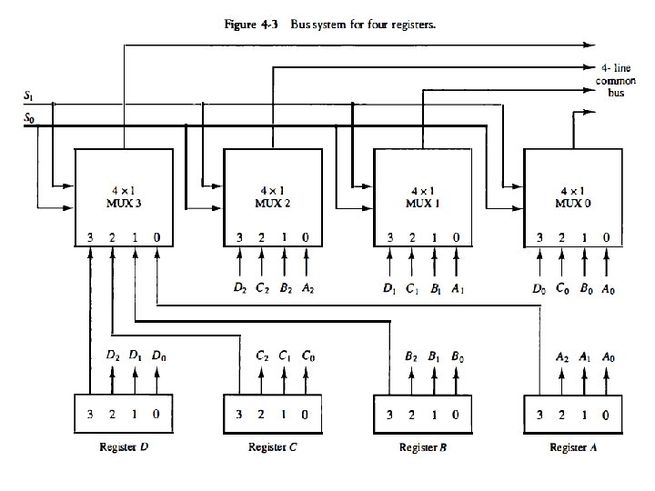
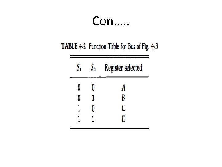
Bus and Memory Transfers • Transferring of information between registers in a multiple register configuration is a common bus system. • A bus structure consists of a set of common lines, one for each bit of a register, through which binary information is transferred one at a time.
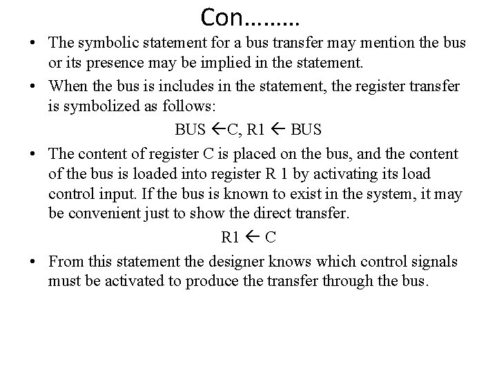
Con……… • The symbolic statement for a bus transfer may mention the bus or its presence may be implied in the statement. • When the bus is includes in the statement, the register transfer is symbolized as follows: BUS C, R 1 BUS • The content of register C is placed on the bus, and the content of the bus is loaded into register R 1 by activating its load control input. If the bus is known to exist in the system, it may be convenient just to show the direct transfer. R 1 C • From this statement the designer knows which control signals must be activated to produce the transfer through the bus.
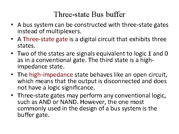
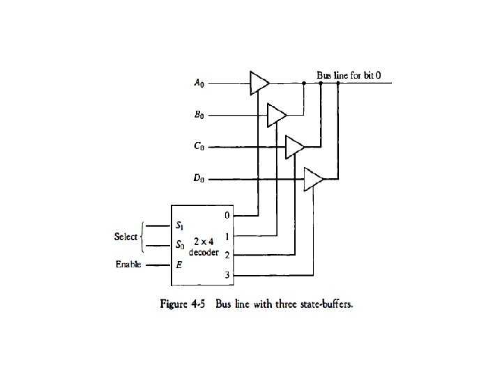
Three state Bus buffer • A bus system can be constructed with three-state gates instead of multiplexers. • A Three-state gate is a digital circuit that exhibits three states. • Two of the states are signals equivalent to logic 1 and 0 as in a conventional gate. The third state is a highimpedance state. • The high-impedance state behaves like an open circuit, which means that the output is disconnected and does not have a logic significance. • Three-state gates may perform any conventional logic, such as AND or NAND. However, the one most commonly used in the design of a bus system is the buffer gate.
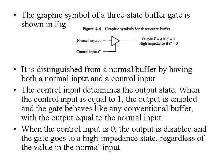
• The graphic symbol of a three state buffer gate is shown in Fig. • It is distinguished from a normal buffer by having both a normal input and a control input. • The control input determines the output state. When the control input is equal to 1, the output is enabled and the gate behaves like any conventional buffer, with the output equal to the normal input. • When the control input is 0, the output is disabled and the gate goes to a high impedance state, regardless of the value in the normal input.
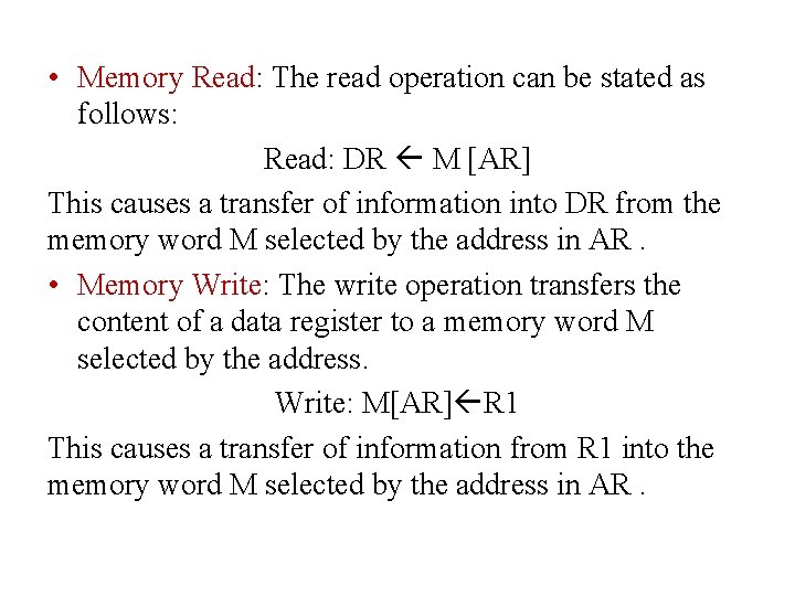
Memory transfer • The transfer of information from a memory word to the outside environment is called a read operation. • The transfer of new information to be stored into the memory is called a write operation. • A memory word will be symbolized by the letter M. • A memory unit that receives the address from a register, called the address register, symbolized by AR. • The data are transferred to another register, called the data register, symbolized by DR.
• Memory Read: The read operation can be stated as follows: Read: DR M [AR] This causes a transfer of information into DR from the memory word M selected by the address in AR. • Memory Write: The write operation transfers the content of a data register to a memory word M selected by the address. Write: M[AR] R 1 This causes a transfer of information from R 1 into the memory word M selected by the address in AR.
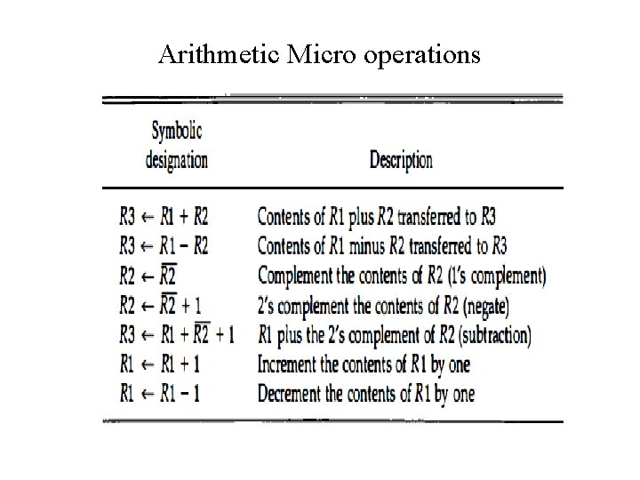
Arithmetic Micro operations
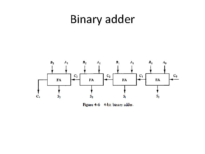
Binary adder
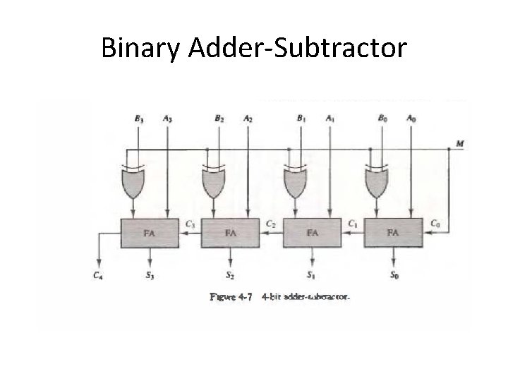
Binary Adder-Subtractor
Binary Incrementor
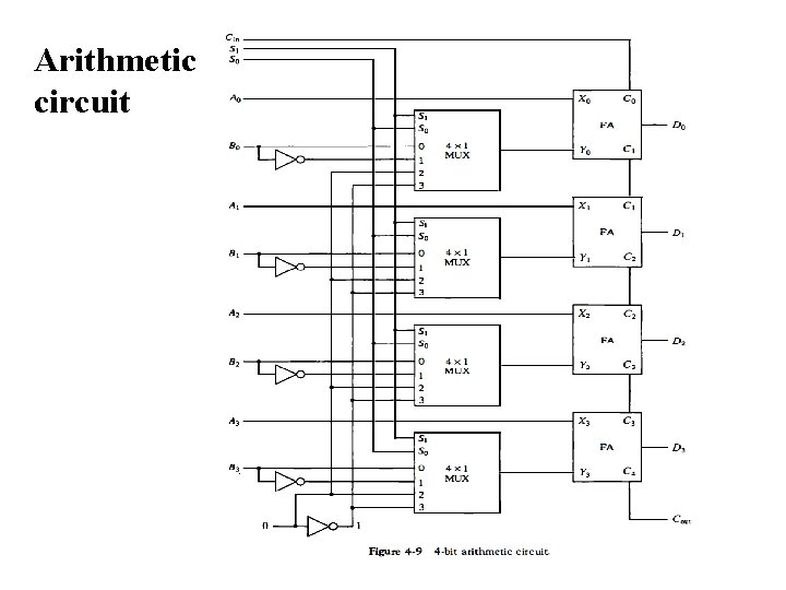
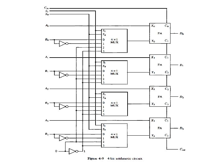
Arithmetic circuit
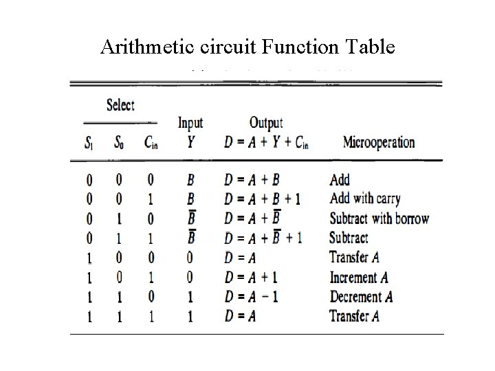
Arithmetic circuit Function Table
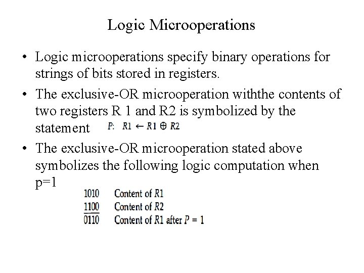
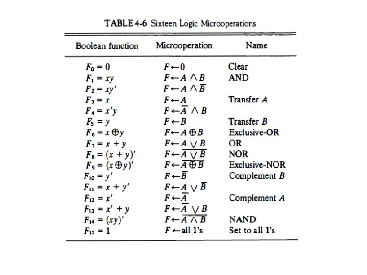
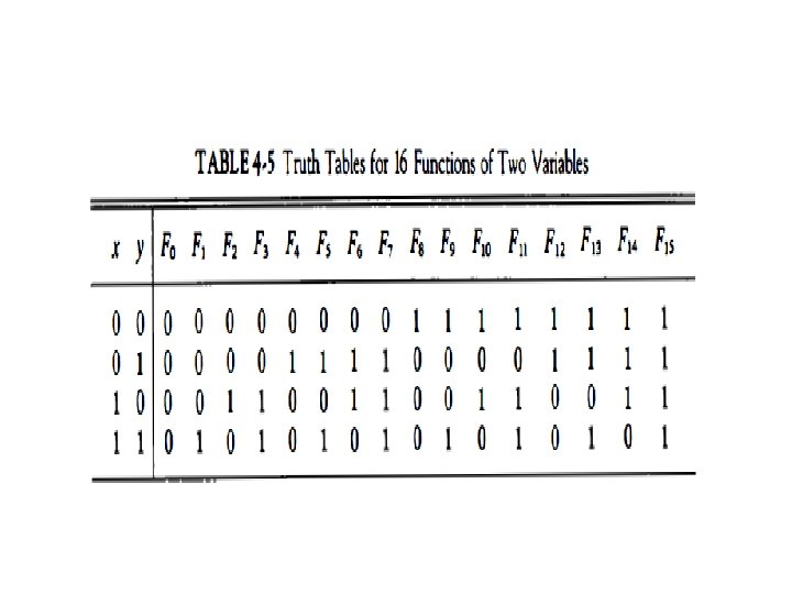
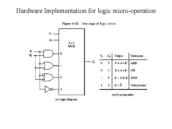
Logic Microoperations • Logic microoperations specify binary operations for strings of bits stored in registers. • The exclusive OR microoperation withthe contents of two registers R 1 and R 2 is symbolized by the statement • The exclusive OR microoperation stated above symbolizes the following logic computation when p=1
Hardware Implementation for logic micro operation
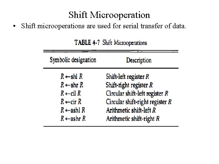
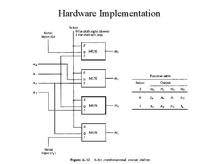
Shift Microoperation • Shift microoperations are used for serial transfer of data.
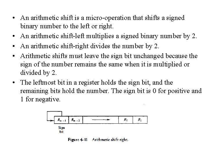
• An arithmetic shift is a micro operation that shifts a signed binary number to the left or right. • An arithmetic shift left multiplies a signed binary number by 2. • An arithmetic shift right divides the number by 2. • Arithmetic shifts must leave the sign bit unchanged because the sign of the number remains the same when it is multiplied or divided by 2. • The leftmost bit in a register holds the sign bit, and the remaining bits hold the number. The sign bit is 0 for positive and 1 for negative.
Hardware Implementation
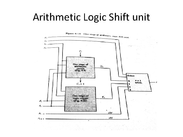
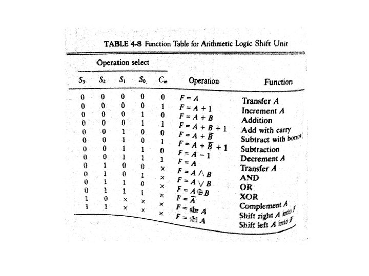
Arithmetic Logic Shift unit
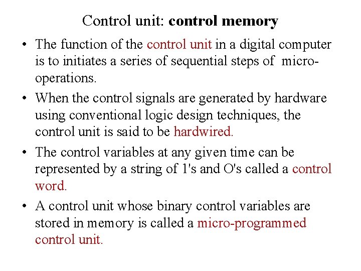
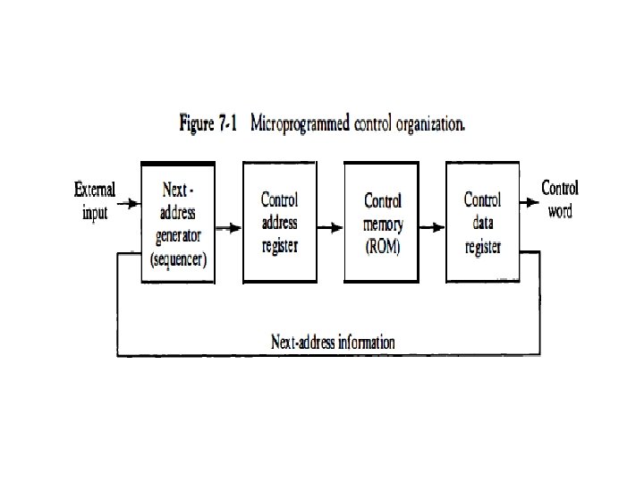
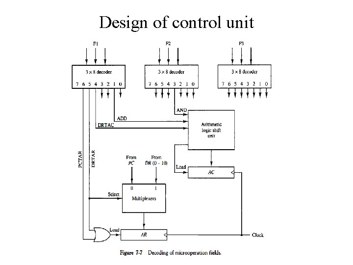
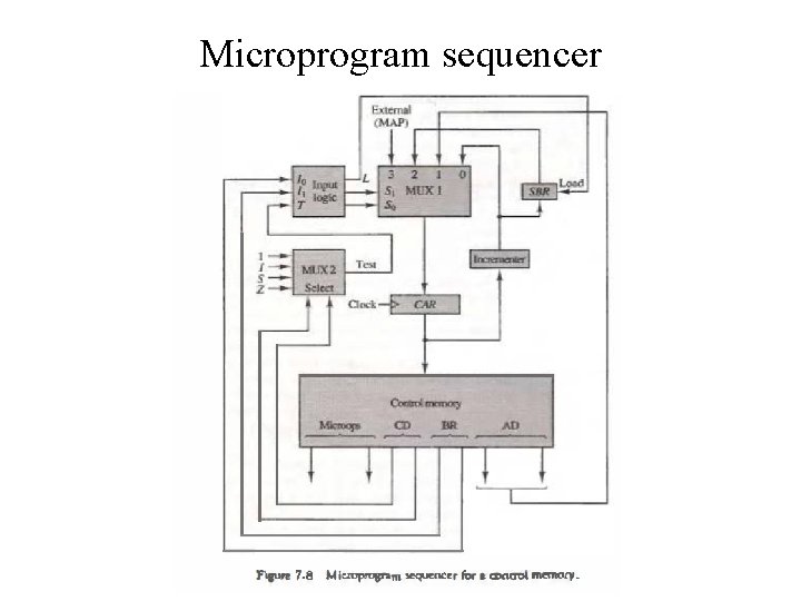
Control unit: control memory • The function of the control unit in a digital computer is to initiates a series of sequential steps of micro operations. • When the control signals are generated by hardware using conventional logic design techniques, the control unit is said to be hardwired. • The control variables at any given time can be represented by a string of 1's and O's called a control word. • A control unit whose binary control variables are stored in memory is called a micro programmed control unit.
Address sequencing
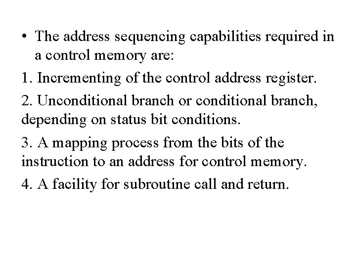
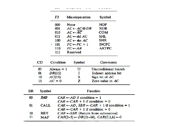
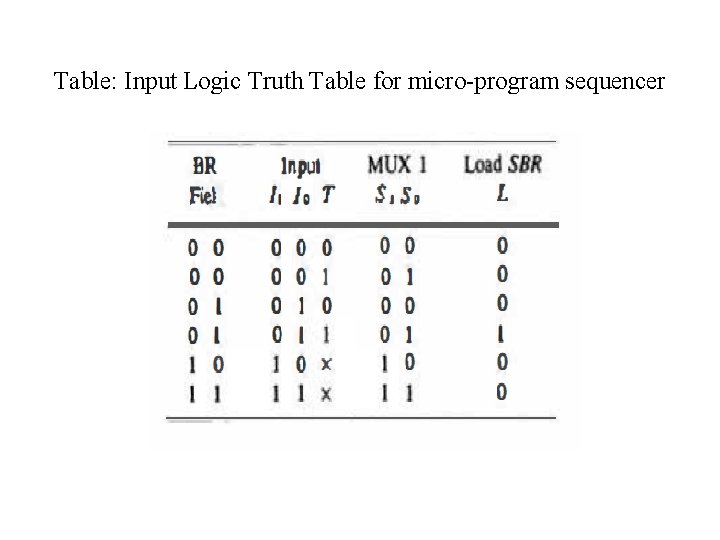
• The address sequencing capabilities required in a control memory are: 1. Incrementing of the control address register. 2. Unconditional branch or conditional branch, depending on status bit conditions. 3. A mapping process from the bits of the instruction to an address for control memory. 4. A facility for subroutine call and return.
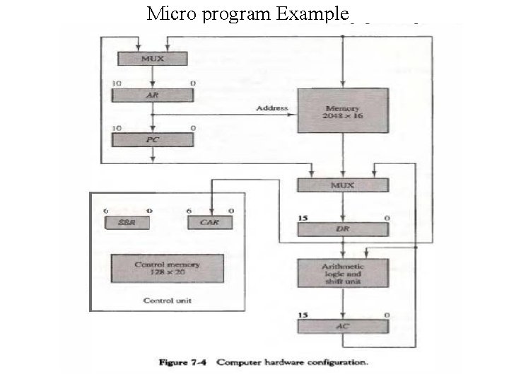
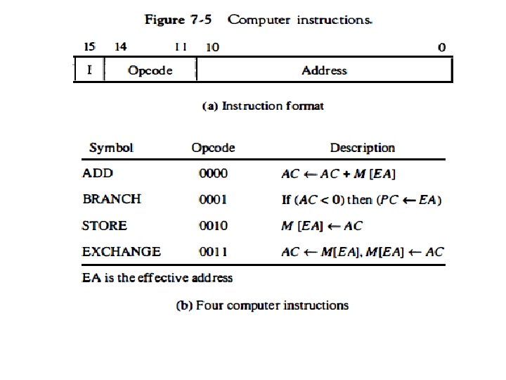
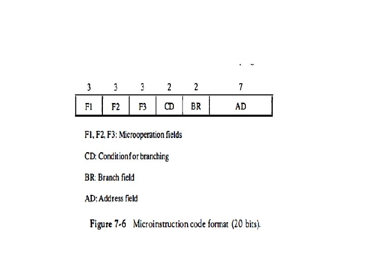
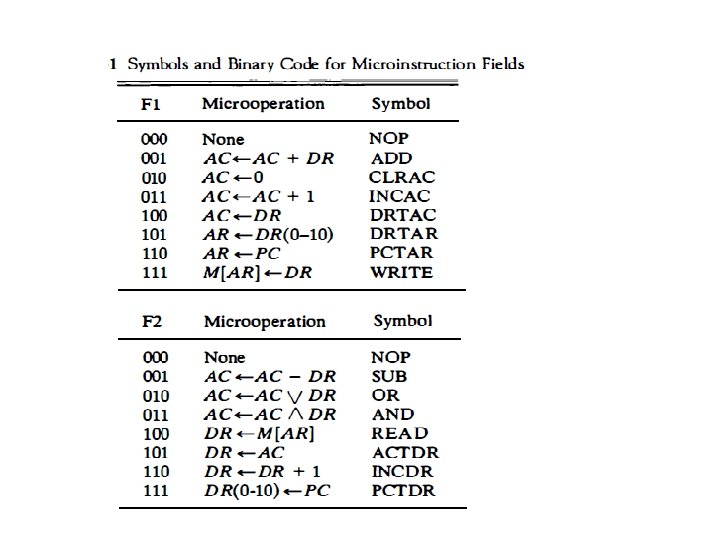
Micro program Example
Design of control unit
Microprogram sequencer
Table: Input Logic Truth Table for micro program sequencer