
Register file design review To write any register

- Slides: 6
Register file design review • To write any register, we need register address and a write signal • A 3 -bit write address is decoded if write signal is present • One of the eight registers gets a LD signal from decoder LD Data WA 3 to 8 D e c o d e r LD LD D 3 D 2 D 1 D 0 Q 3 Q 2 Q 1 Q 0 D 3 D 2 D 1 D 0 LD Q 3 Q 2 Q 1 Q 0 Clk D 3 D 2 D 1 D 0 Q 3 Q 2 Q 1 Q 0 Clk Reg LD Signal 7 6 5 4 3 2 1 0 RA 1 8 -to-1 4 -bit multiplex 7 6 5 4 3 2 1 0 8 -to-1 4 -bit multiplex RA 2 WR DATA 1 DATA 2 1
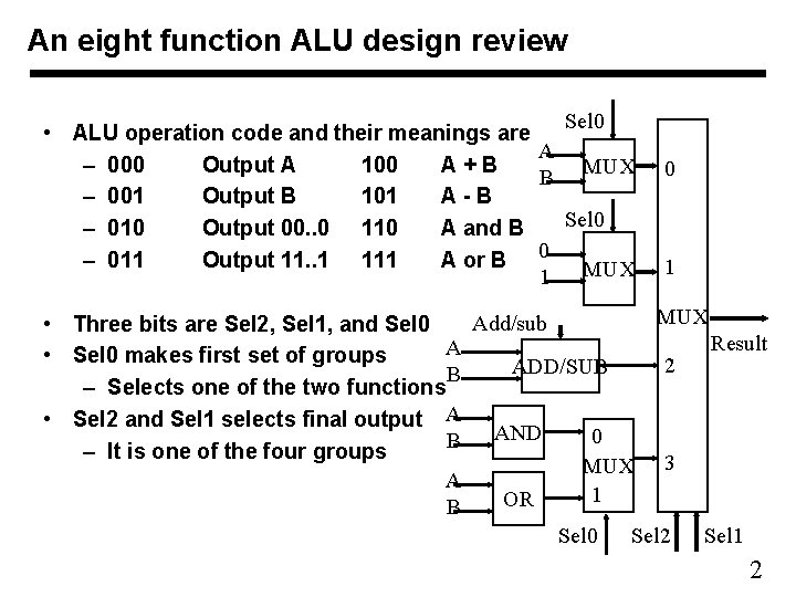
An eight function ALU design review Sel 0 • ALU operation code and their meanings are A – 000 Output A 100 A+B B MUX – 001 Output B 101 A-B Sel 0 – 010 Output 00. . 0 110 A and B – 011 Output 11. . 1 111 A or B 0 1 MUX Add/sub • Three bits are Sel 2, Sel 1, and Sel 0 Result A • Sel 0 makes first set of groups 2 ADD/SUB B – Selects one of the two functions • Sel 2 and Sel 1 selects final output A AND 0 B – It is one of the four groups MUX 3 A 1 OR B Sel 2 Sel 1 Sel 0 2
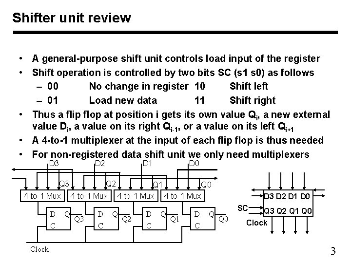
Shifter unit review • A general-purpose shift unit controls load input of the register • Shift operation is controlled by two bits SC (s 1 s 0) as follows – 00 No change in register 10 Shift left – 01 Load new data 11 Shift right • Thus a flip flop at position i gets its own value Qi, a new external value Di, a value on its right Qi-1, or a value on its left Qi+1 • A 4 -to-1 multiplexer at the input of each flip flop is thus needed • For non-registered data shift unit we only need multiplexers D 3 D 2 Q 3 4 -to-1 Mux D C Clock D 1 Q 2 4 -to-1 Mux Q Q 3 D C D 0 Q 1 Q 0 4 -to-1 Mux Q Q 2 D C Q Q 1 D C Q D 3 D 2 D 1 D 0 SC Q 0 Q 3 Q 2 Q 1 Q 0 Clock 3
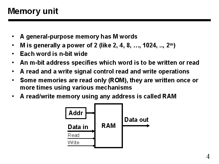
Memory unit • • • A general-purpose memory has M words M is generally a power of 2 (like 2, 4, 8, …, 1024, . . , 2 m) Each word is n-bit wide An m-bit address specifies which word is to be written or read A read and a write signal control read and write operations Some memories are read only (ROM), they are written once or more times using various mechanisms • A read/write memory using any address is called RAM Addr Data in RAM Data out Read Write 4
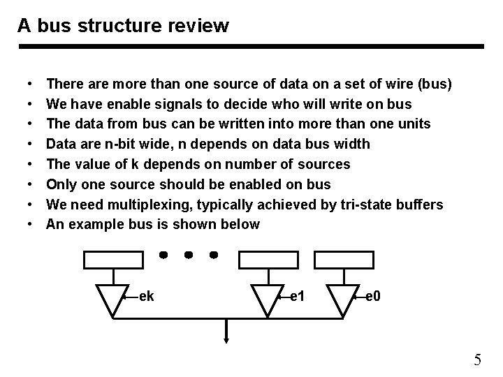
A bus structure review • • There are more than one source of data on a set of wire (bus) We have enable signals to decide who will write on bus The data from bus can be written into more than one units Data are n-bit wide, n depends on data bus width The value of k depends on number of sources Only one source should be enabled on bus We need multiplexing, typically achieved by tri-state buffers An example bus is shown below ek e 1 e 0 5
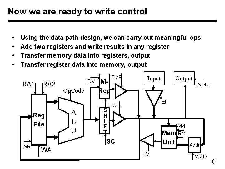
Now we are ready to write control • • Using the data path design, we can carry out meaningful ops Add two registers and write results in any register Transfer memory data into registers, output Transfer register data into memory, output RA 1 RA 2 Reg File WR LDM Op. Code A L U MReg S H I F T EMR Input WOUT EI EALU WM Mem RM SC WA Output Unit EM Addr WAD 6