Unit 1 Theory of Metal Cutting Metal Cutting











- Slides: 55
Unit 1 Theory of Metal Cutting
Metal Cutting • Metal cutting or traditional machining processes are also known as conventional machining processes. • These processes are commonly carried out in machine shops or tool room for machining a cylindrical or flat jobs to a desired shape, size and finish on a rough block of job material with the help of a wedge shaped tool. • The cutting tool is constrained to move relative to the job in such a way that a layer of metal is removed in the form of a chip.
Mechanism of chip formation
Mechanism of chip formation
Methods of cutting
Methods of cutting Orthogonal cutting is that type of cutting where the straight cutting edge of the wedge-shaped cutting tool is at right angle to the direction of cutting. The cutting edge is wider than the width of cut. The cutting edge does not pass the previously machined surface by this cutting edge so there is no influence of the previous cutting passes on the current pass. Oblique cutting is that type of cutting where the straight cutting edge of the wedge shaped cutting tool is not at right angle to the direction of cutting. The angle which the straight cutting edge makes with the direction of the cutting speed is known as the cutting edge inclination angle λs. The plastic deformation of the layer being removed in oblique cutting is more complicated than that in orthogonal cutting.
What is a Cutting Tool ? • A cutting tool is any tool that is used to remove metal from the work piece by means of shear deformation. • It is one of most important components in machining process • It must be made of a material harder than the material which is to be cut, and the tool must be able to withstand the heat generated in the metal cutting process. • Two basic types – Single point – Multiple point 7
Single Point Cutting Tool
Multi Point Cutting Tool
Inserts
Parts of Single point cutting tool
Parts of Single point cutting tool Shank: Main body of tool, it is part of which is gripped in tool holder Face: Top surface of tool b/w shank and point of tool. Chips flow along this surface Flank: Portion tool which faces the work. It is surface adjacent to & below the cutting edge when tool lies in a horizontal position. Point: Wedge shaped portion where face & flank of tool meet. Base: Bearing surface of tool on which it is held in a tool holder. Nose radius: Cutting tip, which carries a sharp cutting point. Nose provided with radius to enable greater strength, increase tool life & surface life. Typical Value : 0. 4 mm – 1. 6 mm
Geometry of Single point cutting tool
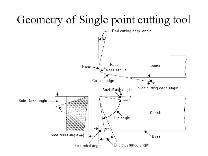
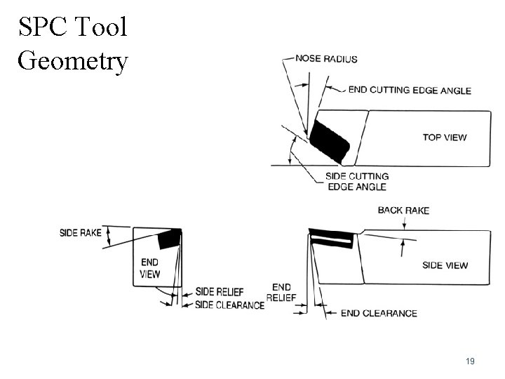
Geometry of Single point cutting tool Size- determined by the width of shank, height of shank and overall length. Shank- main body of a tool. It is held in a holder. Flank- the surface or surfaces below and adjacent to cutting edge. Heel- intersection of the flank and base of the tool. Base- the bottom part of the shank. It takes the tangential force of cutting. Face- surface of tool on which chip impinges when separated from workpiece. Cutting Edge- the edge of that face which separates chip from the workpiece. The total cutting edge consists of side cutting edge, the nose and end cutting edge. Tool Point- part which is shaped to produce the cutting edge and the face. The Nose- the intersection of side cutting edge and end cutting edge. Neck- the small cross section behind the point.
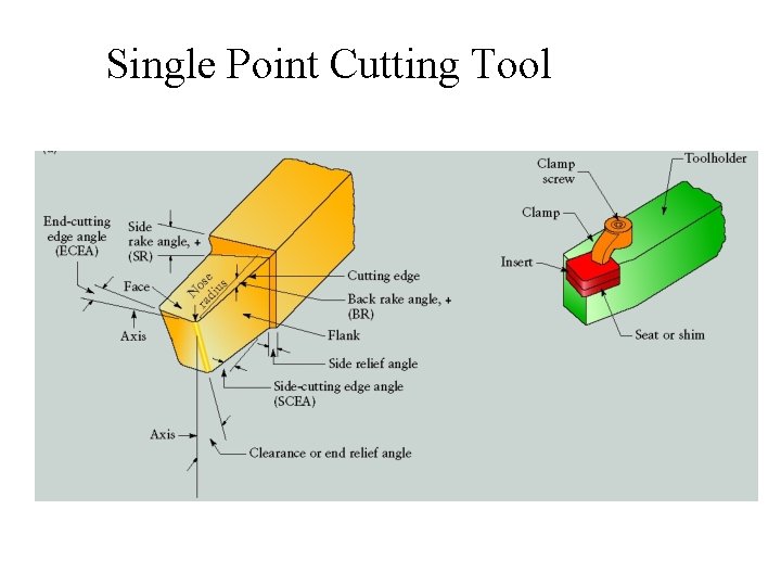
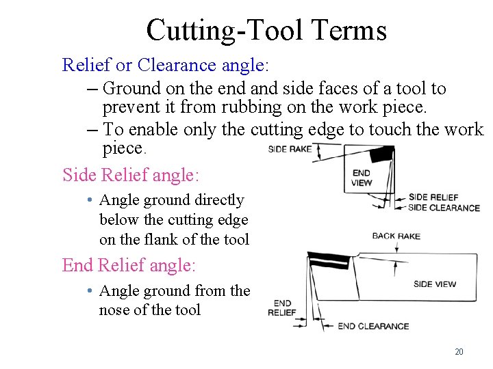
Geometry of Single point cutting tool Side Cutting Edge Angle • angle between side cutting edge and side of the tool shank, also called as lead angle or principle cutting angle. End Cutting Edge Angle • angle between the end cutting edge and a line perpendicular to the shank of tool Side Relief Angle • angle between the portion of the side flank immediately below the side cutting edge and line perpendicular to the base of tool measured at right angles to the side flank is known as side relief angle. • prevents interference, as the tool enters the work material. End Relief Angle • angle between the portion of the end flank immediately below the end cutting edge and the line perpendicular to the base of tool, measured at right angles to end flank. • allows the tool to cut without rubbing on the workpiece.
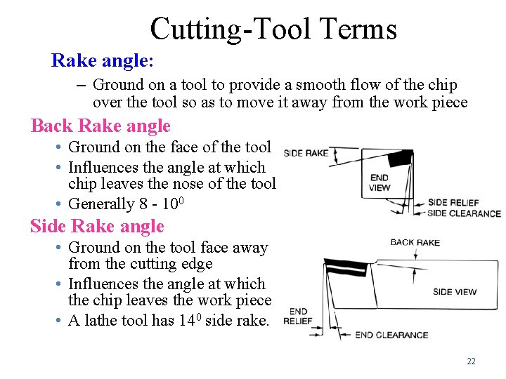
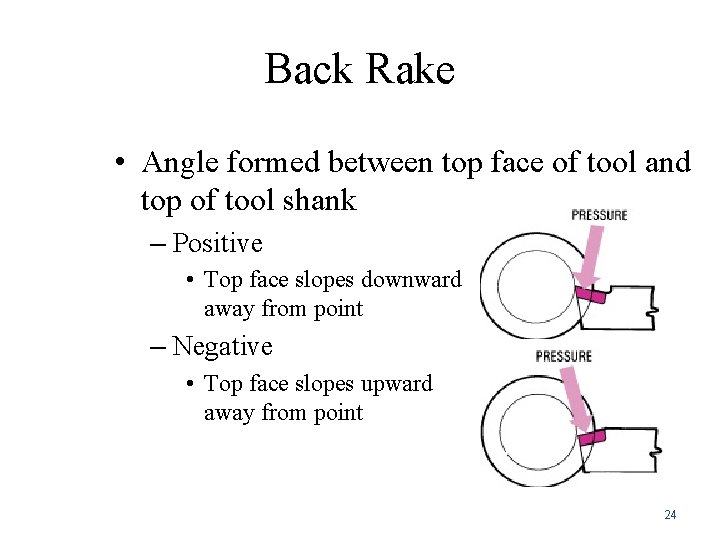
Geometry of Single point cutting tool Back Rake Angle • angle between face of the tool and a line parallel with the base of the tool, measured in a perpendicular plane through the side cutting edge. • It is the angle which measures the slope of the face of the tool from the nose toward the rear. • If the slope is downward toward the nose, it is negative back rake angle. • If the slope is downward from the nose, it is positive back rake angle. • If there is not any slope, back rake angle is zero. Side Rake Angle • angle between the face of the tool and a line parallel with the base of the tool, measured in a plane perpendicular to the base and side cutting edge. • It is the angle that measures the slope of the tool face from cutting edge. • If the slope is towards the cutting edge, it is negative side rake angle. • If the slope is away from the cutting edge, it is positive side rake angle.
Geometry of Single point cutting tool
Single Point Cutting Tool
SPC Tool Geometry 19
Cutting-Tool Terms Relief or Clearance angle: – Ground on the end and side faces of a tool to prevent it from rubbing on the work piece. – To enable only the cutting edge to touch the work piece. Side Relief angle: • Angle ground directly below the cutting edge on the flank of the tool End Relief angle: • Angle ground from the nose of the tool 20
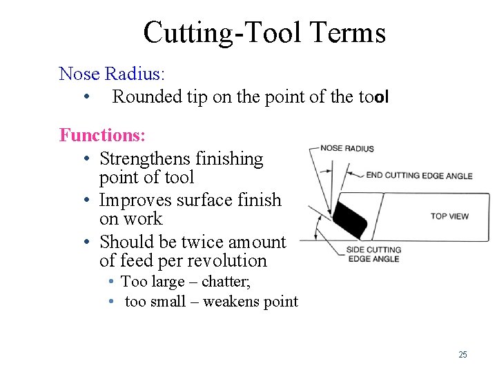
Cutting-Tool Terms Cutting edge angle • Ground on a tool so that it can be mounted in the correct position for various machining operations. Side Cutting edge angle • Allows flank of the tool to approach the work piece first • Spreads the material over a greater distance on the cutting edge, thereby thinning out the chip. • Approximately 150 End Cutting edge angle • Allows the cutting tool to machine close to the work piece during turning operations • Usually 20 – 300 21
Cutting-Tool Terms Rake angle: – Ground on a tool to provide a smooth flow of the chip over the tool so as to move it away from the work piece Back Rake angle • Ground on the face of the tool • Influences the angle at which chip leaves the nose of the tool • Generally 8 - 100 Side Rake angle • Ground on the tool face away from the cutting edge • Influences the angle at which the chip leaves the work piece • A lathe tool has 140 side rake. 22
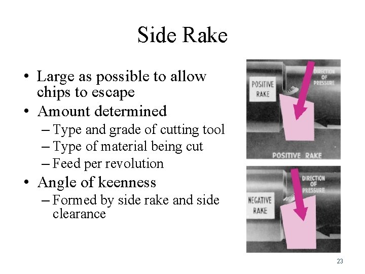
Side Rake • Large as possible to allow chips to escape • Amount determined – Type and grade of cutting tool – Type of material being cut – Feed per revolution • Angle of keenness – Formed by side rake and side clearance 23
Back Rake • Angle formed between top face of tool and top of tool shank – Positive • Top face slopes downward away from point – Negative • Top face slopes upward away from point 24
Cutting-Tool Terms Nose Radius: • Rounded tip on the point of the tool Functions: • Strengthens finishing point of tool • Improves surface finish on work • Should be twice amount of feed per revolution • Too large – chatter; • too small – weakens point 25
Tool signature • It is the system of designating the principal angles of a single point cutting tool. • The signature is the sequence of numbers listing the various angles, in degrees, and the size of the nose radius. • There are several systems available like American standard system (ASA), Orthogonal rake system (ORS), Normal rake system (NRS), and Maximum rake system (MRS). • The system most commonly used is American Standard Association (ASA), which is: Bake rake angle, Side rake angle, End relief angle, Side relief angle, End cutting Edge angle, Side cutting Edge angle and Nose radius.
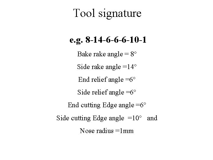
Tool signature e. g. 8 -14 -6 -6 -6 -10 -1 Bake rake angle = 8° Side rake angle =14° End relief angle =6° Side relief angle =6° End cutting Edge angle =6° Side cutting Edge angle =10° and Nose radius =1 mm
Types of Chips
Types of Chips
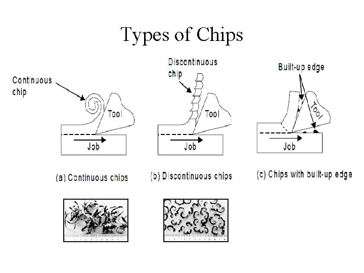
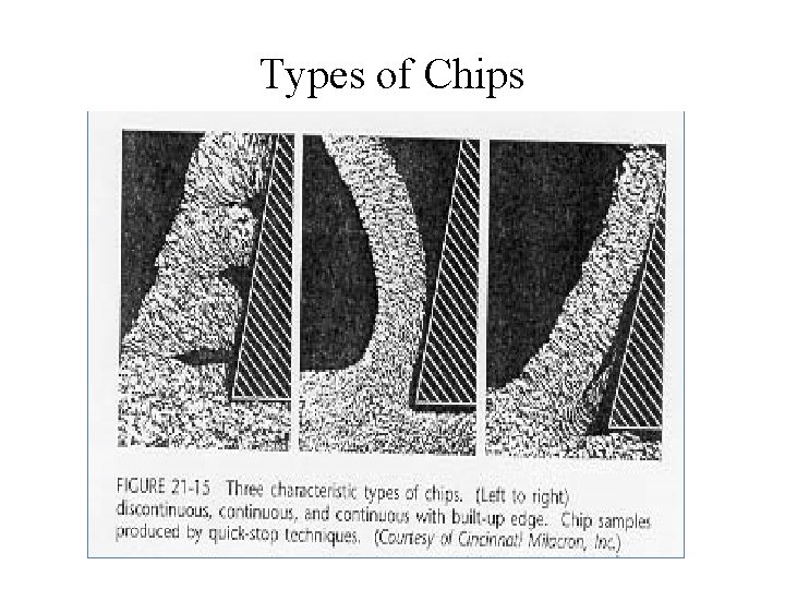
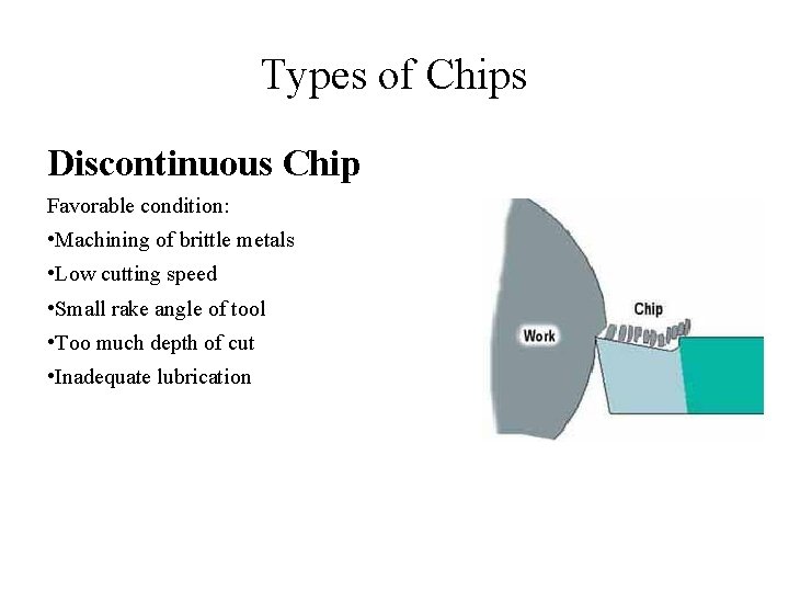
Types of Chips Discontinuous Chip Favorable condition: • Machining of brittle metals • Low cutting speed • Small rake angle of tool • Too much depth of cut • Inadequate lubrication
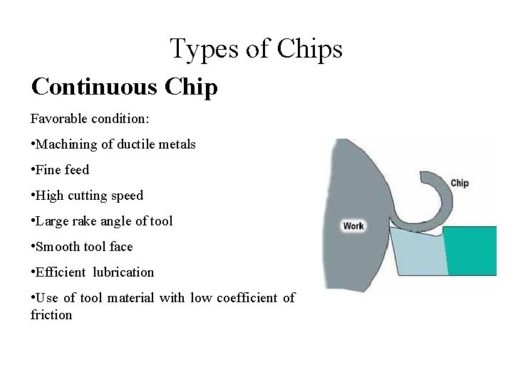
Types of Chips Continuous Chip Favorable condition: • Machining of ductile metals • Fine feed • High cutting speed • Large rake angle of tool • Smooth tool face • Efficient lubrication • Use of tool material with low coefficient of friction
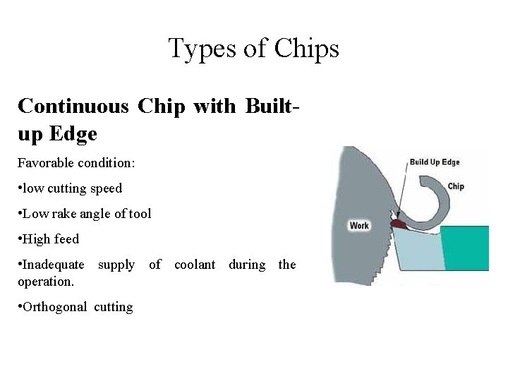
Types of Chips Continuous Chip with Builtup Edge Favorable condition: • low cutting speed • Low rake angle of tool • High feed • Inadequate supply of coolant during the operation. • Orthogonal cutting
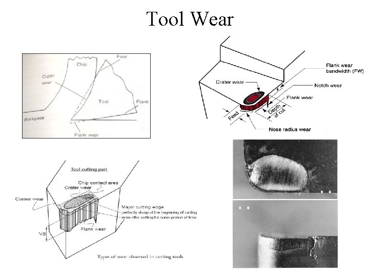
Tool Wear • • • The interaction between chip & tool and the work &tool. Cutting force Temperature developed during cutting process. Tool wear are classified by, 1. Flank wear 2. Creater wear on tool face 3. Chipping 4. Breakage 5. Loss of hardness due to the development of excessive temp.
Tool Wear
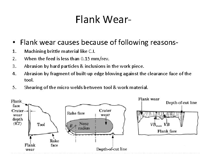
Flank Wear • Flank wear causes because of following reasons 1. 2. 3. 4. 5. Machining brittle material like C. I. When the feed is less than 0. 15 mm/rev. Abrasion by hard particles & inclusions in the work piece. Abrasion by fragment of built-up edge blowing against the clearance face of the tool. Shearing of the micro welds between tool & work material.
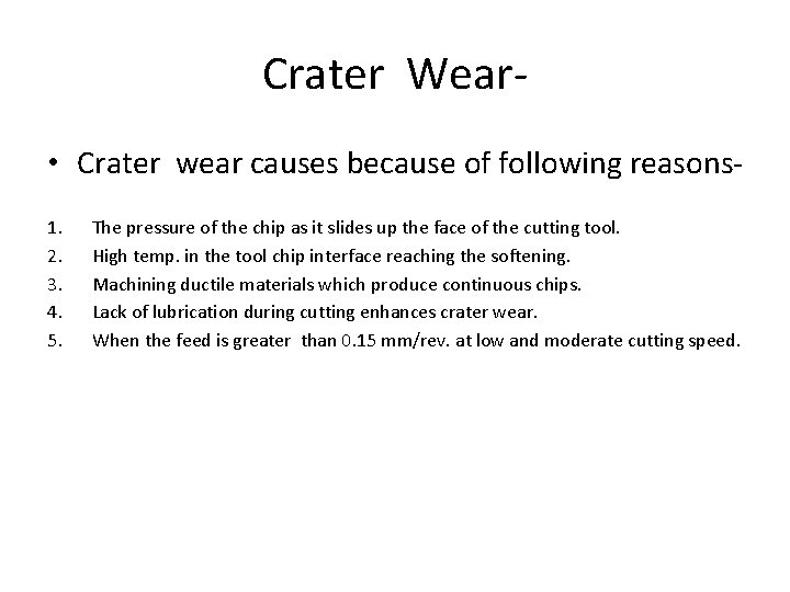
Crater Wear • Crater wear causes because of following reasons 1. 2. 3. 4. 5. The pressure of the chip as it slides up the face of the cutting tool. High temp. in the tool chip interface reaching the softening. Machining ductile materials which produce continuous chips. Lack of lubrication during cutting enhances crater wear. When the feed is greater than 0. 15 mm/rev. at low and moderate cutting speed.
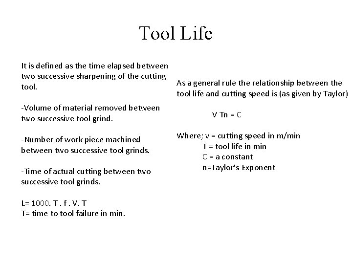
Tool Life It is defined as the time elapsed between two successive sharpening of the cutting As a general rule the relationship between the tool life and cutting speed is (as given by Taylor) -Volume of material removed between two successive tool grind. -Number of work piece machined between two successive tool grinds. -Time of actual cutting between two successive tool grinds. L= 1000. T. f. V. T T= time to tool failure in min. V Tn = C Where; v = cutting speed in m/min T = tool life in min C = a constant n=Taylor’s Exponent
Tool Life Factors affecting Tool life: • • Cutting speed Effect of feed & depth of cut. Physical properties of work piece Profile of cutting tool Area of cut Tool material Cutting fluid Work material Tool life Criteria: • • • Actual cutting time to failure. Length of work cut to failure. Volume of metal removed to failure. Cutting speed for a given time to failure. Number of components produced.
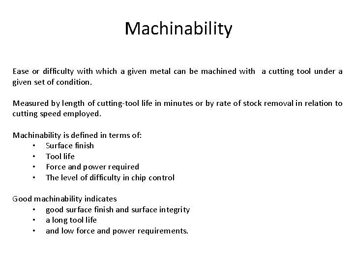
Machinability Ease or difficulty with which a given metal can be machined with a cutting tool under a given set of condition. Measured by length of cutting-tool life in minutes or by rate of stock removal in relation to cutting speed employed. Machinability is defined in terms of: • Surface finish • Tool life • Force and power required • The level of difficulty in chip control Good machinability indicates • good surface finish and surface integrity • a long tool life • and low force and power requirements.
Machinability index
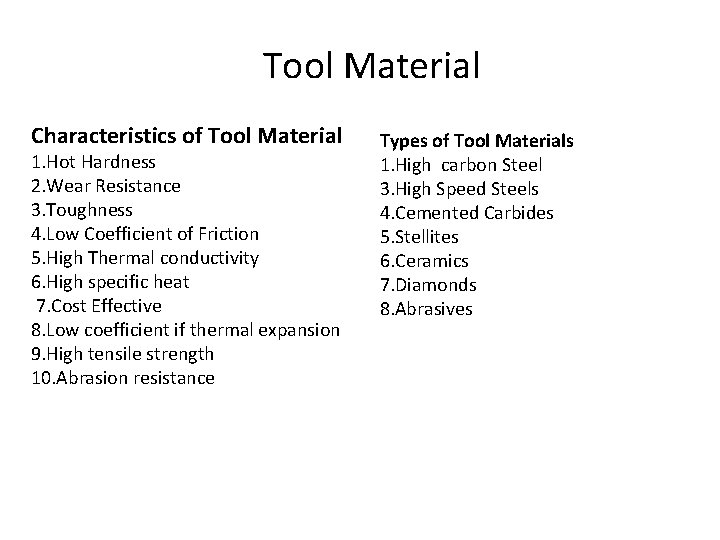
Tool Material Characteristics of Tool Material 1. Hot Hardness 2. Wear Resistance 3. Toughness 4. Low Coefficient of Friction 5. High Thermal conductivity 6. High specific heat 7. Cost Effective 8. Low coefficient if thermal expansion 9. High tensile strength 10. Abrasion resistance Types of Tool Materials 1. High carbon Steel 3. High Speed Steels 4. Cemented Carbides 5. Stellites 6. Ceramics 7. Diamonds 8. Abrasives
Tool Material
Cutting Fluid Cutting fluid is a substance (may be liquid, gas or solid) which is applied to a tool during a cutting to facilitate removal of chips. The use of a cutting fluid will serve to reduce the tool wear, give better surface finish and a tighter dimensional control. Functions of a cutting fluid: • • To cool the cutting tool –chip-w/p interface To lubricate the chip, tool and w/p To help carry away the chips To lubricate some of the moving parts of the m/c tool. To improve the surface finish and protecting finished surface To prevent the formation of BUE To Reduce thermal distortion
Cutting Fluid Properties of Cutting Fluids: • Long life, • Free of excessive oxide formation • Suitable for cutting tools materials and the cutting operations. • Lubricating qualities, • High thermal conductivity • Low viscosity to permit easy flow • Transparent for high dimensional accuracy and fine finish • High Flash Point • Odorless • High heat absorption capacity
Types of Cutting Fluid 1. Soluble oils 2. Cutting oils a) Fixed oils b) Mineral oils 3. Mixture of mineral oils and fixed oils 4. Mixture of mineral oils and fixed oils with EP additives.
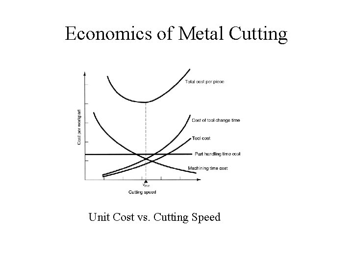
Economics of Metal Cutting Unit Cost vs. Cutting Speed
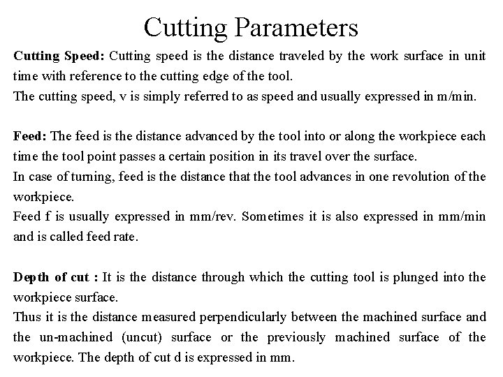
Cutting Parameters Cutting Speed: Cutting speed is the distance traveled by the work surface in unit time with reference to the cutting edge of the tool. The cutting speed, v is simply referred to as speed and usually expressed in m/min. Feed: The feed is the distance advanced by the tool into or along the workpiece each time the tool point passes a certain position in its travel over the surface. In case of turning, feed is the distance that the tool advances in one revolution of the workpiece. Feed f is usually expressed in mm/rev. Sometimes it is also expressed in mm/min and is called feed rate. Depth of cut : It is the distance through which the cutting tool is plunged into the workpiece surface. Thus it is the distance measured perpendicularly between the machined surface and the un-machined (uncut) surface or the previously machined surface of the workpiece. The depth of cut d is expressed in mm.
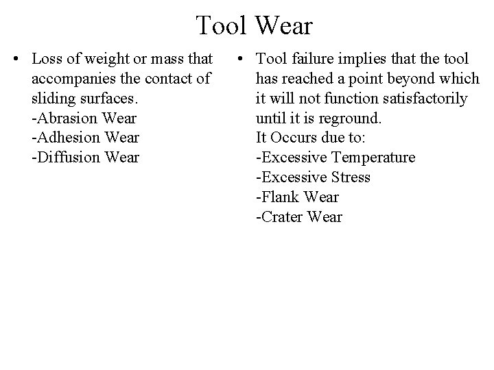
Tool Wear • Loss of weight or mass that accompanies the contact of sliding surfaces. -Abrasion Wear -Adhesion Wear -Diffusion Wear • Tool failure implies that the tool has reached a point beyond which it will not function satisfactorily until it is reground. It Occurs due to: -Excessive Temperature -Excessive Stress -Flank Wear -Crater Wear
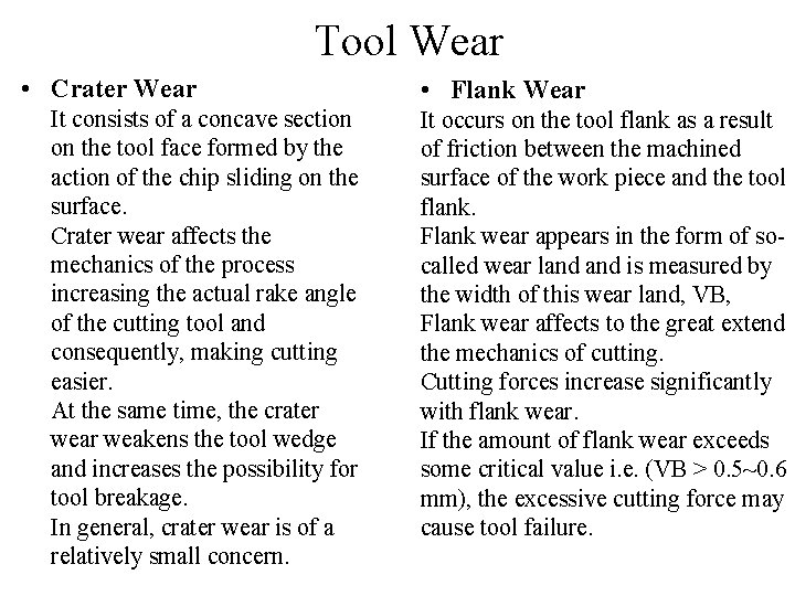
Tool Wear • Crater Wear It consists of a concave section on the tool face formed by the action of the chip sliding on the surface. Crater wear affects the mechanics of the process increasing the actual rake angle of the cutting tool and consequently, making cutting easier. At the same time, the crater weakens the tool wedge and increases the possibility for tool breakage. In general, crater wear is of a relatively small concern. • Flank Wear It occurs on the tool flank as a result of friction between the machined surface of the work piece and the tool flank. Flank wear appears in the form of socalled wear land is measured by the width of this wear land, VB, Flank wear affects to the great extend the mechanics of cutting. Cutting forces increase significantly with flank wear. If the amount of flank wear exceeds some critical value i. e. (VB > 0. 5~0. 6 mm), the excessive cutting force may cause tool failure.
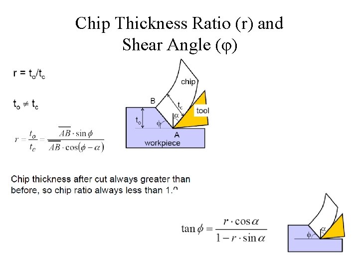
Chip Thickness Ratio (r) and Shear Angle (φ)
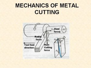
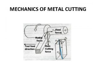
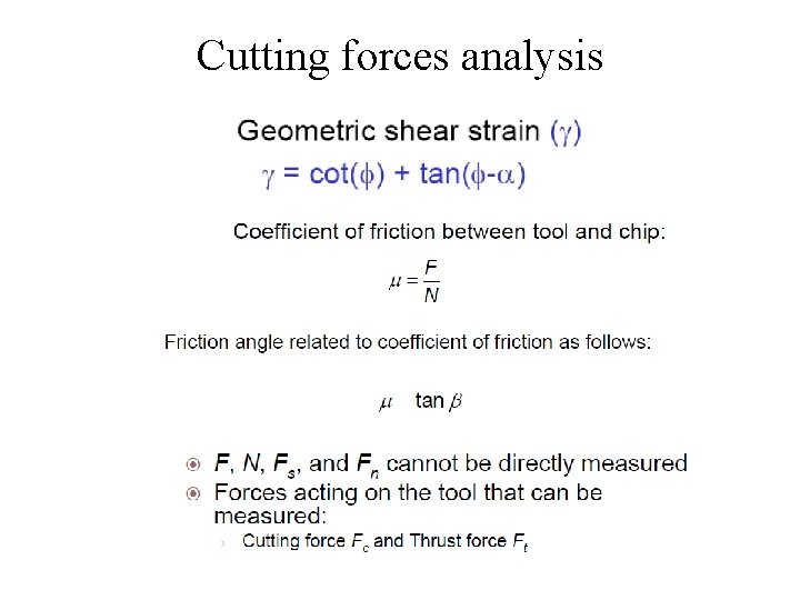
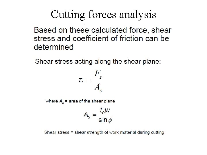
Cutting forces analysis
Cutting forces analysis
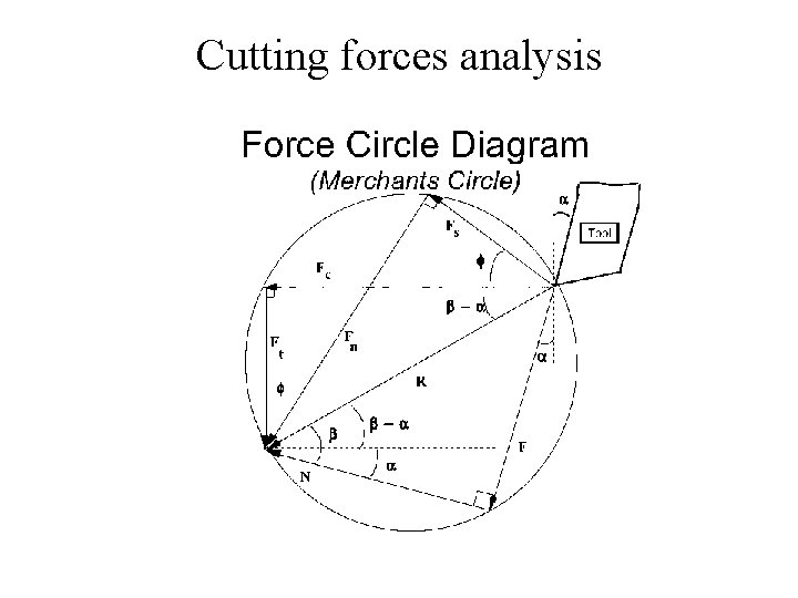
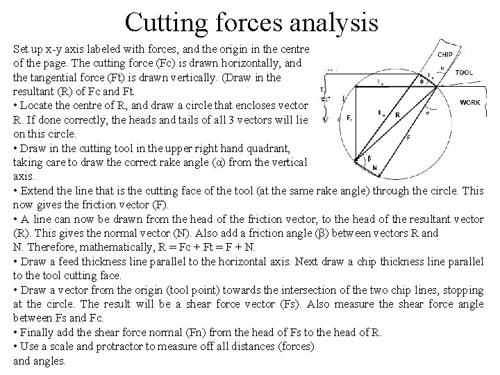
Cutting forces analysis Set up x-y axis labeled with forces, and the origin in the centre of the page. The cutting force (Fc) is drawn horizontally, and the tangential force (Ft) is drawn vertically. (Draw in the resultant (R) of Fc and Ft. • Locate the centre of R, and draw a circle that encloses vector R. If done correctly, the heads and tails of all 3 vectors will lie on this circle. • Draw in the cutting tool in the upper right hand quadrant, taking care to draw the correct rake angle (α) from the vertical axis. • Extend the line that is the cutting face of the tool (at the same rake angle) through the circle. This now gives the friction vector (F). • A line can now be drawn from the head of the friction vector, to the head of the resultant vector (R). This gives the normal vector (N). Also add a friction angle (β) between vectors R and N. Therefore, mathematically, R = Fc + Ft = F + N. • Draw a feed thickness line parallel to the horizontal axis. Next draw a chip thickness line parallel to the tool cutting face. • Draw a vector from the origin (tool point) towards the intersection of the two chip lines, stopping at the circle. The result will be a shear force vector (Fs). Also measure the shear force angle between Fs and Fc. • Finally add the shear force normal (Fn) from the head of Fs to the head of R. • Use a scale and protractor to measure off all distances (forces) and angles.
Cutting forces analysis
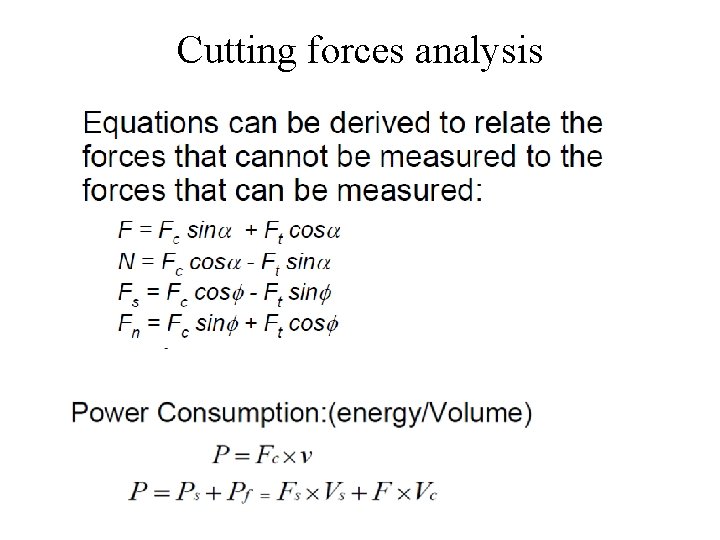
Cutting forces analysis