SVG Scaleable Vector Graphics DBI Representation and Management

SVG – Scaleable Vector Graphics DBI – Representation and Management of Data on the Internet

Representations of images Images can be represented as: § Bitmapped Graphics – storing the RGB values of each pixel in the image § Vector Graphics – storing the coordinates of each vectors and the colors in which they are rendered

Vector Graphics • Vector files store images as a series of descriptions of simple shapes – The image is splited into lines, rectangles, circles etc. – A description of the positions and colors of all of these shapes on the page is given – The image is reconstructucted when the file is opened

Pro’s and Con’s • Vector Graphics are good for – graph – Flowchart • Vector Graphics are not good for – photoes of trees – paintings

Vector Graphics are Scaleable • Vector graphics images are – Easy to resize – Easy to transform

Bitmaps • The whole image is split into a grid of tiny squares, called pixels, and the colour for each pixel in the whole image is recorded • This format allows extremely complex pictures to be described (such as photos) • Becareful – it can produce extremely large file sizes

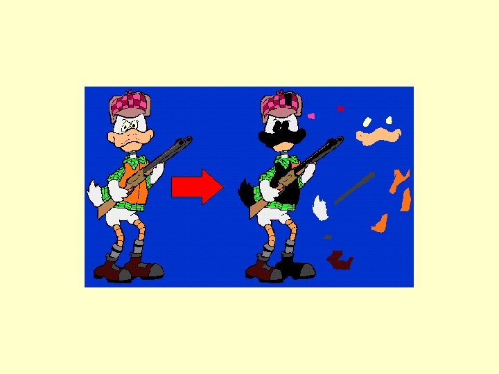
Bitmap Resolution • Enlarging a bitmap image causes to losing resolution:

Transforming Images • It is difficult to change a bitmap image • Transforming a bitmap image to a vector graphics image: – Difficult • Transforming a vector graphics image into a bitmap image – Easy

Compression • In a bitmap there can be areas with many pixels that have the same color – a waste of space • Saving space can be done be reducing the number of colors in the image: Ø 2 bits – 32 bits per pixel • Lossless vs. Lossy compressions

Medium Compression Low Compression High Compression

Non Rectangular Bitmaps

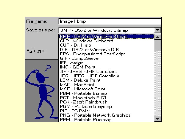
Bitmaps § Main formats for bitmaps: § GIF, § JPEG § BMP § Represented in a binary format § Image processing is done on server side and image is transferred as is to client
 is Compu. Serve's standard for defining")
GIF • Graphic Interchange Format • 'GIF' (tm) is Compu. Serve's standard for defining generalized color raster images

GIF Signature Screen Descriptor Global Color Map Image Descriptor Local Color Map Rester Data Gif Terminator Repeated 1 to n times
 first 1 Screen")
Screen Descriptor 0 0 0 0 Raster width in pixels (LSB) first 1 Screen Width Raster height in pixels (LSB) Screen Height first M = 1, Global color M cr 0 pixel map follows Descriptor +1 = # bits of color resolution background pixel+1 = # bits/pixel in image background=Color index of 0 0 0 0 screen background 2 3 4 5 6 7

Global Color Map red intensity green intensity Color index 0 blue intensity red intensity green intensity Color index 1 blue intensity : :

Image Descriptor 7 6 5 4 3 2 1 Image separator character: ‘, ’ 1 M=0 - Use global color map, ignore 0 0 1 1 0 0 'pixel' 2 Start of image Image left from the left M=1 - Local color map follows, use 3 side 'pixel‘ Start of image from Image top the top of the screen I=0 - Image formatted in Sequential 4 order Image width Width of image 5 Height of image I=1 - Image formatted in Interlaced Image height order 6 pixel+1 - # bits per pixel for this image M I 0 0 0 pixel 7

JPEG • Image compression standard developed by the Joint Photographic Experts Group • Works best on natural images (scenes)
 • The image is divided into 8 by 8")
How Does JPEG Works (Compression) • The image is divided into 8 by 8 pixel blocks • The discrete cosine transform (DCT) of each block is calculated • A quantizer rounds off the DCT coefficients according to the quantization matrix • The coefficients are represented with a variable length code, and the result is written as a compressed data stream to an outputfile (*. jpg)

The Compression 8 x 8 pixel block Discrete Cosine Transform Quantizer Binary Encoder 01001… Output Data stream
 of")
The Discrete Cosine Transform • Separate the image into parts (or spectral sub-bands) of differing importance • The DCT is similar to the discrete Fourier transform: – it transforms a signal or image from the spatial domain to the frequency domain

The Transform • The input image is N 2 pixels wide by N 1 pixels high • A(i, j) is the intensity of the pixel in row i and column j • B(k 1, k 2) is the DCT coefficient in row k 1 and column k 2 of the DCT matrix

Quantization Matrix • The quantization matrix is the 8 by 8 matrix of step sizes (sometimes called quantums) – – one element for each DCT coefficient – it is usually symmetric – step sizes will be small in the upper left (low frequencies), and large in the upper right (high frequencies)

• After quantization, it is not unusual for more than half of the DCT coefficients to equal zero • Compression allows us not to store all the zeros

Decompression • For decompression, – The quantized DCT coefficients are recovered from the compressed data stream by taking the inverse transforms – the image is then decompressed and can be displayed

Lossless Lossy Max Transpa Animat Compres Colo rent ion sion urs 24 -bit BMP 32 -bit TGA TIFF GIF See Note 24 -bit Yes 256 Yes JPEG PNG Yes 24 -bit 48 See Note bit Yes

Vector Graphics § Uses vectors and manipulation of vectors § transformations, § coordinate systems, § units and vector-based shapes § Rendering is done on the client side – § using local processing power § Can be represented in both binary and text formats § Can include Bitmap images

Other Graphics Formats • • • SVG – Simple Vector Format DWF – Drawing Web Format Flash – Macromedia’s Vector Graphics VML – Vector Markup Language VRML – Virtual Reality Modeling Language

Vectors vs. Bitmaps • For simple shapes and images vector graphics saves space • Vectors are easy to transform • Vectors are scaleable • Vector representation can be textual (xml) instead of binary

SVG § SVG stands for Scalable Vector Graphics § In terms of graphics, scalable means not being limited to single, fixed units § SVG graphics is scalable to different display resolutions and color spaces § The same SVG graphic can be placed at different sizes on the same Web page, and re-used at different sizes on different pages § SVG graphics can be magnified to see fine detail, or to aid those with low vision

SVG Code Example <? xml version="1. 0 ”standalone="no"? > <!DOCTYPE svg PUBLIC "-//W 3 C//DTD SVG 20001102//EN" "http: //www. w 3. org/TR/2000/CR-SVG -20001102/DTD/svg-20001102. dtd"> <svg width=” 300 px" height=” 200 px"> <desc> <!-- put a description here --> </desc> <g> <!-- your graphic here --> </g> </svg>

<? xml version="1. 0" standalone="no"? > <!DOCTYPE svg PUBLIC "-//W 3 C//DTD SVG 20001102//EN" "http: //www. w 3. org/TR/2000/CR-SVG 20001102/DTD/svg-20001102. dtd"> <svg width="5 cm" height="4 cm"> <desc> Four separate rectangles </desc> <rect x="0. 5 cm" y="0. 5 cm" width="2 cm" height="1 cm"/> <rect x="0. 5 cm" y="2 cm" width="1 cm" height="1. 5 cm"/> <rect x="3 cm" y="0. 5 cm" width="1. 5 cm" height="2 cm"/> <rect x="3. 5 cm" y="3 cm" width="1 cm" height="0. 5 cm"/> </svg>

Grouping with <g< <? xml version="1. 0" standalone="no"? > <!DOCTYPE svg PUBLIC "-//W 3 C//DTD SVG 20001102//EN" "http: //www. w 3. org/TR/2000/CR-SVG-20001102/DTD/svg 20001102. dtd"> <svg width="5 cm" height="5 cm"> <desc>Two groups, each of two rectangles </desc> <g id="group 1" style="fill: red"> <rect x="1 cm" y="1 cm" width="1 cm" height="1 cm" /> <rect x="3 cm" y="1 cm" width="1 cm" height="1 cm" /> </g> <g id="group 2" style="fill: blue"> <rect x="1 cm" y="3 cm" width="1 cm" height="1 cm" /> <rect x="3 cm" y="3 cm" width="1 cm" height="1 cm" /> </g> </svg> Allows Adding Style

Using a Namespace <? xml version="1. 0 ”standalone="no"? > <svg width=” 300 px" height=” 200 px” xmlns = 'http: //www. w 3. org/2000/svg ’> <desc> <!-- put a description here --> </desc> <g> <!-- your graphic here --> </g> </svg>

Images Insertion 1. The <image> tag indicates that the contents of a complete file are to be rendered into a given rectangle within the current user coordinate system 2. The <image> can refer to raster image files such as PNG or JPEG or to an SVG file 3. Main attributes: “x”, “y”, “width”, “height” and “xlink: href”

Adding Text § <text> is used to specify text that is rendered with other graphical elements § This means that we can apply transformations, clippings, maskings, etc. to text § Fonts are as specified in CSS 2

Text Example <? xml version="1. 0" standalone="no"? > <!DOCTYPE svg PUBLIC "-//W 3 C//DTD SVG 20001102//EN" "http: //www. w 3. org/TR/2000/CR-SVG-20001102/DTD/svg 20001102. dtd"> <svg width="10 cm" height="3 cm"> <desc>Example text 01 - 'Hello, out there' in blue</desc> <text x="2. 5 cm" y="1. 5 cm" style="font-family: Verdana; fontsize: 16 pt; fill: blue"> Hello, out there </text> </svg>

Shapes and Lines • For shapes and lines we use the tags: § <rect> § <circle> § <ellipse> § <line> § <polygon>

Animation § SVG supports the ability to change vector graphics over time § There are 2 main ways for animating SVG content: § Through SVG animation elements § By access to the SVG DOM

§ Main animation elements in SVG: § ‘animate’ , ‘set’, ‘animate. Motion’, ‘animate. Color’, ‘animate. Transform’ § Animation introduces the time dimension to the document § Time notion in SVG: § document begin – when <svg>’s onload event was triggered § document end – when <svg>’s resources have been released

Coordinate System § There are two coordinate systems in SVG: § Viewport coordinate system – positive integer numbers representing pixels. § User coordinate system – real numbers, this is the coordinate system as the user sees it. § Usually the origin of both coordinate systems are identical and each pixel in the viewport is mapped to one unit in user coordinate system. § The viewbox attribute can be used to change this mapping.

Transformations § A new user coordinate system can be established by specifying transformations in the form of a transform attribute on a group of graphical elements. § The transform attribute transforms all user space coordinates and lengths on the given element and all of its ancestors. § Transformations maybe nested and so have cummulative effect.

Transformation Matrix 1. 2 D transformations are represented using 3 X 3 matrices. 2. Common transformations: translate(x, y) - establish a new coordinate system whose origin is at (x, y). rotate(a) – rotates the coordinate system by a degrees around the origin. scale(a, b) – scales the coordinate system – x axis by a and y axis by b.

Transformations § Translation Matrix: § Rotation Matrix: § Scaling Matrix:

Applying Transformations § SVG allows both to apply transformations as translate, rotate, scale or to apply a detailed transformation matrix § Transformations in SVG are applied by the ‘transform’ element.
 §")
SMIL § SVG is a host language in terms of SMIL (Synchronized Multimedia) § Animation and therefore introduces additional constraints and features as permitted by that specification § It also introduces new extensions compatible with SMIL
- Slides: 48