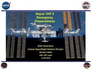
Soyuz VHF 2 Emergency Preparedness Mark Severance Human
- Slides: 67
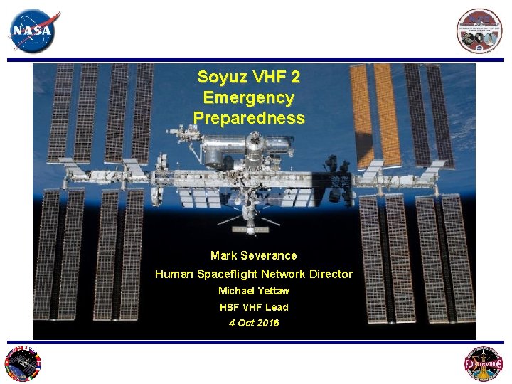
Soyuz VHF 2 Emergency Preparedness Mark Severance Human Spaceflight Network Director Michael Yettaw HSF VHF Lead 4 Oct 2016
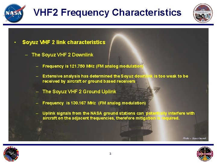
VHF 2 Frequency Characteristics • Soyuz VHF 2 link characteristics – The Soyuz VHF 2 Downlink – Frequency is 121. 750 MHz (FM analog modulation) – Extensive analysis has determined the Soyuz downlink is too weak to be received by aircraft or ground based receivers – The Soyuz VHF 2 Ground Uplink – Frequency is 130. 167 MHz (FM analog modulation) – Uplink signals from the NASA ground stations can potentially interfere with aircraft on the adjacent frequencies, therefore mitigation is required. Photo – Soyuz launch 2
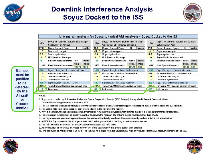
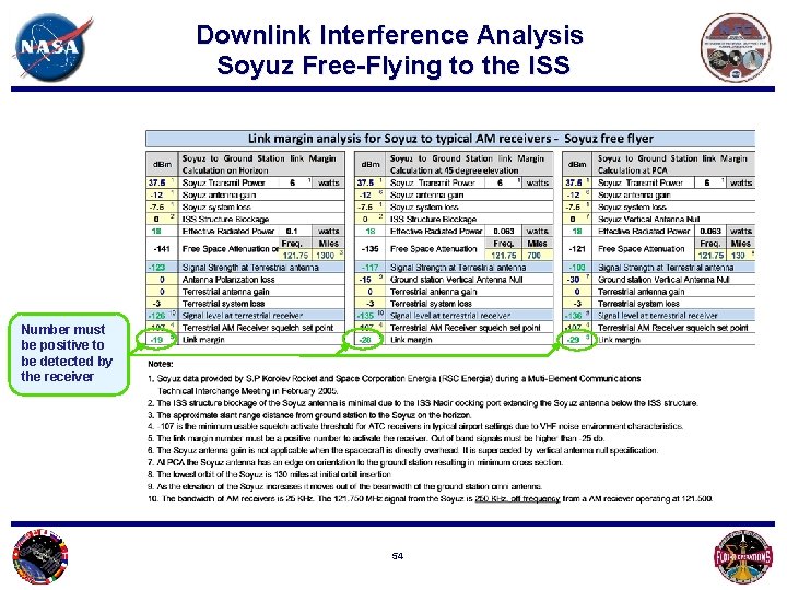
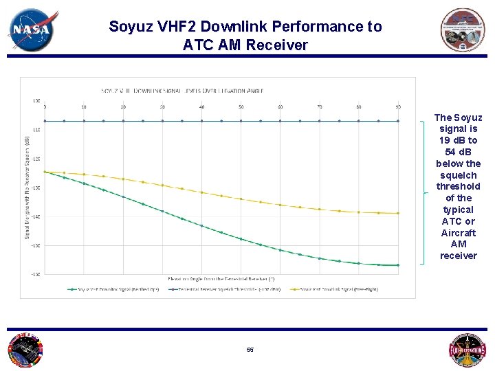
Downlink Interference Analysis Conclusions • The Soyuz downlink signal level does not exceed -126 d. Bm. This signal level is more than 19 d. B below the typical squelch threshold of the typical AM receivers. • The Soyuz downlink signal cannot interfere with ground or airborne AM receivers The FAA concluded in October 2015 that the Soyuz VHF 2 downlink will not cause harmful interference to FAA users. FAA supports annual emergency preparedness testing through operational coordination with affected users by VHF 2 uplink from NASA Ground Stations. Photo – Soyuz Launch 3
Soyuz VHF 2 Uplink Interference Analysis Photo – Milky way from ISS 4
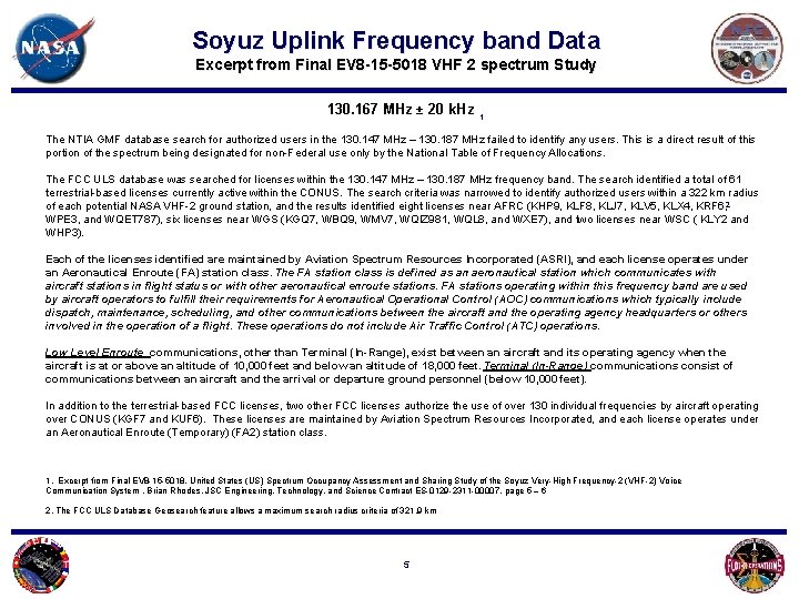
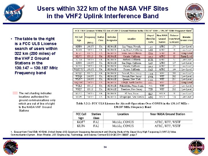
Soyuz Uplink Frequency band Data Excerpt from Final EV 8 -15 -5018 VHF 2 spectrum Study 130. 167 MHz ± 20 k. Hz 1 The NTIA GMF database search for authorized users in the 130. 147 MHz – 130. 187 MHz failed to identify any users. This is a direct result of this portion of the spectrum being designated for non-Federal use only by the National Table of Frequency Allocations. The FCC ULS database was searched for licenses within the 130. 147 MHz – 130. 187 MHz frequency band. The search identified a total of 61 terrestrial-based licenses currently active within the CONUS. The search criteria was narrowed to identify authorized users within a 322 km radius 2 of each potential NASA VHF-2 ground station, and the results identified eight licenses near AFRC (KHP 9, KLF 8, KLJ 7, KLV 5, KLX 4, KRF 6, WPE 3, and WQET 787), six licenses near WGS (KGQ 7, WBQ 9, WMV 7, WQIZ 981, WQL 8, and WXE 7), and two licenses near WSC ( KLY 2 and WHP 3). Each of the licenses identified are maintained by Aviation Spectrum Resources Incorporated (ASRI), and each license operates under an Aeronautical Enroute (FA) station class. The FA station class is defined as an aeronautical station which communicates with aircraft stations in flight status or with other aeronautical enroute stations. FA stations operating within this frequency band are used by aircraft operators to fulfill their requirements for Aeronautical Operational Control (AOC) communications which typically include dispatch, maintenance, scheduling, and other communications between the aircraft and the operating agency headquarters or others involved in the operation of a flight. These operations do not include Air Traffic Control (ATC) operations. Low Level Enroute communications, other than Terminal (In-Range), exist between an aircraft and its operating agency when the aircraft is at or above an altitude of 10, 000 feet and below an altitude of 18, 000 feet. Terminal (In-Range) communications consist of communications between an aircraft and the arrival or departure ground personnel (below 10, 000 feet). In addition to the terrestrial-based FCC licenses, two other FCC licenses authorize the use of over 130 individual frequencies by aircraft operating over CONUS (KGF 7 and KUF 6). These licenses are maintained by Aviation Spectrum Resources Incorporated, and each license operates under an Aeronautical Enroute (Temporary) (FA 2) station class. 1. Excerpt from Final EV 8 -15 -5018, United States (US) Spectrum Occupancy Assessment and Sharing Study of the Soyuz Very-High Frequency-2 (VHF-2) Voice Communication System , Brian Rhodes, JSC Engineering, Technology, and Science Contract ES-0129 -2311 -00007, page 5 – 6 2. The FCC ULS Database Geosearch feature allows a maximum search radius criteria of 321. 9 km 5
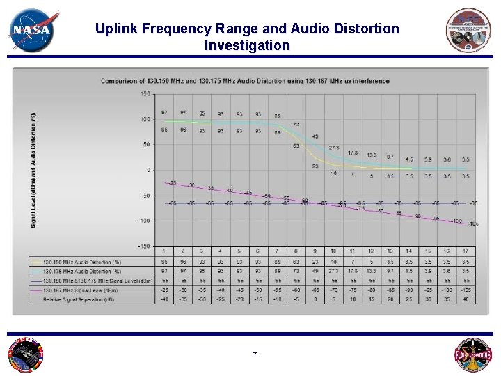
Interference Test Summary results • A test was conducted at Armstrong Flight Research Center (AFRC) to determine the potential interference bandwidth of the VHF 2 Ground Station 130. 167 MHz uplink signal on typical AM receivers – VHF 2 uplink induced receiver distortion was detected during testing when operating on frequencies from 130. 1225 MHz to 130. 225 MHz on a URC-200 test Receiver using an interference source of 130. 167 MHz • This yielded - 44. 5 k. Hz to +55 k. Hz interference bandwidth – Interference becomes apparent (> 10% distortion) if the VHF 2 Ground Station transmitter signal is within: • 20 d. B of the 130. 175 MHz frequency. • 5 d. B of the 130. 150 MHz frequency. Photo – Nile from ISS 6
Uplink Frequency Range and Audio Distortion Investigation 7
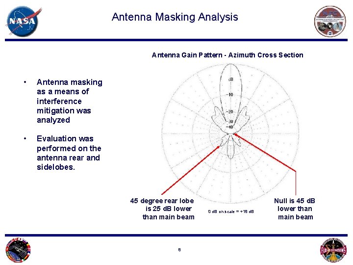
Antenna Masking Analysis Antenna Gain Pattern - Azimuth Cross Section • Antenna masking as a means of interference mitigation was analyzed • Evaluation was performed on the antenna rear and sidelobes. 45 degree rear lobe is 25 d. B lower than main beam 8 0 d. B on scale = +18 d. B Null is 45 d. B lower than main beam
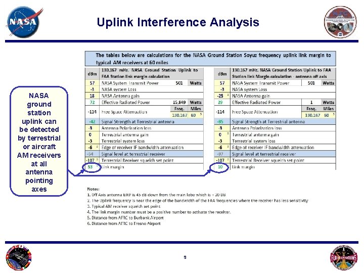
Uplink Interference Analysis NASA ground station uplink can be detected by terrestrial or aircraft AM receivers at all antenna pointing axes 9
Uplink Adjacent Frequency Interference Test Data Results Synopsis • VHF 2 uplink can be detected on frequencies from 130. 1225 MHz to 130. 225 MHz • The gain pattern of the VHF 2 Ground Station antenna is approximately 25 to 45 d. B lower than the peak gain at 90 degrees off boresight. This gain difference is insufficient for uplink interference mitigation. • Terrain blockage is not viable for 100% interference mitigation. • Interference mitigation is possible if uplink transmission occurs during non- flight periods of frequency license holders in the interference band. Photo – Texas at night from ISS 10
Soyuz VHF 2 Ground Station Interference Range Radius Study 11
• The following data was used to determine the Soyuz VHF 2 uplink potential interference distance • Calculations were done with the following assumptions • As a general rule commercial aircraft descents occur over a longer distance than climb to altitudes • It is understood that aircraft Top of Descent distances vary • It is understood that Stepped Descents will add distance to a commercial airliner approach 12
• Commercial Airliner Approach Distance Data was evaluated to determine the scope of the interference window Photo – Sunrise over Western US from ISS 13
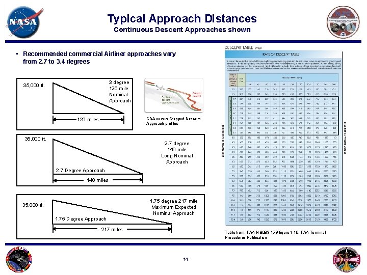
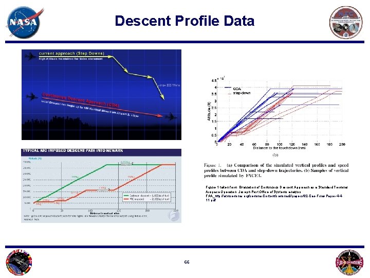
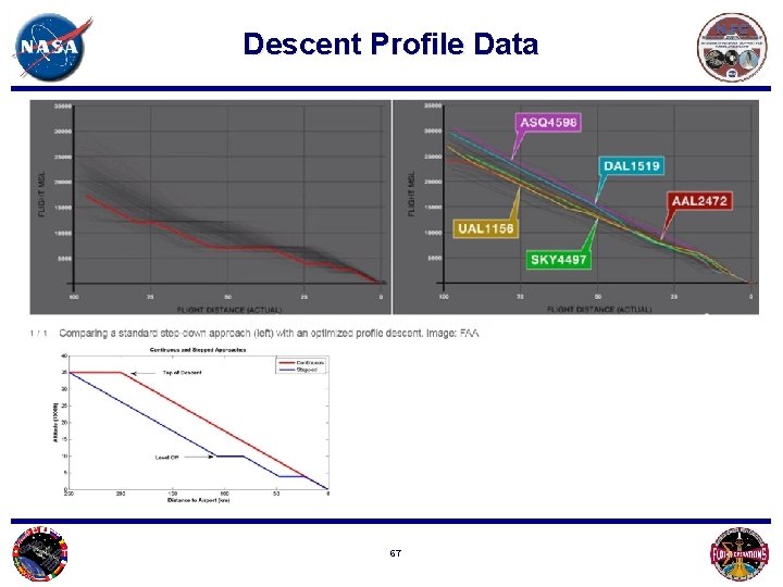
Typical Approach Distances Continuous Descent Approaches shown • Recommended commercial Airliner approaches vary from 2. 7 to 3. 4 degrees 3 degree 126 mile Nominal Approach 35, 000 ft. CDA versus Stepped Descent Approach profiles 126 miles 35, 000 ft. 2. 7 degree 140 mile Long Nominal Approach 2. 7 Degree Approach 140 miles 1. 75 degree 217 mile Maximum Expected Nominal Approach 35, 000 ft. 1. 75 Degree Approach 217 miles Table from: FAA-H-8083 -15 B figure 1 -19, FAA Terminal Procedures Publication 14
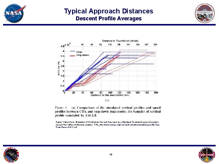
Typical Approach Distances Descent Profile Averages Distance to Touchdown (miles) 46 69 92 115 138 161 184 207 230 Figure 1 taken from: Evaluation of Continuous Descent Approach as a Standard Terminal Airspace Operation. Joseph Post Office of Systems analysis, FAA_http: //atmseminar. org/seminar. Content/seminar 9/papers/62 -Cao. Final-Paper-4 -4 -11. pdf 15
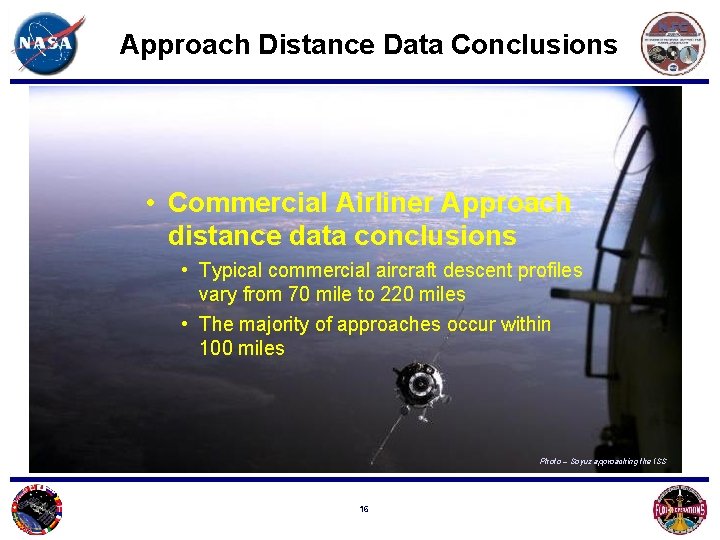
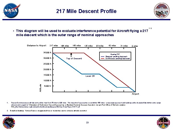
Approach Distance Data Conclusions • Commercial Airliner Approach distance data conclusions • Typical commercial aircraft descent profiles vary from 70 mile to 220 miles • The majority of approaches occur within 100 miles Photo – Soyuz approaching the ISS 16
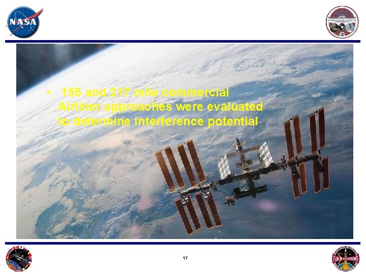
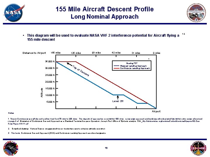
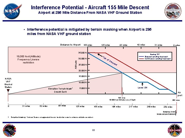
• 155 and 217 mile commercial Airliner approaches were evaluated to determine interference potential 17
155 Mile Aircraft Descent Profile Long Nominal Approach • This diagram will be used to evaluate NASA VHF 2 interference potential for Aircraft flying a 155 mile descent Distance to Airport 155 miles 62 miles 93 miles 125 miles 31 miles 1, 2 0 miles 1 35, 000 ft. 30, 000 ft. 25, 000 ft. To po f. D Boeing 737 Stepped Landing Approach Continuous Landing Approach es ce nt Altitude 20, 000 ft. 15, 000 ft. 10, 000 ft. Level Off 5, 000 ft. Airport Notes: 1. Typical Commercial aircraft descent profiles vary from 70 mile to 220 miles. The majority of approaches occur within 100 miles. Long range approach and landing profile displayed falls within outer range referenced in page 2 of Evaluation of Continuous Descent Approach as a Standard Terminal Airspace Operation. Joseph Post Office of Systems analysis FAA_http: //atmseminar. org/seminar. Content/seminar 9/papers/62 -Cao. Final-Paper-4 -4 -11. pdf 2. Simplified drawing. Vertical Scale is exaggerated versus horizontal scale to enhance altitude resolution. 3. The terms Continuous Descent Approach (CDA) and Continuous Landing Approach are interchangeable 18
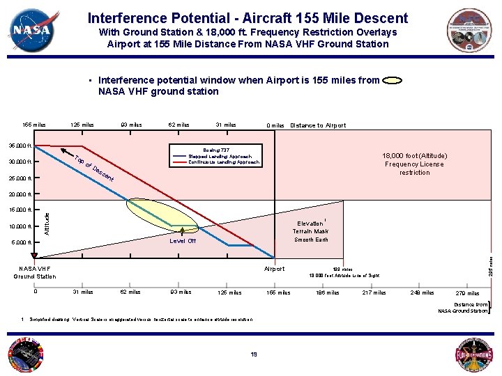
Interference Potential - Aircraft 155 Mile Descent With Ground Station & 18, 000 ft. Frequency Restriction Overlays Airport at 155 Mile Distance From NASA VHF Ground Station • Interference potential window when Airport is 155 miles from NASA VHF ground station 155 miles 93 miles 125 miles 35, 000 ft. To 30, 000 ft. 62 miles 31 miles 0 miles Distance to Airport Boeing 737 Stepped Landing Approach Continuous Landing Approach po f. D es 18, 000 foot (Altitude) Frequency License restriction ce 25, 000 ft. nt 20, 000 ft. Altitude 10, 000 ft. 1 Elevation Terrain Mask Smooth Earth Level Off 5, 000 ft. Airport NASA VHF Ground Station 0 31 miles 62 miles 93 miles 125 miles 155 miles 295 miles 15, 000 ft. 199 miles 18, 000 foot Altitude Line of Sight 186 miles 217 miles 248 miles 279 miles Distance From NASA Ground Station 1. Simplified drawing. Vertical Scale is exaggerated versus horizontal scale to enhance altitude resolution. 19
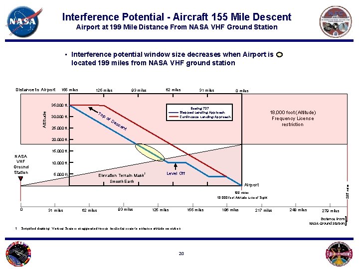
Interference Potential - Aircraft 155 Mile Descent Airport at 199 Mile Distance From NASA VHF Ground Station • Interference potential window size decreases when Airport is located 199 miles from NASA VHF ground station Distance to Airport 155 miles 93 miles 125 miles 62 miles Altitude 35, 000 ft. 0 miles Boeing 737 Stepped Landing Approach Continuous Landing Approach To po 30, 000 ft. 31 miles f. D es 18, 000 foot (Altitude) Frequency License restriction ce 25, 000 ft. nt 20, 000 ft. 15, 000 ft. 10, 000 ft. 5, 000 ft. Elevation Terrain Mask 1 Level Off Smooth Earth Airport 295 miles NASA VHF Ground Station 199 miles 18, 000 foot Altitude Line of Sight 0 31 miles 62 miles 93 miles 125 miles 155 miles 186 miles 217 miles 248 miles 279 miles Distance From NASA Ground Station 1. Simplified drawing. Vertical Scale is exaggerated versus horizontal scale to enhance altitude resolution. 20
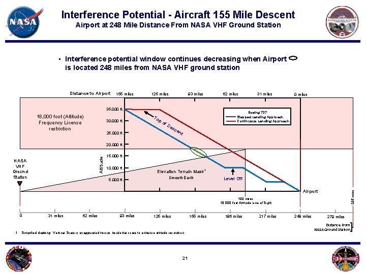
Interference Potential - Aircraft 155 Mile Descent Airport at 248 Mile Distance From NASA VHF Ground Station • Interference potential window continues decreasing when Airport is located 248 miles from NASA VHF ground station Distance to Airport 155 miles 62 miles 93 miles 125 miles 35, 000 ft. 18, 000 foot (Altitude) Frequency License restriction 30, 000 ft. To po f. D 31 miles 0 miles Boeing 737 Stepped Landing Approach Continuous Landing Approach es 25, 000 ft. ce nt Altitude 20, 000 ft. NASA VHF Ground Station 15, 000 ft. 10, 000 ft. 5, 000 ft. Elevation Terrain Mask 1 Smooth Earth Level Off 295 miles Airport 199 miles 18, 000 foot Altitude Line of Sight 0 31 miles 62 miles 93 miles 125 miles 155 miles 1. Simplified drawing. Vertical Scale is exaggerated versus horizontal scale to enhance altitude resolution. 21 186 miles 217 miles 248 miles 279 miles Distance From NASA Ground Station
Interference Potential - Aircraft 155 Mile Descent Airport at 295 Mile Distance From NASA VHF Ground Station • Interference potential is mitigated by terrain masking when Airport is 295 miles from NASA VHF ground station Distance to Airport 155 miles 62 miles 93 miles 125 miles 35, 000 ft. 18, 000 foot (Altitude) Frequency License restriction To Altitude 30, 000 ft. 25, 000 ft. po f. D 31 miles 0 miles Boeing 737 Stepped Landing Approach Continuous Landing Approach es ce nt 20, 000 ft. 15, 000 ft. NASA VHF Ground Station 10, 000 ft. Elevation Terrain Mask 1 Level Off 5, 000 ft. Smooth Earth Air port 199 miles 18, 000 foot Altitude Line of Sight 0 31 miles 62 miles 93 miles 125 miles 155 miles 186 miles 217 miles 295 miles 248 miles 279 miles Distance From NASA Ground Station 1. Simplified drawing. Vertical Scale is exaggerated versus horizontal scale to enhance altitude resolution. 22
217 Mile Descent Profile • This diagram will be used to evaluate interference potential for Aircraft flying a 217 mile descent which is the outer range of nominal approaches Distance to Airport 217 miles 186 miles 155 miles 125 miles 35, 000 ft. 30, 000 ft. 93 miles 62 miles 31 miles 1, 2 0 miles Boeing 737 Stepped Landing Approach Continuous Landing Approach Top of Descent 25, 000 ft. 20, 000 ft. 15, 000 ft. Level Off Altitude 10, 000 ft. 5, 000 ft. Airport 1. Typical Commercial aircraft descent profiles vary from 70 mile to 220 miles. The majority of approaches occur within 100 miles. Long range approach and landing profile displayed falls within outer range referenced in page 2 of Evaluation of Continuous Descent Approach as a Standard Terminal Airspace Operation. Joseph Post Office of Systems analysis FAA_http: //atmseminar. org/seminar. Content/seminar 9/papers/62 -Cao-Final-Paper-4 -4 -11. pdf 2. Simplified drawing. Vertical Scale is exaggerated versus horizontal scale to enhance altitude resolution. 23
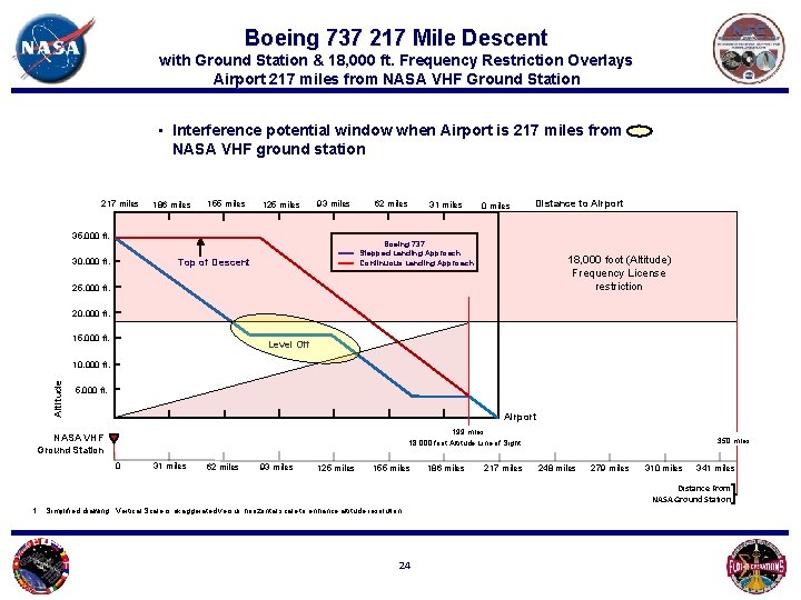
Boeing 737 217 Mile Descent with Ground Station & 18, 000 ft. Frequency Restriction Overlays Airport 217 miles from NASA VHF Ground Station • Interference potential window when Airport is 217 miles from NASA VHF ground station 217 miles 186 miles 155 miles 125 miles 93 miles 35, 000 ft. 30, 000 ft. 62 miles 31 miles 0 miles Distance to Airport Boeing 737 Stepped Landing Approach Continuous Landing Approach Top of Descent 18, 000 foot (Altitude) Frequency License restriction 25, 000 ft. 20, 000 ft. 15, 000 ft. Level Off Altitude 10, 000 ft. 5, 000 ft. Airport 199 miles 18, 000 foot Altitude Line of Sight NASA VHF Ground Station 0 31 miles 62 miles 93 miles 125 miles 155 miles 186 miles 217 miles 350 miles 248 miles 279 miles 310 miles 341 miles Distance From NASA Ground Station 1. Simplified drawing. Vertical Scale is exaggerated versus horizontal scale to enhance altitude resolution. 24
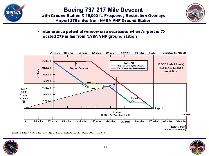
Boeing 737 217 Mile Descent with Ground Station & 18, 000 ft. Frequency Restriction Overlays Airport 279 miles from NASA VHF Ground Station • Interference potential window size decreases when Airport is located 279 miles from NASA VHF ground station 217 miles 186 miles 155 miles 93 miles 125 miles Altitude 35, 000 ft. 30, 000 ft. 62 miles 31 miles Boeing 737 Stepped Landing Approach Continuous Landing Approach Top of Descent Distance to Airport 0 miles 18, 000 foot (Altitude) Frequency License restriction 25, 000 ft. 20, 000 ft. NASA VHF Ground Station 15, 000 ft. 10, 000 ft. Level Off 5, 000 ft. Airport 199 miles 18, 000 foot Altitude Line of Sight 0 31 miles 62 miles 93 miles 125 miles 155 miles 186 miles 217 miles 350 miles 248 miles 279 miles 310 miles 341 miles Distance From NASA Ground Station 1. Simplified drawing. Vertical Scale is exaggerated versus horizontal scale to enhance altitude resolution. 25
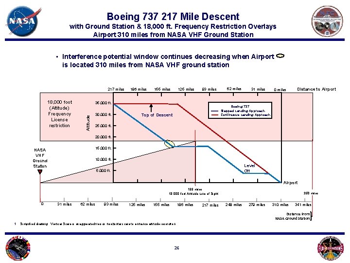
Boeing 737 217 Mile Descent with Ground Station & 18, 000 ft. Frequency Restriction Overlays Airport 310 miles from NASA VHF Ground Station • Interference potential window continues decreasing when Airport is located 310 miles from NASA VHF ground station 217 miles 155 miles 125 miles 93 miles 35, 000 ft. Altitude 18, 000 foot (Altitude) Frequency License restriction 186 miles 30, 000 ft. 62 miles 31 miles 0 miles Distance to Airport Boeing 737 Stepped Landing Approach Continuous Landing Approach Top of Descent 25, 000 ft. 20, 000 ft. 15, 000 ft. NASA VHF Ground Station 10, 000 ft. Level Off 5, 000 ft. Airport 199 miles 18, 000 foot Altitude Line of Sight 0 31 miles 62 miles 93 miles 125 miles 155 miles 186 miles 217 miles 350 miles 248 miles 279 miles 310 miles 341 miles Distance From NASA Ground Station 1. Simplified drawing. Vertical Scale is exaggerated versus horizontal scale to enhance altitude resolution. 26
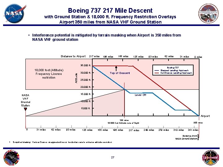
Boeing 737 217 Mile Descent with Ground Station & 18, 000 ft. Frequency Restriction Overlays Airport 350 miles from NASA VHF Ground Station • Interference potential is mitigated by terrain masking when Airport is 350 miles from NASA VHF ground station Distance to Airport 217 miles 186 miles 155 miles 125 miles 93 miles 18, 000 foot (Altitude) Frequency License restriction Altitude 35, 000 ft. 30, 000 ft. 62 miles 31 miles 0 miles Boeing 737 Stepped Landing Approach Continuous Landing Approach Top of Descent 25, 000 ft. 20, 000 ft. 15, 000 ft. NASA VHF Ground Station Level Off 10, 000 ft. 5, 000 ft. Airport 199 miles 18, 000 foot Altitude Line of Sight 0 31 miles 62 miles 93 miles 125 miles 155 miles 186 miles 217 miles 350 miles 248 miles 279 miles 310 miles 341 miles Distance From NASA Ground Station 1. Simplified drawing. Vertical Scale is exaggerated versus horizontal scale to enhance altitude resolution. 27
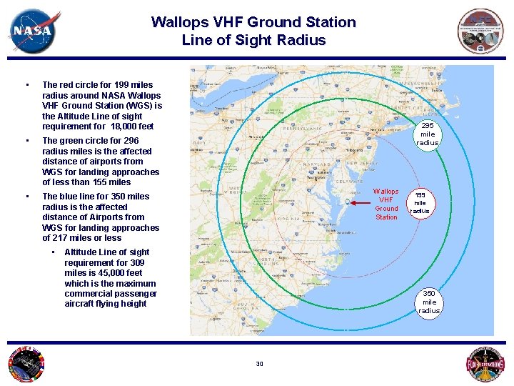
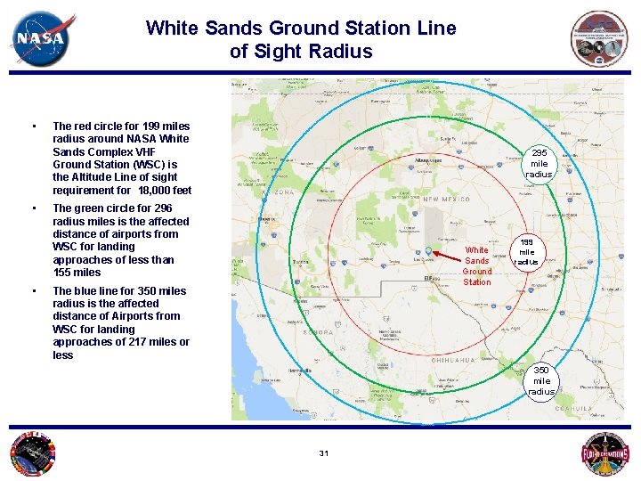
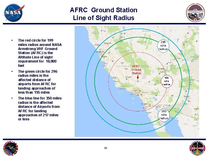
Distance Calculations • The following pages list parameters for the three NASA VHF Ground Stations including : • 199 Mile 18, 000 foot direct Line of Sight radius • 295 Mile nominal aircraft descent path radius • 350 Mile long approach descent path radius 28
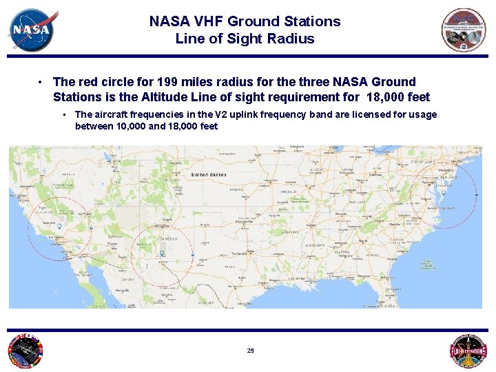
NASA VHF Ground Stations Line of Sight Radius • The red circle for 199 miles radius for the three NASA Ground Stations is the Altitude Line of sight requirement for 18, 000 feet • The aircraft frequencies in the V 2 uplink frequency band are licensed for usage between 10, 000 and 18, 000 feet 29
Wallops VHF Ground Station Line of Sight Radius • The red circle for 199 miles radius around NASA Wallops VHF Ground Station (WGS) is the Altitude Line of sight requirement for 18, 000 feet • The green circle for 296 radius miles is the affected distance of airports from WGS for landing approaches of less than 155 miles • The blue line for 350 miles radius is the affected distance of Airports from WGS for landing approaches of 217 miles or less • 295 mile radius Wallops VHF Ground Station Altitude Line of sight requirement for 309 miles is 45, 000 feet which is the maximum commercial passenger aircraft flying height 199 mile radius 350 mile radius 30
White Sands Ground Station Line of Sight Radius • • • The red circle for 199 miles radius around NASA White Sands Complex VHF Ground Station (WSC) is the Altitude Line of sight requirement for 18, 000 feet 295 mile radius The green circle for 296 radius miles is the affected distance of airports from WSC for landing approaches of less than 155 miles White Sands Ground Station The blue line for 350 miles radius is the affected distance of Airports from WSC for landing approaches of 217 miles or less 199 mile radius 350 mile radius 31
AFRC Ground Station Line of Sight Radius • • • The red circle for 199 miles radius around NASA Armstrong VHF Ground Station (AFRC) is the Altitude Line of sight requirement for 18, 000 feet 295 mile radius AFRC Ground Station The green circle for 296 radius miles is the affected distance of airports from AFRC for landing approaches of less than 155 miles 199 mile radius The blue line for 350 miles radius is the affected distance of Airports from AFRC for landing approaches of 217 miles or less 350 mile radius 32
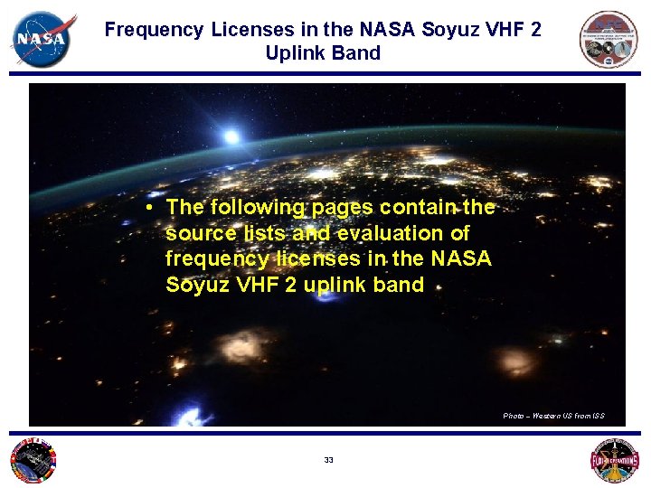
Frequency Licenses in the NASA Soyuz VHF 2 Uplink Band • The following pages contain the source lists and evaluation of frequency licenses in the NASA Soyuz VHF 2 uplink band Photo – Western US from ISS 33
Users within 322 km of the NASA VHF Sites in the VHF 2 Uplink Interference Band 1 • The table to the right is a FCC ULS License search of users within 322 km (200 miles) of the VHF 2 Ground Stations in the 130. 147 – 130. 187 MHz Frequency band The red shading indicates locations authorized for ground communications only which are out of line of sight to the NASA VHF Ground Stations 1. Excerpt from Final EV 8 -15 -5018, United States (US) Spectrum Occupancy Assessment and Sharing Study of the Soyuz Very-High Frequency-2 (VHF-2) Voice Communication System , Brian Rhodes, JSC Engineering, Technology, and Science Contract ES-0129 -2311 -00007, page 7 34
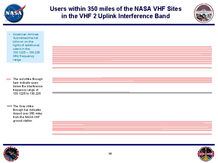
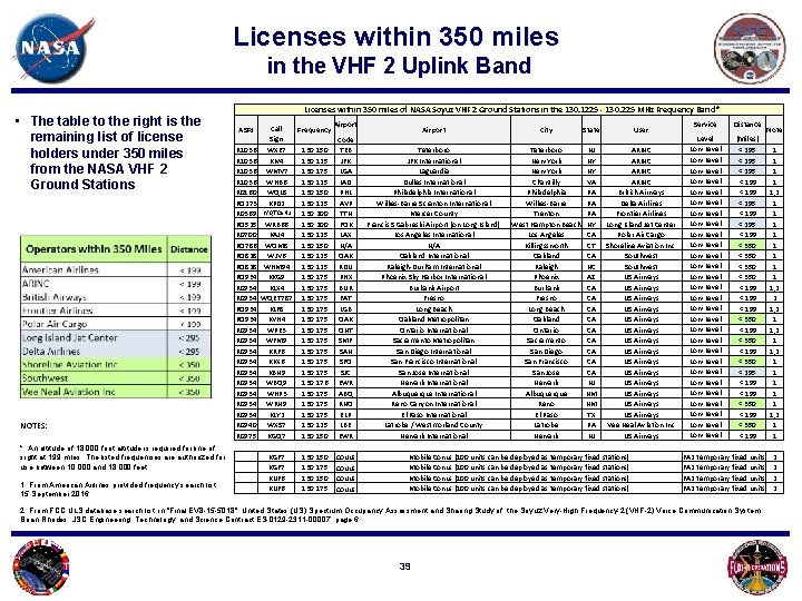
Users within 350 miles of the NASA VHF Sites in the VHF 2 Uplink Interference Band • American Airlines Submitted the list (shown on the right) of additional users in the 130. 1225 – 130. 225 MHz frequency range The red strike through bars indicate users below the interference frequency range of 130. 1225 to 130. 225 The Grey strike through bar indicates Airport over 350 miles from the NASA VHF ground station 35
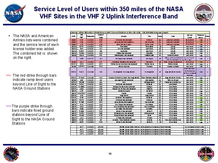
Service Level of Users within 350 miles of the NASA VHF Sites in the VHF 2 Uplink Interference Band Licences within 350 miles of NASA Soyuz VHF 2 Ground Stations in the 130. 1225 - 130. 225 MHz Frequency Band • The NASA and American Airlines lists were combined and the service level of each license holder was added. The combined list is shown on the right. R 0089 R 1036 R 0160 Call Sign KLV 5 KLC 9 KLJ 7 WXE 7 KIV 4 WMV 7 WHB 6 WQL 8 ASRI The red strike through bars indicate ramp level users beyond Line of Sight to the NASA Ground Stations Airport 130. 150 130. 125 130. 175 130. 125 130. 150 Code ONT SMF SNA TEB JFK LGA IAD PHL Airport City State User Ontario International Sacramento Metropolitan John Wayne Airport Teterboro JFK International Laguardia Dulles International Philadelphia International Ontario Sacramento Santa Anna Teterboro New York Chantilly Philadelphia CA CA CA NJ NY NY VA PA American Airlines ARINC British Airways Service Level Ramp level Low Level Low Level callsign KHP 9 is associated with a center freq of 131. 775 MHz fixed antenna, 663 m height Distance (Miles) Note < 199 < 350 < 199 < 295 < 199 1 1 1 1, 2 < 199 2 < 350 < 295 < 199 1 1 1 < 295 < 199 < 350 < 199 < 350 < 199 < 350 < 295 < 199 < 350 < 199 1 1 1 1, 2 2 1, 2 1 1 1, 2 1 1 KHP 9 131. 775 LAS Las Vegas International Las Vegas NV R 0290 RO 273 R 0369 KOL 2 KPD 2 WQTC 642 130. 150 130. 125 130. 200 CLT AVP TTN Charlotte/Douglas International Wilkes-Barre Scranton International Mercer County Charlotte Wilkes-Barre Trenton NC PA PA Duke Energy Corporation Delta Airlines Frontier Airlines RO 525 WKC 3 130. 200 FRG Farmingdale (on Long Island) Farmingdale NY Long Island Jet Center 130. 200 130. 125 130. 150 130. 125 130. 175 130. 176 130. 175 130. 125 130. 150 FOK LAX N/A OAK RDU PHX BUR FAT LGB OAK ONT SMF SAN SFO SJC EWR ABQ RNO ELP LBE EWR Francis S Gabreski Airport (on Long Island) Los Angeles International N/A Oakland International Raleigh-Durham International Phenix Sky Harbor International Burbank Airport Fresno Long Beach Oakland Metropolitan Ontario International Sacramento Metropolitan San Diego International San Francisco International San Jose International Newark International Albuquerque International Reno Canyon International El Paso International Latrobe / Westmorland County Newark International West Hampton Beach Los Angeles Killingssworth Oakland Raleigh Phoenix Burbank Fresno Long Beach Oakland Ontario Sacramento San Diego San Francisco San Jose Newark Albuquerque Reno El Paso Latrobe Newark NY CA CT CA NC AZ CA CA CA NJ NM NM TX PA NJ Long Island Jet Center Polar Air Cargo Shoreline Aviation Inc. Southwest US Airways US Airways US Airways US Airways Vee Neal Aviation Inc US Airways KGF 7 130. 150 CONUS Mobile Conus (100 units can be deployed as temporary fixed stations) FA 2 temporary fixed units 2 KGF 7 KUF 6 130. 175 130. 150 130. 175 CONUS Mobile Conus (100 units can be deployed as temporary fixed stations) FA 2 temporary fixed units 2 2 2 RO 525 WRB 66 R 0700 KAJ 4 RO 786 WOM 8 RO 828 WJV 6 RO 828 WHM 94 RO 934 KKG 9 R 0934 KLX 4 R 0934 WQET 787 RO 934 KLF 8 RO 934 KVH 4 R 0934 WPE 3 R 0934 WFM 9 R 0934 KRF 6 R 0934 KKX 6 R 0934 KBN 9 R 0934 WBQ 9 R 0934 WHP 3 R 0934 WRN 9 R 0934 KLY 2 R 0940 WXS 7 R 0975 KGQ 7 The purple strike through bars indicate fixed ground stations beyond Line of Sight to the NASA Ground Stations Frequency 36 Ramp level Low Level fixed location, 25 m elevation with a 8 m height antenna Low Level Low Level Low Level Low Level Low Level Low Level
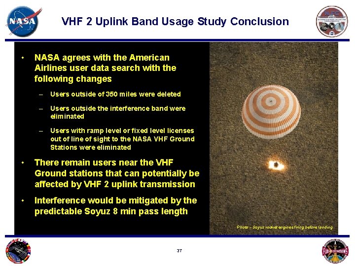
VHF 2 Uplink Band Usage Study Conclusion • NASA agrees with the American Airlines user data search with the following changes – Users outside of 350 miles were deleted – Users outside the interference band were eliminated – Users with ramp level or fixed level licenses out of line of sight to the NASA VHF Ground Stations were eliminated • There remain users near the VHF Ground stations that can potentially be affected by VHF 2 uplink transmission • Interference would be mitigated by the predictable Soyuz 8 min pass length Photo – Soyuz rocket engines firing before landing 37
Frequency Licenses in the NASA Soyuz VHF 2 Uplink Band • The following page contains the combined list of frequency licenses in the NASA Soyuz VHF 2 uplink band for the following distances: • 199 Mile 18, 000 foot direct Line of Sight radius • 295 Mile nominal aircraft descent path radius • 350 Mile long approach descent path radius Photo – Deep space from the ISS 38
Licenses within 350 miles in the VHF 2 Uplink Band • The table to the right is the remaining list of license holders under 350 miles from the NASA VHF 2 Ground Stations NOTES: Licenses within 350 miles of NASA Soyuz VHF 2 Ground Stations in the 130. 1225 - 130. 225 MHz Frequency Band * ASRI Frequency KGF 7 KUF 6 130. 150 130. 175 R 1036 R 0160 RO 273 R 0369 WQTC 642 RO 525 WRB 66 R 0700 KAJ 4 RO 786 WOM 8 RO 828 WJV 6 RO 828 WHM 94 RO 934 KKG 9 R 0934 KLX 4 R 0934 WQET 787 RO 934 KLF 8 RO 934 KVH 4 R 0934 WPE 3 R 0934 WFM 9 R 0934 KRF 6 R 0934 KKX 6 R 0934 KBN 9 R 0934 WBQ 9 R 0934 WHP 3 R 0934 WRN 9 R 0934 KLY 2 R 0940 WXS 7 R 0975 KGQ 7 * An altitude of 18, 000 foot altitude is required for line of sight at 199 miles. The listed frequencies are authorized for use between 10, 000 and 18, 000 feet. 1. From American Airlines provided frequency search list, 15 September 2016 Call Sign WXE 7 KIV 4 WMV 7 WHB 6 WQL 8 KPD 2 130. 150 130. 125 130. 175 130. 125 130. 150 130. 125 130. 200 130. 125 130. 150 130. 125 130. 175 130. 176 130. 175 130. 125 130. 150 Airport Code TEB JFK LGA IAD PHL AVP TTN FOK LAX N/A OAK RDU PHX BUR FAT LGB OAK ONT SMF SAN SFO SJC EWR ABQ RNO ELP LBE EWR CONUS Airport City State User Teterboro JFK International Laguardia Dulles International Philadelphia International Wilkes-Barre Scranton International Mercer County Francis S Gabreski Airport (on Long Island) Los Angeles International N/A Oakland International Raleigh-Durham International Phoenix Sky Harbor International Burbank Airport Fresno Long Beach Oakland Metropolitan Ontario International Sacramento Metropolitan San Diego International San Francisco International San Jose International Newark International Albuquerque International Reno Canyon International El Paso International Latrobe / Westmorland County Newark International Teterboro New York Chantilly Philadelphia Wilkes-Barre Trenton West Hampton Beach Los Angeles Killingssworth Oakland Raleigh Phoenix Burbank Fresno Long Beach Oakland Ontario Sacramento San Diego San Francisco San Jose Newark Albuquerque Reno El Paso Latrobe Newark NJ NY NY VA PA PA PA NY CA CT CA NC AZ CA CA CA NJ NM NM TX PA NJ ARINC British Airways Delta Airlines Frontier Airlines Long Island Jet Center Polar Air Cargo Shoreline Aviation Inc. Southwest US Airways US Airways US Airways US Airways Vee Neal Aviation Inc US Airways Mobile Conus (100 units can be deployed as temporary fixed stations) Service Distance Level Low Level Low Level Low Level Low Level Low Level Low Level Low Level (Miles) < 295 < 199 < 295 < 199 < 350 < 199 < 350 < 199 < 350 < 295 < 199 < 350 < 199 Note FA 2 temporary fixed units 2. From FCC ULS database search list in "Final EV 8 -15 -5018", United States (US) Spectrum Occupancy Assessment and Sharing Study of the Soyuz Very-High Frequency-2 (VHF-2) Voice Communication System , Brian Rhodes, JSC Engineering, Technology, and Science Contract ES-0129 -2311 -00007, page 6 39 1 1 1, 2 1 1 1 1 1, 2 2 1, 2 1 1 1, 2 1 1 2 2
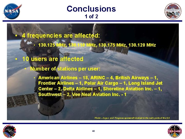
Conclusions 1 of 2 • 4 frequencies are affected: • 130. 125 MHz, 130. 150 MHz, 130. 175 MHz, 130. 120 MHz • 10 users are affected • Number of stations per user: • American Airlines – 18, ARINC – 4, British Airways – 1, Frontier Airlines – 1, Polar Air Cargo – 1, Long Island Jet Center – 2, Delta Airlines – 1, Shoreline Aviation Inc. – 1, Southwest – 2, Vee Neal Aviation Inc. - 1 Photo – Soyuz and Progress spacecraft docked to the nadir ports of the ISS 40
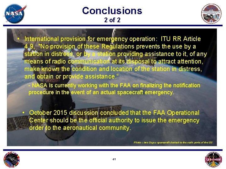
Conclusions 2 of 2 • International provision for emergency operation: ITU RR Article 4. 9, "No provision of these Regulations prevents the use by a station in distress, or by a station providing assistance to it, of any means of radio communication at its disposal to attract attention, make known the condition and location of the station in distress, and obtain or provide assistance. “ - NASA is currently working with the FAA on finalizing the notification procedure in the event of an actual spacecraft emergency. • October 2015 discussion concluded that the FAA Operational Center should be the official authority to issue the emergency order to the aeronautical community. Photo – two Soyuz spacecraft docked to the nadir ports of the ISS 41
Appendix Photo – long term earth exposure with lightning flashes 42
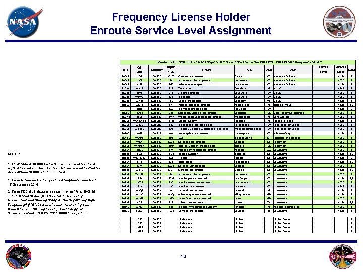
Frequency License Holder Enroute Service Level Assignment Licenses within 350 miles of NASA Soyuz VHF 2 Ground Stations in the 130. 1225 - 130. 225 MHz Frequency Band * NOTES: * An altitude of 18, 000 foot altitude is required for line of sight at 199 miles. The listed frequencies are authorized for use between 10, 000 and 18, 000 feet. 1. From American Airlines provided frequency search list, 15 September 2016 2. From FCC ULS database search list in "Final EV 8 -155018", United States (US) Spectrum Occupancy Assessment and Sharing Study of the Soyuz Very-High Frequency-2 (VHF-2) Voice Communication System , Brian Rhodes, JSC Engineering, Technology, and Science Contract ES-0129 -2311 -00007, page 6 Airport ASRI Call Sign Frequency R 0089 R 1036 R 0160 R 0290 RO 273 R 0369 RO 525 R 0700 RO 786 RO 828 RO 934 R 0934 R 0934 R 0934 R 0940 R 0975 KLV 5 KLC 9 KLJ 7 WXE 7 KIV 4 WMV 7 WHB 6 WQL 8 KHP 9 KOL 2 KPD 8 WQTC 462 WKC 3 WRB 66 KAJ 4 WOM 8 WJV 4 WHM 84 KKG 6 KLX 4 WQET 787 KLF 8 KVH 4 WPE 3 WFM 9 KRF 6 KKX 6 KBN 9 WBQ 9 WHP 3 WRN 9 KLY 2 WXS 7 KGQ 7 130. 150 130. 125 130. 200 130. 125 130. 150 130. 125 130. 175 130. 176 130. 175 130. 125 130. 150 Code ONT SMF SNA TEB JFK LGA IAD PHL LAS CLT AVP TTN FRG FOK LAX N/A OAK RDU PHX BUR FAT LGB OAK ONT SMF SAN SFO SJC EWR ABQ RNO ELP LBE EWR KGF 7 KUF 6 130. 150 130. 175 Airport City Ontario International Sacramento Metropolitan John Wayne Airport Teterboro JFK International Laguardia Dulles International Philadelphia International Las Vegas International Charlotte/Douglas International Wilkes-Barre Scranton International Mercer County Farmingdale (on Long Island) Francis S Gabreski Airport (on Long Island) Los Angeles International N/A Oakland International Raleigh-Durham International Phenix Sky Harbor International Burbank Airport Fresno Long Beach Oakland Metropolitan Ontario International Sacramento Metropolitan San Diego International San Francisco International San Jose International Newark International Albuquerque International Reno Canyon International El Paso International Latrobe / Westmorland County Newark International Ontario Sacramento Santa Anna Teterboro New York Chantilly Philadelphia Las Vegas Charlotte Wilkes-Barre Trenton Farmingdale West Hampton Beach Los Angeles Killingssworth Oakland Raleigh Phoenix Burbank Fresno Long Beach Oakland Ontario Sacramento San Diego San Francisco San Jose Newark Albuquerque Reno El Paso Latrobe Newark Mobile user Mobile 43 State CA CA CA NJ NY NY VA PA NV NC PA PA NY NY CA CT CA NC AZ CA CA CA NJ NM NM TX PA NJ Service Level User American Airlines ARINC British Airways Duke Energy Corporation Delta Airlines Frontier Airlines Long Island Jet Center Polar Air Cargo Shoreline Aviation Inc. Southwest US Airways US Airways US Airways US Airways Vee Neal Aviation Inc US Airways Mobile Conus Distance Note (Miles) < 199 < 350 < 199 < 295 < 199 < 350 < 295 < 199 < 350 < 199 < 350 < 199 < 350 < 295 < 199 < 350 < 199 1 1 1 1, 2 2 1 1 1, 2 2 1, 2 1 1 1, 2 1 1 2 2
Background (1 of 2) • VHF 2 frequency pair is the only space-to-ground voice channels between the Soyuz and capable ground stations. • The Soyuz will be used exclusively for ISS crew transport until at least 2018 • The Soyuz will continue to provide ISS crew transport until at least 2024 44
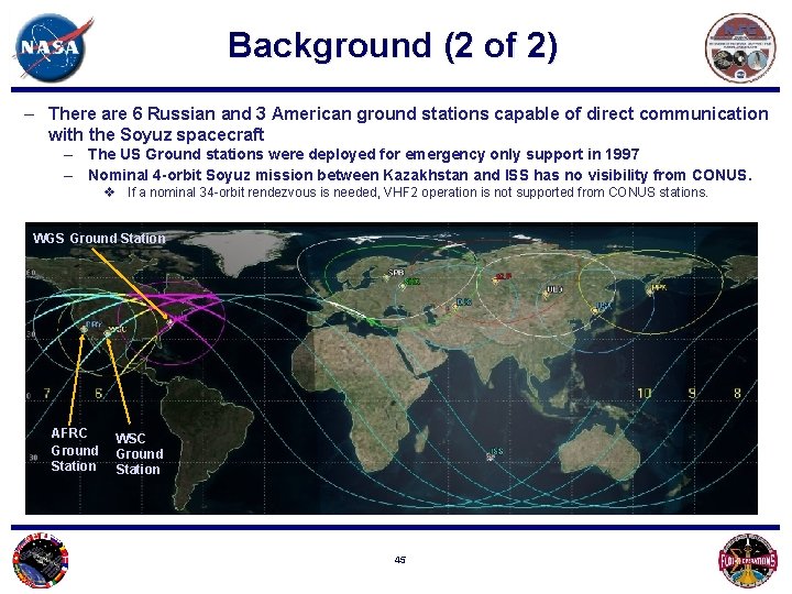
Background (2 of 2) – There are 6 Russian and 3 American ground stations capable of direct communication with the Soyuz spacecraft – The US Ground stations were deployed for emergency only support in 1997 – Nominal 4 -orbit Soyuz mission between Kazakhstan and ISS has no visibility from CONUS. v If a nominal 34 -orbit rendezvous is needed, VHF 2 operation is not supported from CONUS stations. WGS Ground Station AFRC Ground Station WSC Ground Station 45
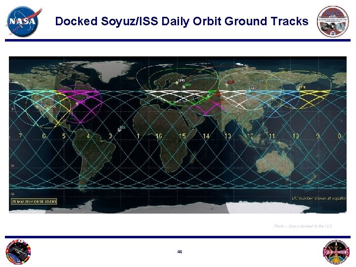
Docked Soyuz/ISS Daily Orbit Ground Tracks Photo – Soyuz docked to the ISS 46
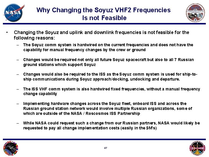
Why Changing the Soyuz VHF 2 Frequencies Is not Feasible • Changing the Soyuz and uplink and downlink frequencies is not feasible for the following reasons: – The Soyuz comm system is hardwired on the current frequencies and does not have the capability for manual frequency changes by the crew or ground – Changes would be required not only all future Soyuz spacecraft but also to all 7 Russian ground stations which support Soyuz – Changes would also be required to the ISS as the Soyuz comm system is used for ship-toship communications during Soyuz approach/docking, undocking and departure. – The ISS VHF comm system is also hardwired fixed frequencies, without a manual frequency change capability – Implementing hardware changes across the Soyuz fleet, onboard ISS and across the Russian ground station network would involve multiple Russian organizations, some of which are outside of the NASA / Roscosmos ISS Partnership – While NASA could request such a change from our Russian partners, NASA would likely be requested to pay all change implementation costs (easily in the $M’s) 47
DFRC VHF 2 INTERFERENCE TESTING REV 4 Michael Yettaw Darren Mills 17 Nov 03 48
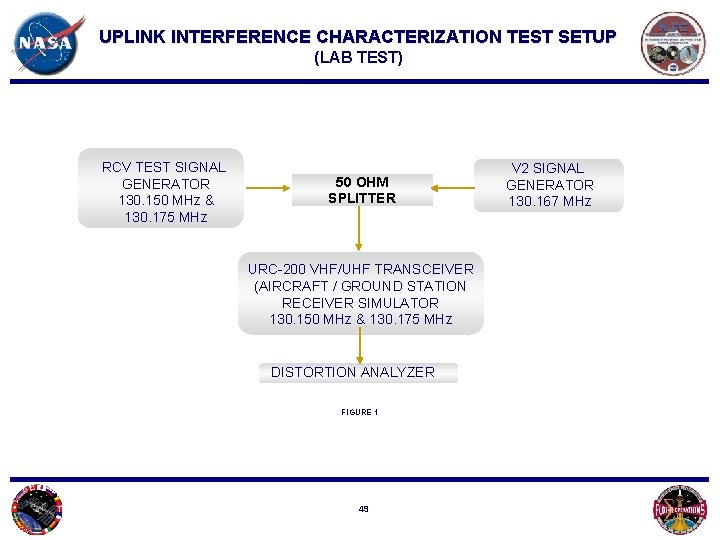
UPLINK INTERFERENCE CHARACTERIZATION TEST SETUP (LAB TEST) RCV TEST SIGNAL GENERATOR 130. 150 MHz & 130. 175 MHz 50 OHM SPLITTER URC-200 VHF/UHF TRANSCEIVER (AIRCRAFT / GROUND STATION RECEIVER SIMULATOR 130. 150 MHz & 130. 175 MHz DISTORTION ANALYZER FIGURE 1 49 V 2 SIGNAL GENERATOR 130. 167 MHz
VHF 2 UPLINK INTERFERENCE CHARACTERIZATION TEST RESULTS • VHF 2 Interference induced Squelch break occurred on the 130. 150 frequency at – 80 d. Bm. • The signal level of the VHF 2 Ground Station antenna drops to a minimum of approximately 30 d. B at 90 degrees off axis. • Interference is induced when the VHF 2 Ground Station uplink Transmitter signal strength rises to within 25 d. B of the 130. 175 and 15 d. B of the 130. 150 Frequency. • Interference can render the frequencies unusable (>10% distortion) if the VHF 2 Ground Station transmitter signal strength rises to within 20 d. B of the 130. 175 frequency and 5 d. B of the 130. 150 frequency. • Commercial aviation routes come within 15 miles of the VHF Ground Station exposing them to a signal level as high – 34 d. Bm if directly in the antenna pattern. • VHF 2 induced receiver distortion was detected when operating on frequencies from 130. 1225 to 130. 225 on the URC test Receiver ( - 44. 5 KHz to + 55 KHz interference bandwidth ). The test receiver 12. 5 KHz tuning increments do not correspond to the actual receiver band reject capabilities. 50
UPLINK TEST SUMMARY CONCLUSIONS • The VHF 2 Ground Station can potentially interfere with the Airline frequencies. The interference can range from mild to severe depending on signal strength ratio. • Interference can render the Airline frequencies unusable (>10% distortion) if the VHF 2 Ground Station transmitter signal strength rises to within approximately 15 d. B of the Airline Frequency. • Interference can occur at 90 degrees off axis to the VHF 2 Ground Station antenna if the Aircraft is close enough. • The VHF 2 ground station 130. 167 uplink can potentially interfere with a receiver operating on frequencies from 130. 1225 to 139. 225 ( - 44. 5 KHz to + 55 KHz interference bandwidth ) • Ground station line of sight extends out to 260 miles (for an aircraft at an altitude of 45, 000 feet). 51
Soyuz VHF 2 Downlink Interference Analysis Photo – Sunset from ISS 52
Downlink Interference Analysis Soyuz Docked to the ISS Number must be positive to be detected by the Aircraft or Ground receiver 53
Downlink Interference Analysis Soyuz Free-Flying to the ISS Number must be positive to be detected by the receiver 54
Soyuz VHF 2 Downlink Performance to ATC AM Receiver The Soyuz signal is 19 d. B to 54 d. B below the squelch threshold of the typical ATC or Aircraft AM receiver 55
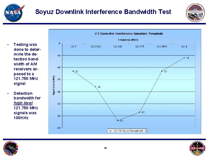
Soyuz Downlink Interference Bandwidth Test • Testing was done to determine the detection bandwidth of AM receivers exposed to a 121. 750 MHz signal • Detection bandwidth for high level 121. 750 MHz signals was 100 KHz 56
Soyuz Downlink Bandwidth Interference Potential Analysis • 121. 750 MHz can be detected by a receiver from 121. 7 MHz to 121. 8 MHz which yields a detection bandwidth of 100 k. Hz. • Test data shows a large out of band signal -12 to -25 d. Bm) is required to cause receiver degradation based on interference ( • No off frequency users were found in the detection bandwidth in the U. S. (121. 751 MHz 121. 8 MHz or 121. 7 MHz - 121. 749 MHz) • Users were found on the 121. 750 MHz frequency 57
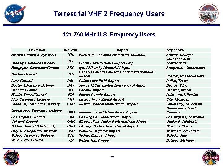
Terrestrial VHF 2 Frequency Users 121. 750 MHz U. S. Frequency Users Utilization Atlanta Ground (Rwys 9/27) AP Code Airport ATL Hartsfield - Jackson Atlanta International BDL Bradley Clearance Delivery Bridgeport Clearance/Ground BDR Boston Ground BOS Love Ground Dayton Clearance Delivery Decatur Ground Flagler Tower/Ground Flint Clearance Delivery Green Bay Clearance Delivery DAL DAY DEC FIN FNT GRB Bradley International Airport City Igor I Sikorsky Memorial Airport General Edward Lawrence Logan International Airport Dallas Love Field Airport James M Cox Dayton International Airpor Decatur Airport Flagler County Airport Bishop International Airport Austin Straubel International Airport GSO LAX OAK ORD OSH TOL YIP Piedmont Triad International Airport Los Angeles International Airpor Metropolitan Oakland International Airport Chicago O'Hare International Airport Wittman Regional Airport Toledo Express Airport Willow Run Airport Greensboro Clearance Delivery Los Angeles Ground Oakland Ground O'Hare Ground (Outbound) Rwy 9/27 Departure Monitor Toledo Clearance Delivery Willow Run Ground 58 City / State Atlanta, Georgia Windsor Locks, Connecticut Bridgeport, Connecticut Boston, Massachusetts Dallas, Texas Dayton, Ohio Decatur, Illinois Palm Coast, Florida City, Michigan Green Bay, Wisconsin Greensboro, North Carolina Los Angeles, California Oakland, California Chicago, Illinois Oshkosh, Wisconsin Toledo, Ohio Detroit, Michigan
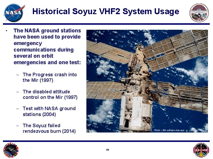
Historical Soyuz VHF 2 System Usage • The NASA ground stations have been used to provide emergency communications during several on orbit emergencies and one test: – The Progress crash into the Mir (1997) – The disabled attitude control on the Mir (1997) – Test with NASA ground stations (2004) – The Soyuz failed rendezvous burn (2014) Photo – Mir collision damage 59
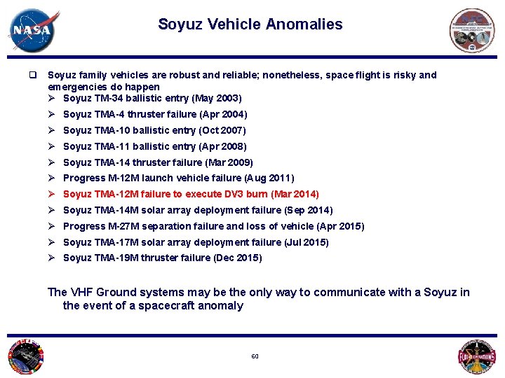
Soyuz Vehicle Anomalies q Soyuz family vehicles are robust and reliable; nonetheless, space flight is risky and emergencies do happen Ø Soyuz TM-34 ballistic entry (May 2003) Ø Soyuz TMA-4 thruster failure (Apr 2004) Ø Soyuz TMA-10 ballistic entry (Oct 2007) Ø Soyuz TMA-11 ballistic entry (Apr 2008) Ø Soyuz TMA-14 thruster failure (Mar 2009) Ø Progress M-12 M launch vehicle failure (Aug 2011) Ø Soyuz TMA-12 M failure to execute DV 3 burn (Mar 2014) Ø Soyuz TMA-14 M solar array deployment failure (Sep 2014) Ø Progress M-27 M separation failure and loss of vehicle (Apr 2015) Ø Soyuz TMA-17 M solar array deployment failure (Jul 2015) Ø Soyuz TMA-19 M thruster failure (Dec 2015) The VHF Ground systems may be the only way to communicate with a Soyuz in the event of a spacecraft anomaly 60
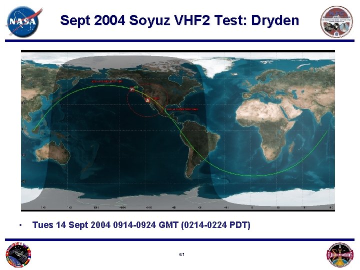
Sept 2004 Soyuz VHF 2 Test: Dryden • Tues 14 Sept 2004 0914 -0924 GMT (0214 -0224 PDT) 61
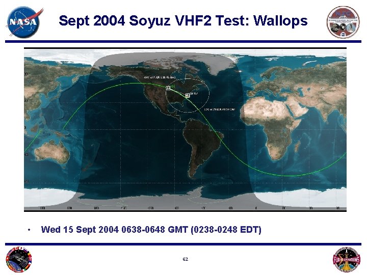
Sept 2004 Soyuz VHF 2 Test: Wallops • Wed 15 Sept 2004 0638 -0648 GMT (0238 -0248 EDT) 62
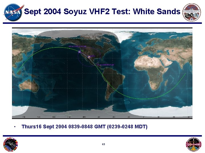
Sept 2004 Soyuz VHF 2 Test: White Sands • Thurs 16 Sept 2004 0839 -0848 GMT (0239 -0248 MDT) 63
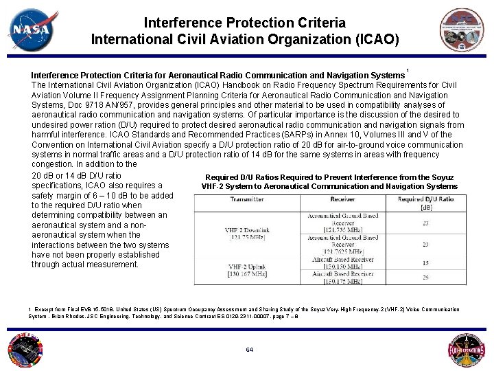
Interference Protection Criteria International Civil Aviation Organization (ICAO) 1 Interference Protection Criteria for Aeronautical Radio Communication and Navigation Systems The International Civil Aviation Organization (ICAO) Handbook on Radio Frequency Spectrum Requirements for Civil Aviation Volume II Frequency Assignment Planning Criteria for Aeronautical Radio Communication and Navigation Systems, Doc 9718 AN/957, provides general principles and other material to be used in compatibility analyses of aeronautical radio communication and navigation systems. Of particular importance is the discussion of the desired to undesired power ration (D/U) required to protect desired aeronautical radio communication and navigation signals from harmful interference. ICAO Standards and Recommended Practices (SARPs) in Annex 10, Volumes III and V of the Convention on International Civil Aviation specify a D/U protection ratio of 20 d. B for air-to-ground voice communication systems in normal traffic areas and a D/U protection ratio of 14 d. B for the same systems in areas with frequency congestion. In addition to the 20 d. B or 14 d. B D/U ratio Required D/U Ratios Required to Prevent Interference from the Soyuz specifications, ICAO also requires a VHF-2 System to Aeronautical Communication and Navigation Systems safety margin of 6 – 10 d. B to be added to the required D/U ratio when determining compatibility between an aeronautical system and a nonaeronautical system when the interactions between the two systems have not been properly established through actual measurement. 1 Excerpt from Final EV 8 -15 -5018, United States (US) Spectrum Occupancy Assessment and Sharing Study of the Soyuz Very-High Frequency-2 (VHF-2) Voice Communication System , Brian Rhodes, JSC Engineering, Technology, and Science Contract ES-0129 -2311 -00007, page 7 – 8 64
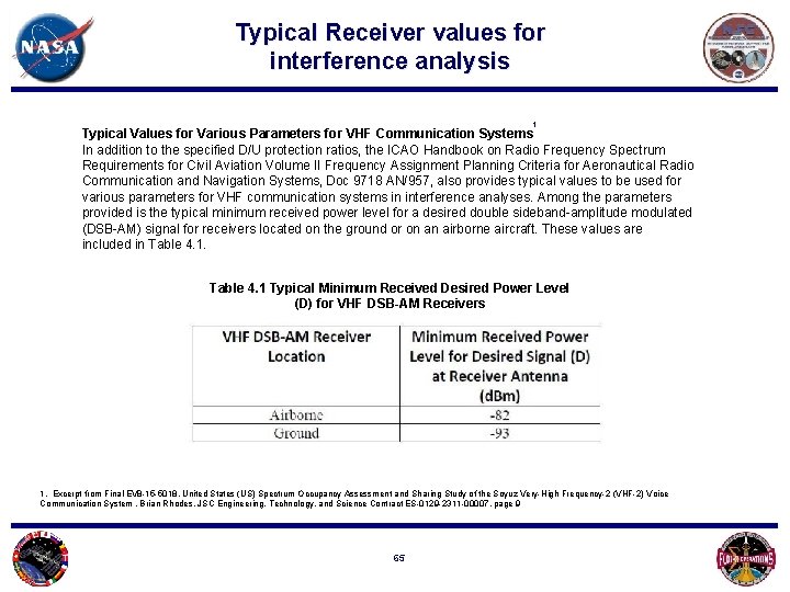
Typical Receiver values for interference analysis 1 Typical Values for Various Parameters for VHF Communication Systems In addition to the specified D/U protection ratios, the ICAO Handbook on Radio Frequency Spectrum Requirements for Civil Aviation Volume II Frequency Assignment Planning Criteria for Aeronautical Radio Communication and Navigation Systems, Doc 9718 AN/957, also provides typical values to be used for various parameters for VHF communication systems in interference analyses. Among the parameters provided is the typical minimum received power level for a desired double sideband-amplitude modulated (DSB-AM) signal for receivers located on the ground or on an airborne aircraft. These values are included in Table 4. 1 Typical Minimum Received Desired Power Level (D) for VHF DSB-AM Receivers 1. Excerpt from Final EV 8 -15 -5018, United States (US) Spectrum Occupancy Assessment and Sharing Study of the Soyuz Very-High Frequency-2 (VHF-2) Voice Communication System , Brian Rhodes, JSC Engineering, Technology, and Science Contract ES-0129 -2311 -00007, page 9 65
Descent Profile Data Figure 1 taken from: Evaluation of Continuous Descent Approach as a Standard Terminal Airspace Operation. Joseph Post Office of Systems analysis, FAA_http: //atmseminar. org/seminar. Content/seminar 9/papers/62 -Cao-Final-Paper-4 -411. pdf 66
Descent Profile Data 67