Chapter 9 VOR VHF Omnidirectional Range VOR stands


 Here is an HSI. The compass card is slaved to")
 The RMI displays both VOR and ADF (automatic direction finder)")

 Area Navigation Since the VOR’s have a relatively short range, using them to")


- Slides: 26
Chapter 9 VOR VHF Omnidirectional Range
VOR stands for VHF Omnidirectional Range. A VOR is a radio beacon that transmits a signal that represents the 360º of the compass.
VOR Ground Station Above is a VORTAC station. VORTAC stands for VOR + TACAN Stands for Tactical Air Navigation and it includes DME is Distance Measuring Equipment, and it’ll tell you how far your are from the station. The “counterpoise” is the base of the station and provides grounding of the station.
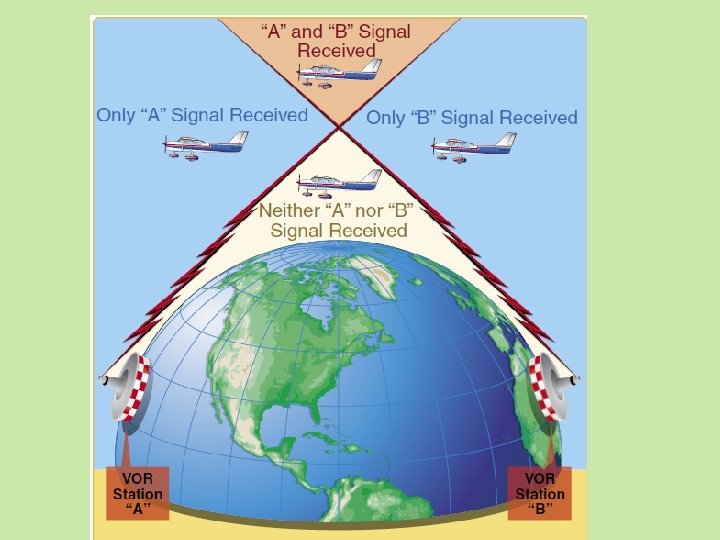
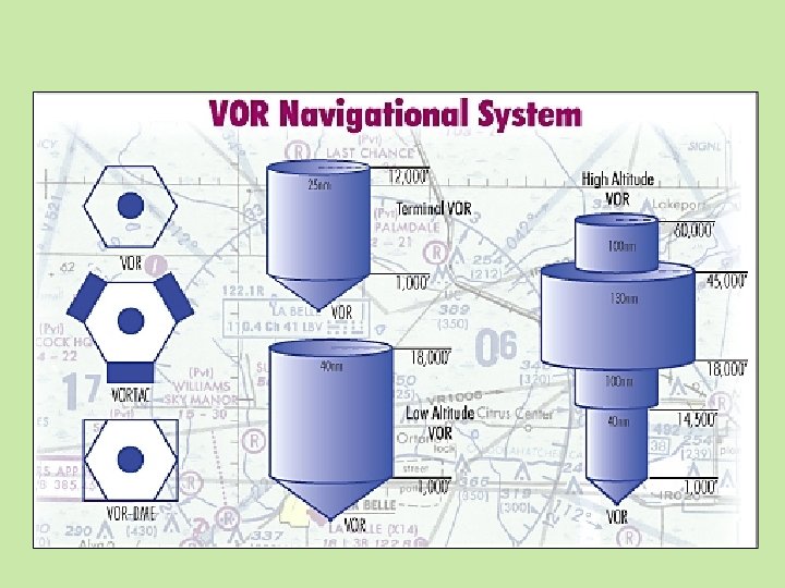
VOR Service Coverage VOR broadcasts from 108. 000 -117. 950 MHZ. It’s operational service volume is up to 130 NM from the station (upper right). There are 3 types of VOR stations (lower right).
AFD Airport / Facility Directory
VOR Phases The VOR signal is comprised of a Reference Phase and a Variable Phase. The Reference Phase is broadcast in all directions. The Variable Phase is a rotating beam. The difference of phase between the Reference Phase and the Variable Phase is used by the VOR receiver in the airplane to calculate the bearing from the station. Textbook page 59
VOR Signal Structure Textbook page 60
VOR 2 Signals Here is the VOR signal as it appears to the receiver. The carrier rises and falls in strength (AM). The signal is at max strength when the rotating beam is pointed directly at the airplane shown by the blue arrow. The red arrow shows the highest frequency of the subcarrier which occurs at N. The receiver compares the 2 signals by measuring the phase of each signal then calculates the difference as a magnetic course from the VOR. Textbook page 61
VOR Broadcasts 2 Signals The Reference and Variable Phase signals from the VOR cannot be mixed during transmission. To keep them apart, the Reference Phase is placed on a “subcarrier”. At resting frequency of 9960 HZ, the subcarrier is shifted up and down in frequency by the Reference Phase 30 x/sec. (FM) The illustration shows the subcarrier increases in frequency going positive and decreases frequency going negative. N is indicated at max positive shown by the left arrow and is at 10, 440 HZ. S is indicated at max negative shown by the right arrow and is at 9480 HZ.
VOR Block Diagram Textbook page 62
VOR Navigation Textbook page 63
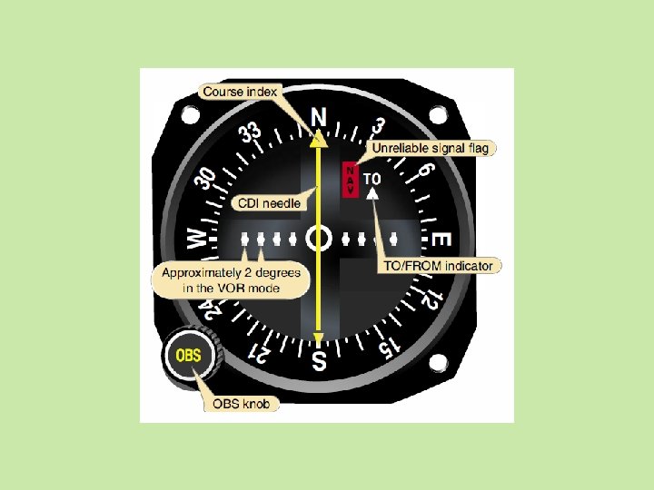
VOR Indicator Here is a VOR Indicator used in General Aviation. The VOR course is selected by turning the OBS (Omni Bearing Selector) knob to the desired course. The Course Deviation Indicator (CDI) displays steering commands. Textbook page 63
Horizontal Situation Indicator (HSI) Here is an HSI. The compass card is slaved to the compass system and shows the aircraft’s heading automatically. The course is selected by a knob located elsewhere and is displayed by digitally in the upper right corner and by the course needle, here it is 20°. The deviation bar shows that we are off course to the right. Textbook page 64
Radio Magnetic Indicator (RMI) The RMI displays both VOR and ADF (automatic direction finder) information. The compass card is slaved to the compass system. Textbook page 64
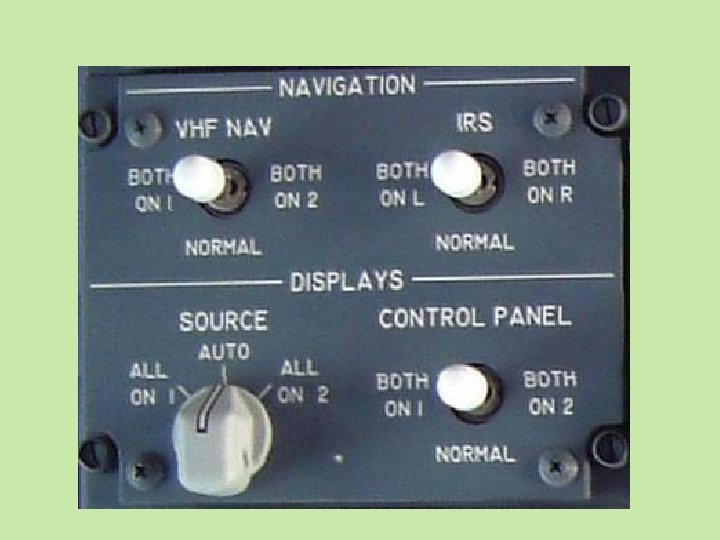
Nav Control-Display Textbook page 65
(RNAV) Area Navigation Since the VOR’s have a relatively short range, using them to navigate would cause “doglegs”, flying a “connect-thedots” path. RNAV, or area navigation solves this problem by referencing VOR stations and computing a straight-line path.
Review Q&A Chapter 9 VOR 9. 1 What is the name of a combined VOR and TACAN navigational station? Answer: VORTAC 9. 2 What problem of early radio navigation did VOR overcome? Answer: It is immune from electrical interference. 9. 3 VOR waves travel ______. Answer: 130 nautical miles. 9. 4 Name the 2 major components of a VOR signal. Answer: Reference and Variable 9. 5 The reference phase broadcasts in what direction? Answer: All directions 9. 6 The variable phase rotates ___ times per second. Answer: 30 9. 7 What happens when the variable phase moves though magnetic north (0°)? Answer: The reference phase goes to it’s max positive and the subcarrier rises to 10, 440 HZ. 9. 8 How does the VOR receiver know its bearing from the VOR station? Answer: It compares the 2 signals and uses the difference to calculate bearing to the station. 9. 9 Besides fixed and variable phase signals, what other information is broadcast by a VOR station? Answer: Station ID in Morse Code and in voice. 9. 10 What is the purpose of the course deviation indicator (CDI) on a VOR receiver? Answer: To display steering information to the course.
FAA. GOV AIM Aviation