Solar Telematics System ECE 477 Design Review Team


 • Drive an")

 • Integrated")
 •")
 • 2 MB •")


- Slides: 55
Solar Telematics System ECE 477 Design Review, Team 8, Spring 2012 Paste a photo of team members here, annotated with names of team members. Craig Lechlitner, Dan Ehrman, Clayton Dickemann, Brian Kelley
Outline • Project overview • Project-specific success criteria • Block diagram • Component selection rationale • Packaging design • Schematic and theory of operation • PCB layout • Software design/development status • Project completion timeline • Questions / discussion
Project Overview • Touchscreen driver display for • • • PSR's next vehicle: Navitas Communicates with other on-board systems Collects and displays continuous vehicle diagnostics Controls various essential vehicle functions Relays data to the sidelines for monitoring and analysis Testing in existing car: Celeritas
Project-Specific Success Criteria 1. An ability to track vehicle location using GPS. 2. An ability to send and receive CAN messages from and to other systems in the car. 3. An ability to display graphics on the LCD display. 4. An ability to respond to user input from a touchscreen. 5. An ability to store and load data to and from non- volatile memory.
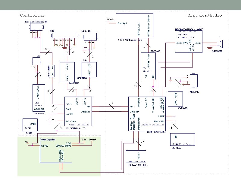
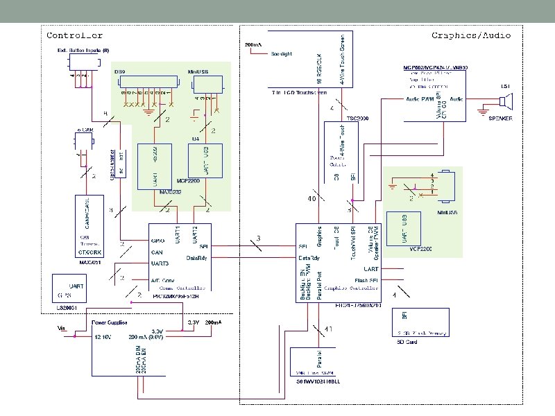
Block Diagram
Component Selection Rationale Implementation Requirements • Must be passed on to PSR team • Must talk to other on-board systems using CAN • Must utilize existing development tools • Must fit in a compact solar car • Must be easily usable/visible by the driver
Component Selection Rationale Technical requirements • Graphics processing (images and text) • Drive an 800 x 480 LCD @ >= 4 Hz (min. ) • Read touchscreen input • Read images and sound from SD card • Generate sound • Send/receive CAN data to/from other systems • Receive GPS data • Send/receive data between two micros
Component Selection - LCD Hantronix HDA 700 L-1 • 7" 800 x 480 color TFT • 18 -bit RGB input • Brightness: 500 nit • Contrast ratio: 250: 1 • X and Y analog touchscreen output TSC 2000 • Converts analog X and Y to digital • Sends touch data over SPI
Component Selection - Graphics PIC 24 FJ 256 DA 210 (100 -pin) • Integrated GFX module • Character generation • Rectangle copy • Image deflator • Direct RGB output to LCD • • • display 16 -bit color 96 K SRAM PMP for external SRAM 4 UART, 3 SPI 8 MHz internal oscillator
Component Selection - Communication PIC 32 MX 795 F 512 H (64 -pin) • 2 CAN • 3 SPI • 6 UART • Using with external 10 MHz oscillator
Component Selection - Other IS 61 WV 102416 BLL (SRAM) • 2 MB • 10 ns • 3. 3 V LS 20031 (GPS) • 5 Hz • UART • Internal antenna • 3. 3 V
Packaging Design
Schematic and Theory of Operation
Power Supplies
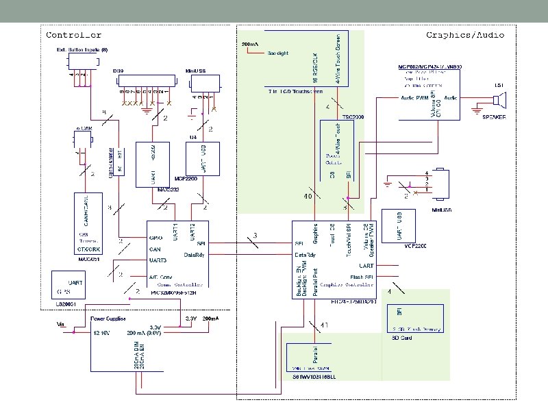
TS/LCD Interface
SRAM
SD Card
Graphics Microcontroller
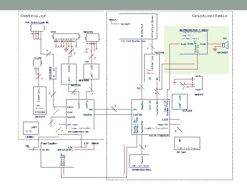
Audio
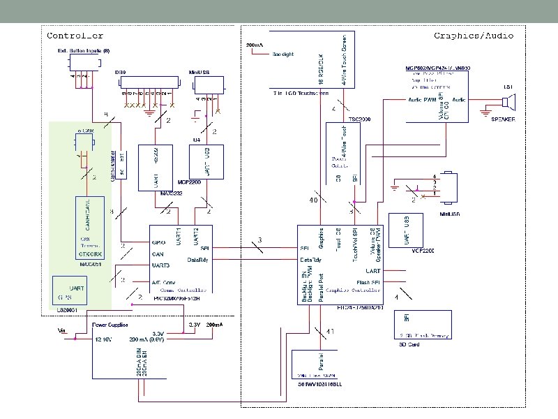
GPS
CAN
UART – RS 232 Transceiver
UART – MCP 2200
PIC 32 Microcontroller
Misc. – External Switches
Misc. – Car Battery Enable/Disable
Misc. – ATD Circuitry
Misc. – Decoupling Caps, Oscillator, Programming Header, Debug LEDs
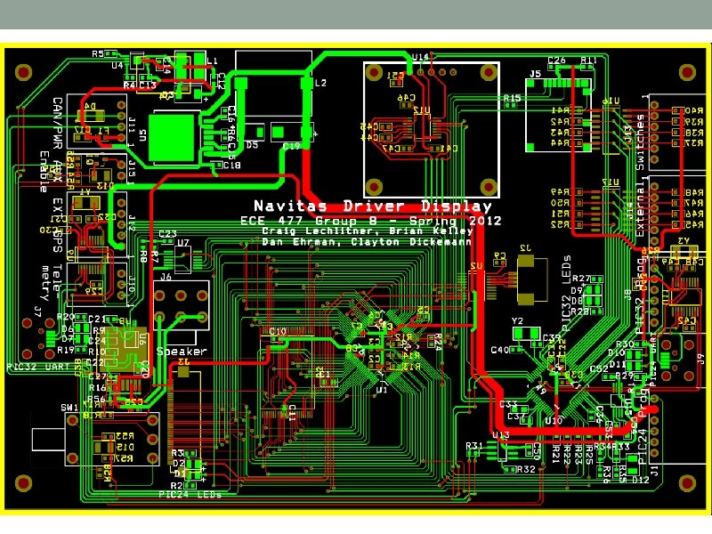
PCB Layout • 6½” x 4¼” to match size of LCD • Mounting holes match those on LCD. • Most traces 12 mil • Power is much larger (>50 mil) • Connections to graphics controller are 8 mil to fit footprint. • Line up ribbon cable connectors to match LCD • Place commonly used connectors away from board edges so all wires exit through hole in rear of housing. • Place infrequently used connectors next to edge to save board space
PCB Layout – Top Copper
PCB Layout – Bottom Copper
PCB Layout – Power Supplies • Minimize length of high current traces • Use wider traces for 3. 3 V supply (>50 mil for 3 A) • Minimize vias between inductor, diode, switch, and capacitor. • Place fuse close to Vin.
PCB Layout – Power Supplies
PCB Layout - Microcontrollers • Place decoupling capacitors on opposite side from microcontrollers, as close as possible to Vdd pins. • Place crystal oscillator and capacitors as close as possible to PIC 32 and MCP 2200. • Keep high frequency signals (96 MHz) short. • Graphics controller • SRAM • LCD connector • Place vias on all data lines for probing.
PCB Layout - Microcontrollers PIC 24 Decoupling Capacitors PIC 32 Decoupling Capacitors
PCB Layout – Crystal Oscillator
Software Design and Development Status
Software Design – Key Points Higher-level • Code split between graphics and communication • MVC model of GUI development Low-level • Interrupt-driven • Existing PSR CAN library • Microchip Disk Drive library (SD card) • Custom audio and graphics libraries
Communication The Car Wireless Modem CAN Processing Graphics SD Storage Framework SD Card Telemetry Processing Application Logic Audio Processing Communications Control Widget Framework Touch Processing Speaker System LCD Data Registry (Communication) GPS Processing Data Registry (Graphics) Graphics Processing High level Low level
Communication The Car Wireless Modem CAN Processing Graphics SD Storage Framework SD Card Telemetry Processing Application Logic Audio Processing Communications Control Widget Framework Touch Processing Speaker System LCD Data Registry (Communication) GPS Processing Data Registry (Graphics) Graphics Processing High level Low level
Communication The Car Wireless Modem CAN Processing Graphics SD Storage Framework SD Card Telemetry Processing Application Logic Audio Processing Communications Control Widget Framework Touch Processing Speaker System LCD Data Registry (Communication) GPS Processing Data Registry (Graphics) Graphics Processing High level Low level
Communication The Car Wireless Modem CAN Processing Graphics SD Storage Framework SD Card Telemetry Processing Application Logic Audio Processing Communications Control Widget Framework Touch Processing Speaker System LCD Data Registry (Communication) GPS Processing Data Registry (Graphics) Graphics Processing High level Low level
Communication The Car Wireless Modem CAN Processing Graphics SD Storage Framework SD Card Telemetry Processing Application Logic Audio Processing Communications Control Widget Framework Touch Processing Speaker System LCD Data Registry (Communication) GPS Processing Data Registry (Graphics) Graphics Processing High level Low level
Communication The Car Wireless Modem CAN Processing Graphics SD Storage Framework SD Card Telemetry Processing Application Logic Audio Processing Communications Control Widget Framework Touch Processing Speaker System LCD Data Registry (Communication) GPS Processing Data Registry (Graphics) Graphics Processing High level Low level
Project Timeline Week Task Hardware Finalize PCB layout PCB population and testing Software Graphics processing dev/test GPS processing dev/test Touch processing dev/test Telemetry dev/test Communications control dev/test Widget integration Application logic dev/test CAN simulation System-wide simulation General debugging Packaging Documentation Software design narrative Patent liability analysis Reliability and safety analysis Ethical and environmental impact analysis User manual 8 9 10 11 12 13 14 15 16
Questions/Discussion