
ECE 477 Design Review Group 05 IMS Fall





- Slides: 40
ECE 477 Design Review Group 05 (IMS) Fall 2005 Roy Jeffry Kye. Yoon Wei Foong Paste a photo of team members here, annotated with names of team members.
Outline • • • Project overview Project-specific success criteria Block diagram Component selection rationale Packaging design Schematic and theory of operation PCB layout Software design/development status Project completion timeline Questions / discussion
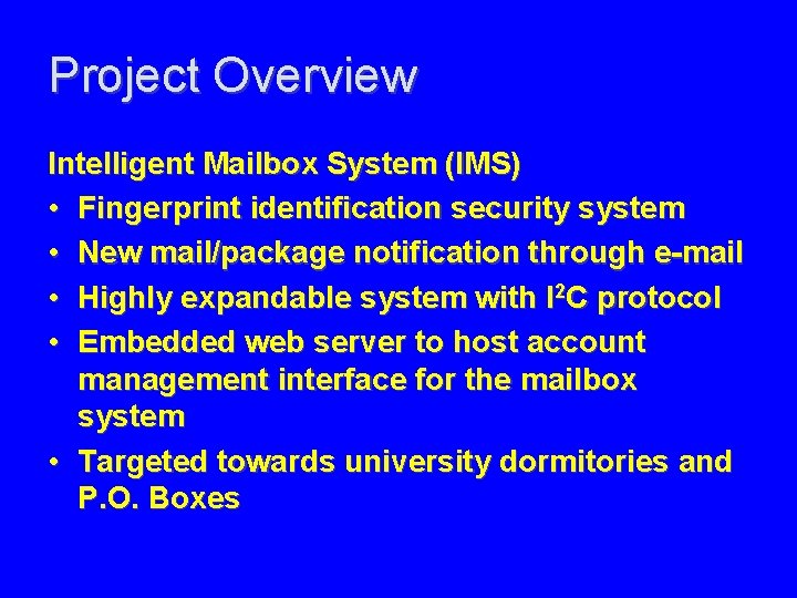
Project Overview Intelligent Mailbox System (IMS) • Fingerprint identification security system • New mail/package notification through e-mail • Highly expandable system with I 2 C protocol • Embedded web server to host account management interface for the mailbox system • Targeted towards university dormitories and P. O. Boxes
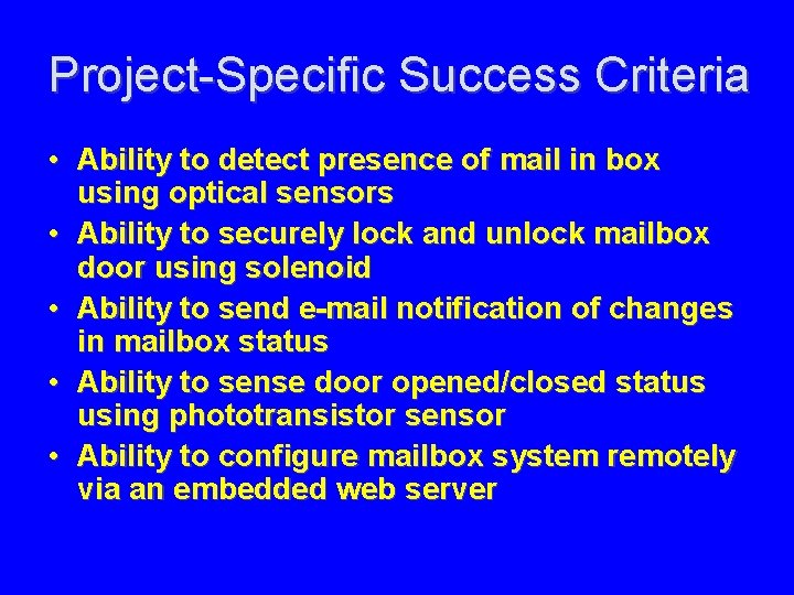
Project-Specific Success Criteria • Ability to detect presence of mail in box using optical sensors • Ability to securely lock and unlock mailbox door using solenoid • Ability to send e-mail notification of changes in mailbox status • Ability to sense door opened/closed status using phototransistor sensor • Ability to configure mailbox system remotely via an embedded web server
Block Diagram
Component Selection Rationale Main Microcontroller (MC 9 S 12 NE 64) – MC 9 S 12 NE 64 (70 GPIO) • Ethernet interface, I 2 C and other peripherals • 8 KB RAM, 64 KB of Flash (Operating voltage: 3. 3 V) • Familiarity with peripherals and instructions set – RCM 3000 (56 GPIO) • • • Similar peripherals as MC 9 S 12 NE 64 512 KB RAM, 512 KB of Flash (Operating voltage: 3. 3 V) Tricky header orientation Multi-threaded code execution Buggy compiler
Component Selection Rationale External Microcontroller (MC 9 S 08 GT 32) – MC 9 S 08 GT 32 (48 pins) 17 pins required • • • I 2 C and other peripherals Operating voltage (1. 8 -3. 6 V) Familiarity with peripherals and instructions set – PIC 16 F 819 (18 pins) • Similar peripherals as MC 9 S 08 GT 32 • Operating voltage (2 -5. 5 V) • Less application notes available
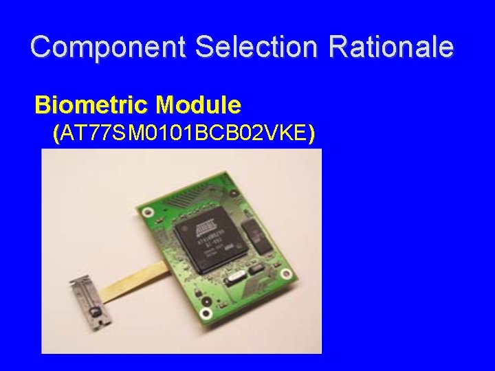
Component Selection Rationale Biometric Module (AT 77 SM 0101 BCB 02 VKE ) ( – AT 77 SM 0101 BCB 02 VKE • • • Includes enrollment, authentication software Finger scanner included SPI interface – MCF 5249 • Have to purchase enrollment, authentication software • Finger scanner not included • More expensive than AT 77 SM 0101 BCB 02 VKE
Component Selection Rationale Biometric Module (AT 77 SM 0101 BCB 02 VKE)
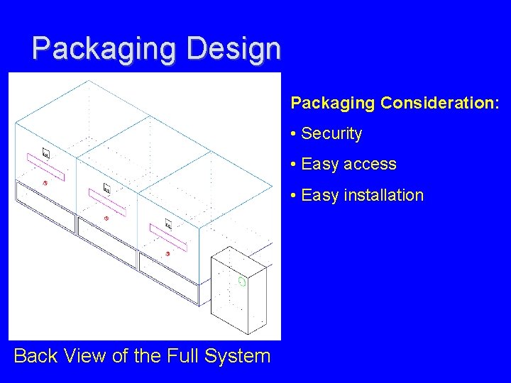
Packaging Design Packaging Consideration: • Security • Easy access • Easy installation Back View of the Full System
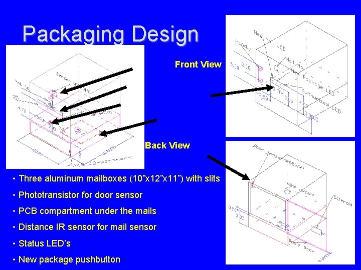
Packaging Design Front View Back View • Three aluminum mailboxes (10”x 12”x 11”) with slits • Phototransistor for door sensor • PCB compartment under the mails • Distance IR sensor for mail sensor • Status LED’s • New package pushbutton
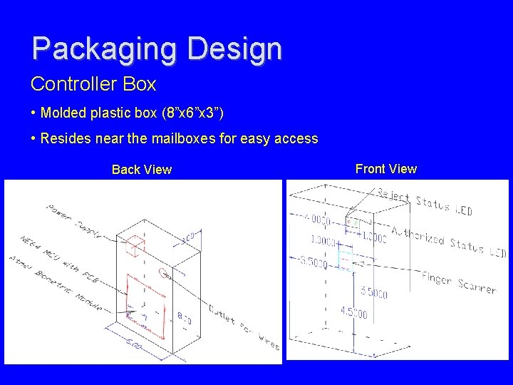
Packaging Design Controller Box • Molded plastic box (8”x 6”x 3”) • Resides near the mailboxes for easy access Back View Front View
Schematic/Theory of Operation How does the IMS work?
Schematic/Theory of Operation
Schematic/Theory of Operation
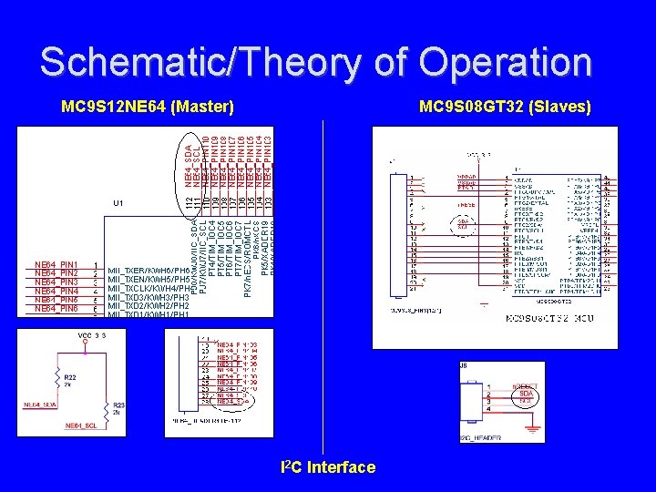
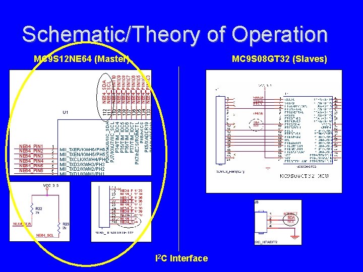
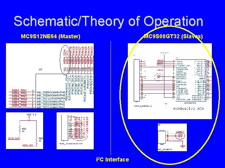
Schematic/Theory of Operation MC 9 S 12 NE 64 (Master) MC 9 S 08 GT 32 (Slaves) I 2 C Interface
Schematic/Theory of Operation MC 9 S 12 NE 64 (Master) MC 9 S 08 GT 32 (Slaves) I 2 C Interface
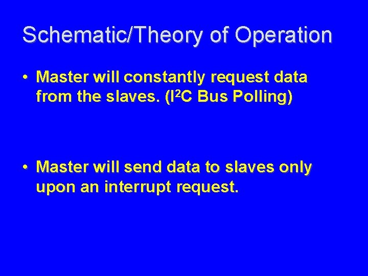
Schematic/Theory of Operation • Master will constantly request data from the slaves. (I 2 C Bus Polling) • Master will send data to slaves only upon an interrupt request.
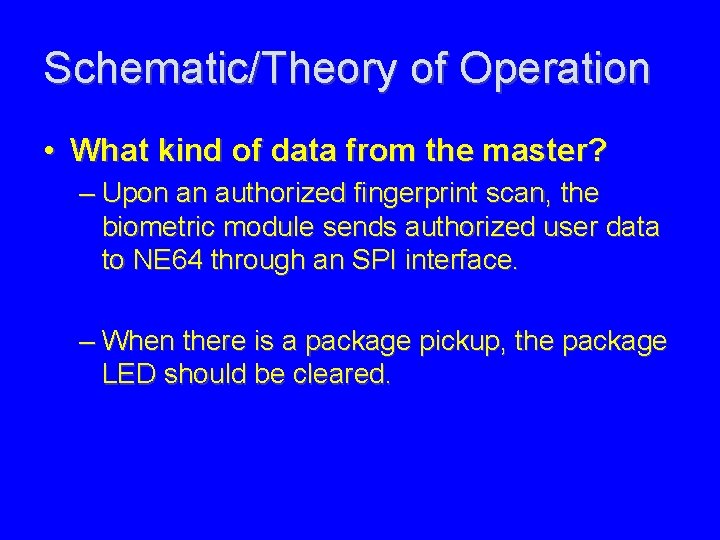
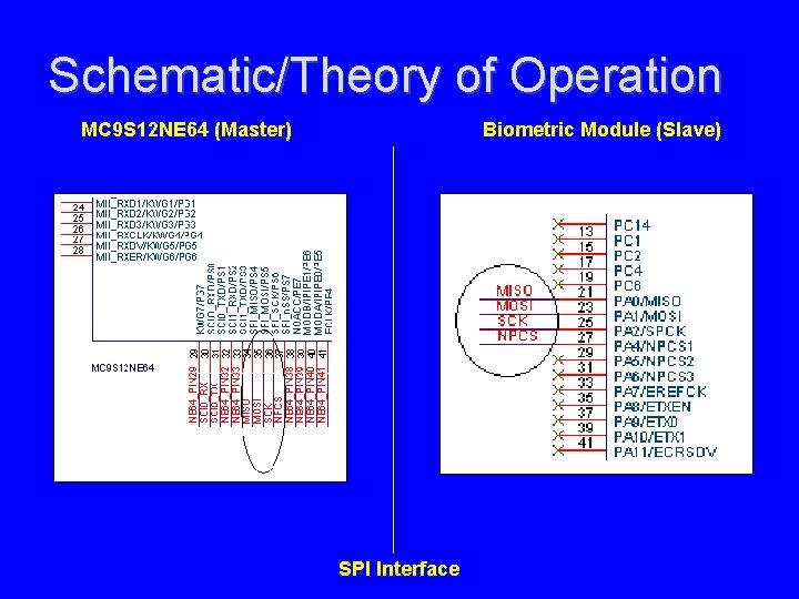
Schematic/Theory of Operation • What kind of data from the master? – Upon an authorized fingerprint scan, the biometric module sends authorized user data to NE 64 through an SPI interface. – When there is a package pickup, the package LED should be cleared.
Schematic/Theory of Operation MC 9 S 12 NE 64 (Master) Biometric Module (Slave) SPI Interface
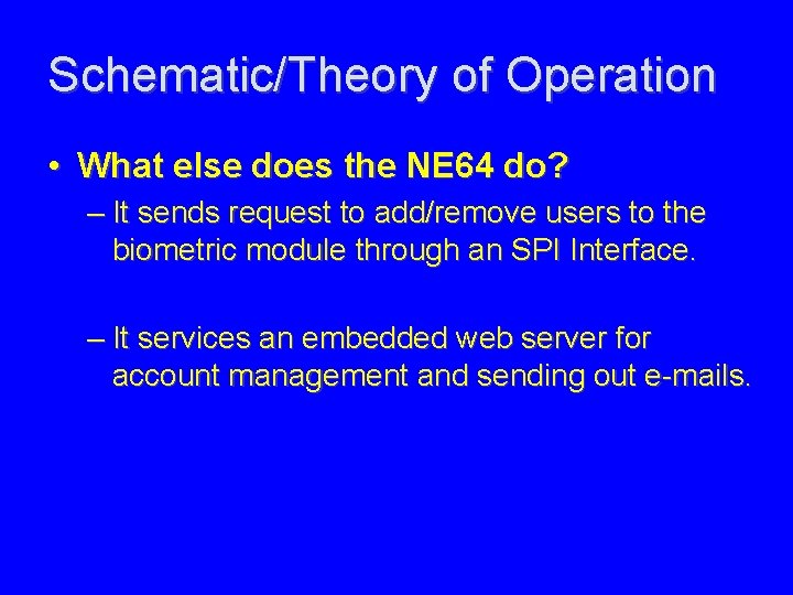
Schematic/Theory of Operation • What else does the NE 64 do? – It sends request to add/remove users to the biometric module through an SPI Interface. – It services an embedded web server for account management and sending out e-mails.
Schematic/Theory of Operation MC 9 S 12 NE 64 (Master) MC 9 S 08 GT 32 (Slaves) I 2 C Interface
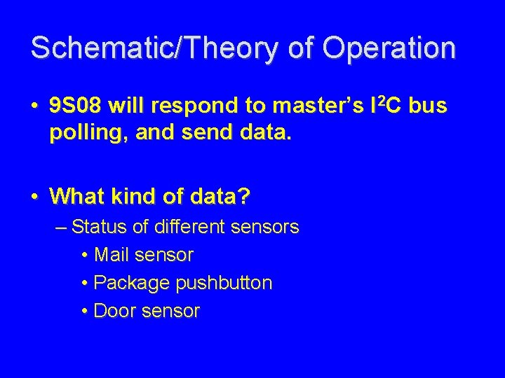
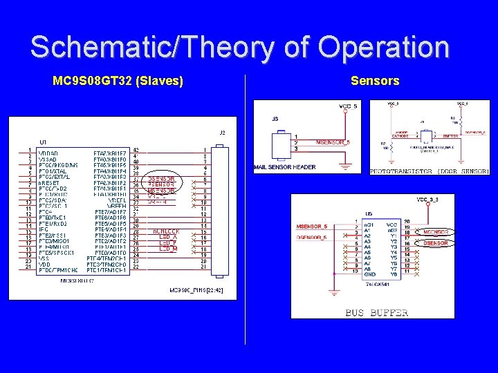
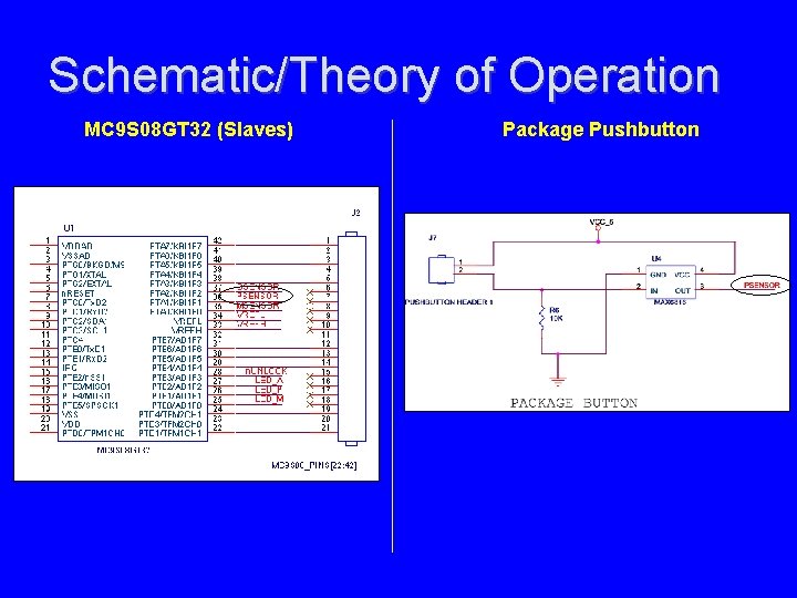
Schematic/Theory of Operation • 9 S 08 will respond to master’s I 2 C bus polling, and send data. • What kind of data? – Status of different sensors • Mail sensor • Package pushbutton • Door sensor
Schematic/Theory of Operation MC 9 S 08 GT 32 (Slaves) Sensors
Schematic/Theory of Operation MC 9 S 08 GT 32 (Slaves) Package Pushbutton
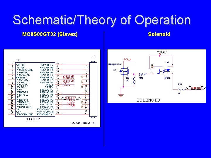
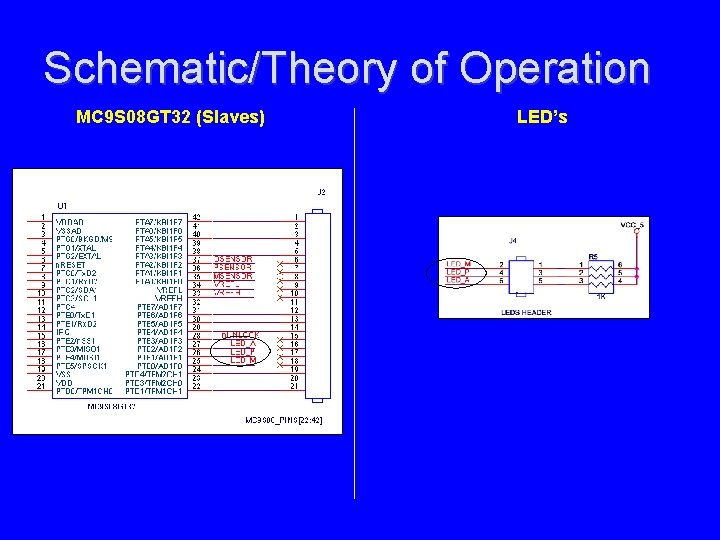
Schematic/Theory of Operation • What else does the 9 S 08 do? – It unlocks the mailbox door according to authorization information. – Sets the LED’s (Mail, Package, and Authorized) accordingly.
Schematic/Theory of Operation MC 9 S 08 GT 32 (Slaves) Solenoid
Schematic/Theory of Operation MC 9 S 08 GT 32 (Slaves) LED’s
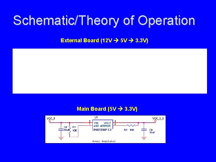
Schematic/Theory of Operation How is thing being powered?
Schematic/Theory of Operation External Board (12 V 5 V 3. 3 V) Main Board (5 V 3. 3 V)
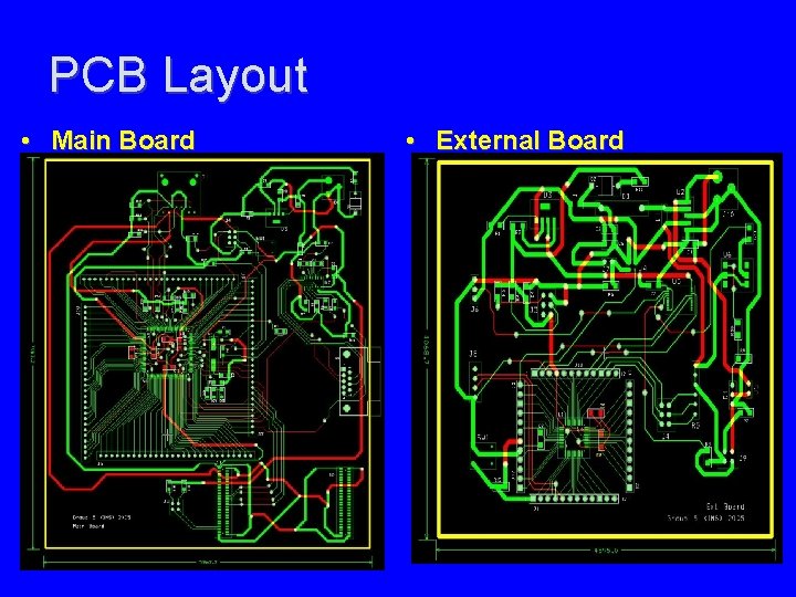
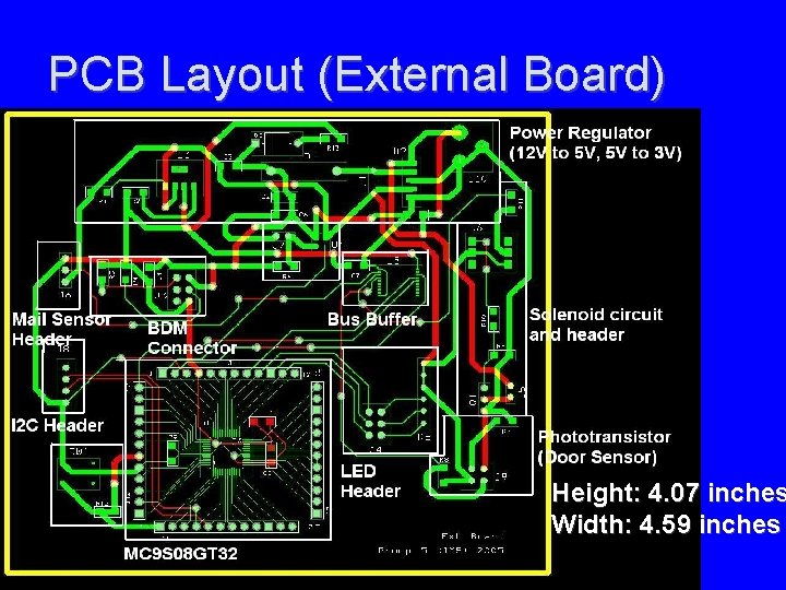
PCB Layout • Main Board • External Board
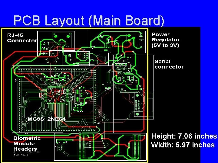
PCB Layout (Main Board) Height: 7. 06 inches Width: 5. 97 inches
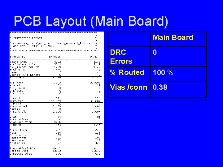
PCB Layout (Main Board) Main Board DRC Errors % Routed 0 100 % Vias /conn 0. 38
PCB Layout (External Board) Height: 4. 07 inches Width: 4. 59 inches
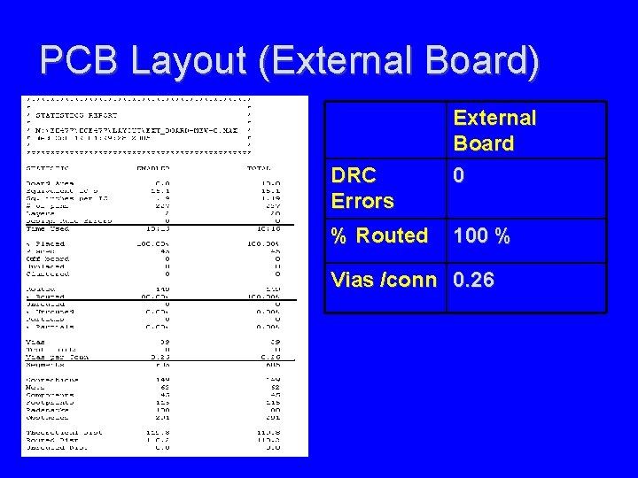
PCB Layout (External Board) DRC Errors % Routed External Board 0 100 % Vias /conn 0. 26
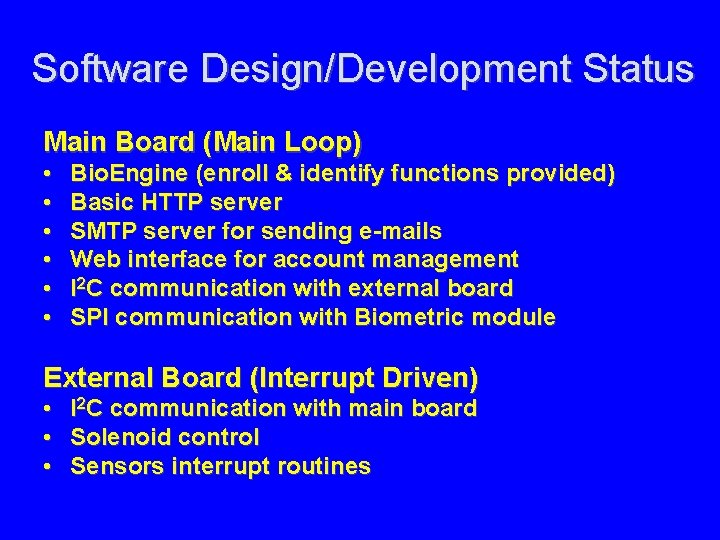
Software Design/Development Status Main Board (Main Loop) • • • Bio. Engine (enroll & identify functions provided) Basic HTTP server SMTP server for sending e-mails Web interface for account management I 2 C communication with external board SPI communication with Biometric module External Board (Interrupt Driven) • I 2 C communication with main board • Solenoid control • Sensors interrupt routines
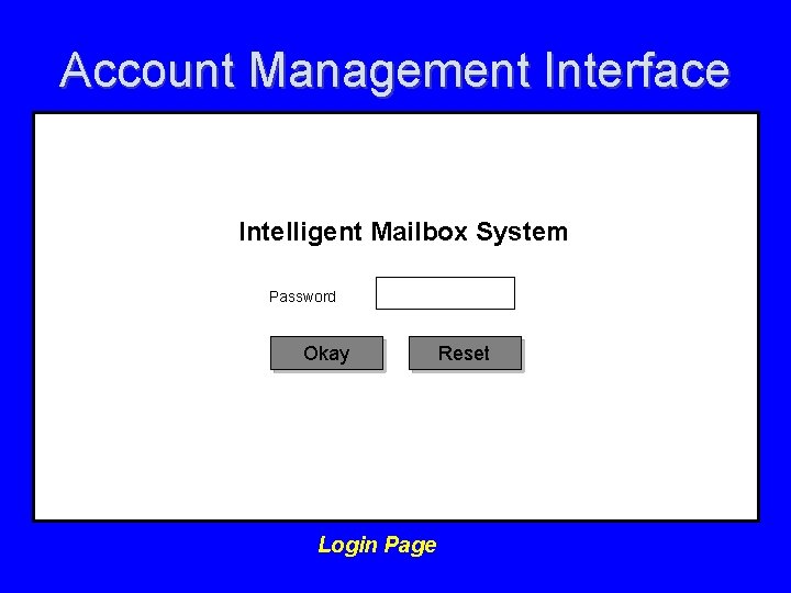
Account Management Interface Intelligent Mailbox System Password Okay Login Page Reset
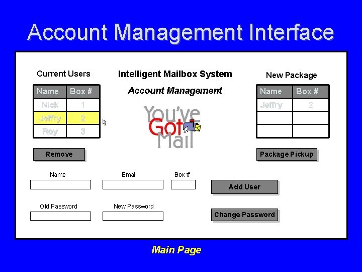
Account Management Interface Current Users Name Box # Nick 1 Jeffry 2 Roy 3 Intelligent Mailbox System Account Management Name Jeffry Remove Name New Package 2 Package Pickup Email Box # Add User Old Password Box # New Password Change Password Main Page
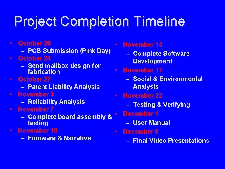
Project Completion Timeline • October 20 – PCB Submission (Pink Day) • October 24 – Send mailbox design for fabrication • October 27 – Patent Liability Analysis • November 3 – Reliability Analysis • November 7 – Complete board assembly & testing • November 10 – Firmware & Narrative • November 15 – Complete Software Development • November 17 – Social & Environmental Analysis • November 22 – Testing & Verifying • December 1 – User Manual • December 6 – Final Video Presentations
Questions / Discussion