Recovered Energy Generation CHP Waste HeattoPower Generation Workshop


- Slides: 27

Recovered Energy Generation CHP Waste Heat-to-Power Generation Workshop March 2, 2005 University of California, Irvine ORMAT Technologies, Inc. 980 Greg Street Sparks, NV 89431 -6039 USA WWW. ORMAT. COM 1

ORMAT Background Innovative power generation technologies for geothermal and heat energy recovery since 1965 Recognized world leader in the use of organic motive fluids (hydrocarbons) in power generation systems Demonstrated capabilities in design, engineering, manufacturing, installation, financing and operation of power plants Over 750 MW of geothermal and recovered heat power plants have logged 14 million operating turbine-hours, avoided emission of 12 x 106 tons of CO 2 & saved 4 x 10⁶ tons of fuel 2

Fields of Activity RECOVERED ENERGY GENERATION TRANSALASKA, SINCE 1976 RELIABLE REMOTE POWER Trans-Canada Pipeline CANADA, SINCE 1999 UPPER MAHIAO, THE PHILIPPINES, SINCE 1996 HEAVY OIL UPGRADER GEOTHERMAL POWER PLANTS 2380 a CANADA, SINCE 1999 3

1987 73 MW Ormesa Geothermal Complex, California Imperial Valley 1992 40 MW Heber Geothermal Power Plant, Imperial County, California, USA, 1992 30 MW Puna Geothermal Power Plant, Big Island, Hawaii 1996 125 MW Upper Mahiao Geothermal Power Plant, the Philippines 1994, 1998 14 MW Sao Miguel Geothermal Power Plant, Azores Islands 2000 60 MW Mokai Geothermal Power Plant, New Zealand 4

ORMAT Technology Organic Rankine Cycle Chimney Condenser Vapor exit Wheel Turbine Vapor inlet Alternator Canister Feed Pump Controls Burner Organic fluid Thermostat Fuel inlet Fuel control panel ORMAT Closed Cycle Vapor Turbogenerator ORMAT Geothermal Combined Cycle OEC Waste Heat Recovery System 5

ORMAT® Energy Converter (OEC) Closed Loop Organic Rankine Cycle Power Generation System Closed: System fully recycles working fluid, with no discharges to the environment Organic: Working fluid is a hydrocarbon or other organic fluid Rankine cycle: Standard power generation cycle used in steam turbines – OEC air cooled condenser smaller and more efficient than steam system 6

Organic Rankine Cycle System Typical Gas Turbine Application 7

OEC Operating Experience • Over 250 large OEC units comprising 750 MW • Over 3500 small CCVT units installed • Oldest units on-line since 1965 (CCVT) & 1984 (OEC) • Combined history of more than 16 million operating hours 8

Marriage of Mature Technologies • OEC recovered heat applications are a combination of: ORMAT’s commercially and field-proven OEC turbine technology Thermal oil waste heat recovery systems widely used in the petrochemical industry for decades 9

Qualified Energy Recovery A “Green” Power Technology No additional fuel consumption Near zero emissions with air cooled ORMAT Energy Converters (OECs) Inside the fence installation on existing sites. No water consumption with closed loop operation No creation or disposal of waste Displaces fossil fuel based energy 10

Entropy Diagrams for Water and Organic Fluid 11

OEC Advantages Over Steam Simpler system No blow down and replacement of working fluid No vacuum pumps or steam ejectors Air cooled Rugged design 1800 RPM turbine, direct connection to generator Outdoor installation typical (even in severe climate) Very low O&M requirements No licensed steam technicians required Packaged modular system – low installed cost 12

OEC Recovered Energy Permitting Issues Inside-the-fence installation simplifies permitting v Federal: v State: v County: v Other: Self-certification by FERC as a QF, and amendment of industry related permits. a) Amend Air Quality Permit for possible fugitive emissions from OEC, b) Inspection of OECs by OSHA, c) Amend permits to include storage of hydrocarbons on site a) Building permit for construction, b) County planning permit may require amendment. a) Amend process/safety management manuals 13

Turbine-Generator Description Turbine is single casing, multi-stage axial unit, with impulsedesign blading, directly coupled to the generator shaft Turbine designed and optimized to operate with the organic vapors. No gearbox required. Mechanical shaft seal prevents leakage of working fluid into the atmosphere or lube oil. The generator is a synchronous, air-cooled (with inlet filter), three-phase machine, brushless and weather protected NEMA II specifications, 13. 8 k. V or 4. 16 k. V and 60 Hz Single or dual shaft extension(s) with turbine directly coupled 14

Manufacturing CNC Machining CNC Measurement Organic Vapor Turbine Assembly Heat Exchangers Workshop 1476 15

YEAR OF FIRST USE REPRESENTATIVE PROJECTS 1984 1985 1989 1993 1996 Steamboat Ormesa Puna Heber Rotokawa 72 75 78 83 84 2000 Olkaria 88 2483 TURBINE EFFICIENCY % Continuous Improvement of Turbine Efficiency 16

ORMAT SELECTED ENERGY RECOVERY PROJECTS PROJECT NAME LOCAT’N MW YEAR ORMAT ROLE OWNER OPERATOR Neptune Gas Luouisiana USA 4. 0 MW 2004 EPC equipment for recovery of heat from turbine exhaust Enterprise Partners LLC. Heidelberger Cement Germany 1. 5 MW 1999 Design/supply of equipment for recovery of heat from clinker cooler Heidelberger Cement Gold Creek Canada 6. 5 MW 1999 Design/supply of equipment for recovery of heat from gas turbine exhaust Maxim Energy Minakami Japan 600 KW 1998 Design/Supply of equipment for recovery of heat from MSW Incinerator Ishikawajima Hanyoki Service TG 2 Kawerau New Zealand 3. 5 MW 1993 Design/Supply of equipment for recovery of heat from Paper Process Bay of Plenty Electric Power Board Shijiazhuang Heating & Power China 1. 3 MW 1993 Design/Supply of equipment for recovery of heat from MSW Incinerator Shaijiazhuang Thermal Power Gas Company 17

Reliable Power From Waste Heat 500 to 6500 k. W units in Canada, Germany, Japan, Spain, China and USA 6. 5 MW ORMAT® Energy Converter at a Gas Compressor Station along the Trans. Canada Pipeline, in Gold Creek, Canada, since 1999 1. 5 MW ORMAT® Energy Converter clinker cooler heat recovery system at Heidelberg. Cement AG, in Lengfurt, Germany, since 1999 18 2337

Typical Pipeline Compressor Station 19

6. 5 MW ORMAT POWER PLANT GOLD CREEK COMPRESSOR STATION TRANSCANADA PIPELINE 1502 20

Enterprise Products – Neptune Plant 21 2337

OEC in Cement Plant 22

OEC at Heidelberg Cement Lengfurt, Germany Summary Operating Experience On completion of the first year of operations the following was noted Availability over 98% Generating 17% more power than defined under design conditions Operation & maintenance costs are negligible - required spares $3000 & motive fluid loss of 0% No additional staff needed for operation of the system 23

Costs And Configuration Capital installed costs for ORMAT OEC facilities is approximately $1, 800 - $2, 000/k. W net Example: 5. 46 MW Gross/4. 81 MW Net at design conditions System is matched with exhaust heat source for optimum utilization and operational flexibility Operating costs based on experience are extremely low- less than 0. 2 cents per Kwh 24

Economics vary by application n Heat source utilization Physical configuration Value of power generated Approximately $30/MWh power over 15 year project life 25

Conclusions Proven, mature, reliable technology Economically attractive compared to other new sources of power Significant environmental benefits Many existing industrial heat sources and new CHP applications Market is responding to opportunity 26

www 2335 visit our website: 27 www. ormat. com
 California bit program
 Yenifer chp vr
 Market research igcse
 @nezupoi: title : she is working out chp.14
 What are the 5 major discourses in matthew
 Basic tools and basic hand operations
 Chp mission statement
 Chp 4
Chp 4 Chp 14
 Chp dre
 Seleccion estabilizadora
 Checed warwick apartments
 Who gets affected directly or indirectly due to accident
 Recovered memory 17
 Royalty is account
 Dr junaid mughal
 First generation antipsychotics vs second
 You are good and your mercy endureth forever
 Energy energy transfer and general energy analysis
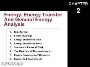
 Energy energy transfer and general energy analysis
 Waste to energy technology
 Forms of energy?
 Describing energy section 2 answers
 Site:slidetodoc.com
 Primary energy and secondary energy
 Primary energy and secondary energy
 Gibbs free energy equation
 Gibbs energy and equilibrium


