Practical Electrocardiography Introduction Scott Ewing D O Cardiology

- Slides: 74
Practical Electrocardiography Introduction Scott Ewing, D. O. Cardiology Fellow August 2, 2006
Syllabus n n n n Introduction Axis Determination Atrial Arrhythmias, Bradycardias, and AV Conduction Block Junctional and Broad Complex Tachycardias Myocardial Ischemia and Acute Myocardial Infarction Conditions Affecting the Left Side of the Heart Conditions Affecting the Right Side of the Heart Conditions Not Primarily Affecting the Heart
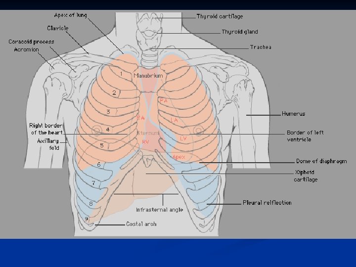
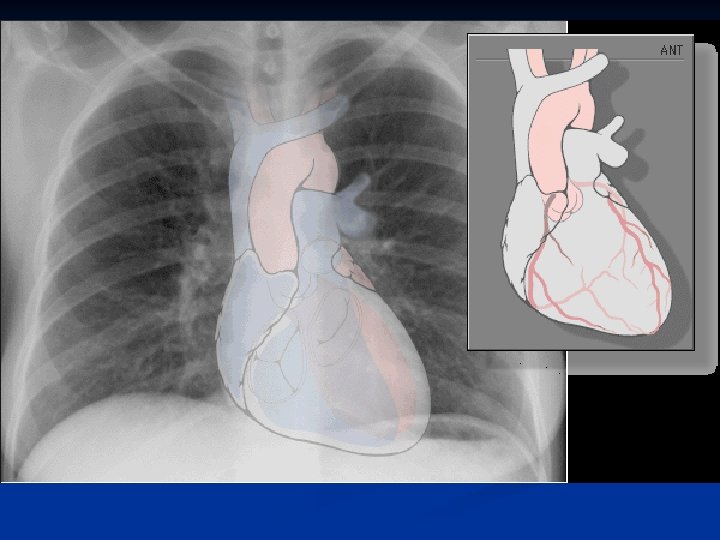
Introduction Anatomy n ECG Paper n Lead Placement n Normal ECG n Axis Determination n
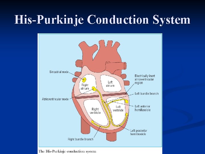
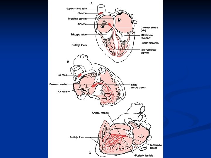
His-Purkinje Conduction System
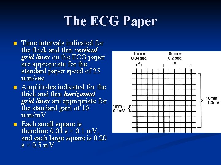
The ECG Paper n n n Time intervals indicated for the thick and thin vertical grid lines on the ECG paper are appropriate for the standard paper speed of 25 mm/sec Amplitudes indicated for the thick and thin horizontal grid lines are appropriate for the standard gain of 10 mm/m. V Each small square is therefore 0. 04 s × 0. 1 m. V, and each large square is 0. 20 s × 0. 5 m. V
Depolarization
Normal ECG
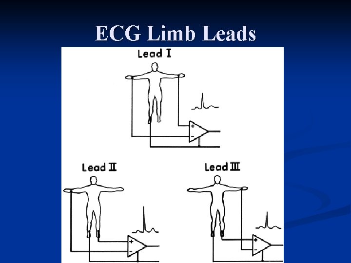
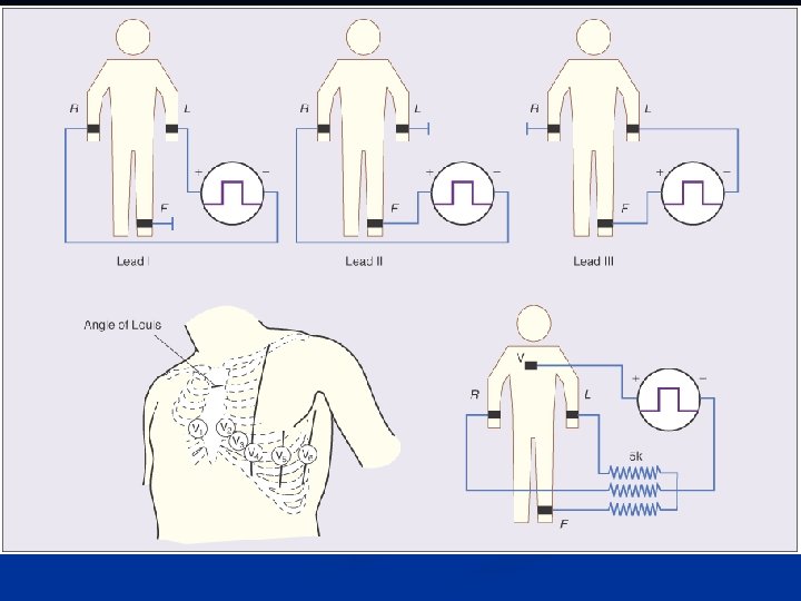
ECG Limb Leads
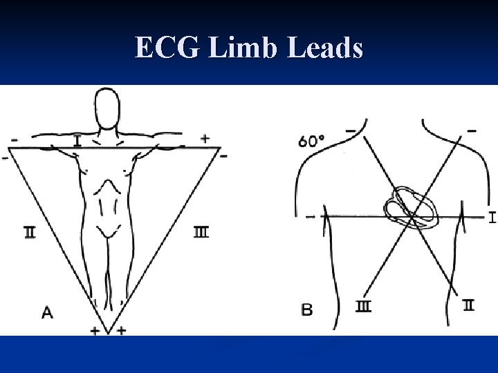
ECG Limb Leads
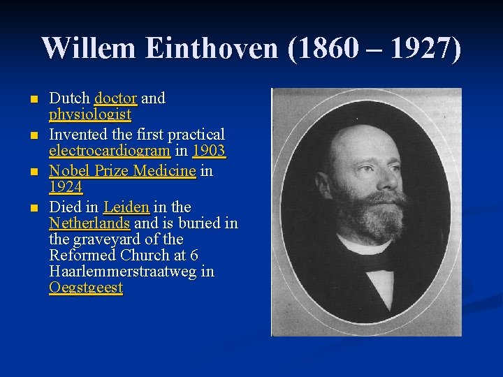
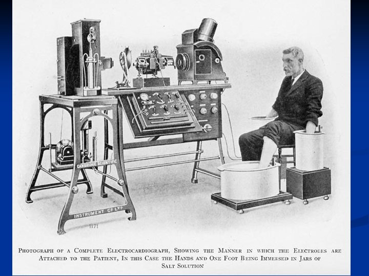
Willem Einthoven (1860 – 1927) n n Dutch doctor and physiologist Invented the first practical electrocardiogram in 1903 Nobel Prize Medicine in 1924 Died in Leiden in the Netherlands and is buried in the graveyard of the Reformed Church at 6 Haarlemmerstraatweg in Oegstgeest
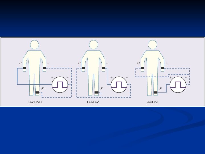
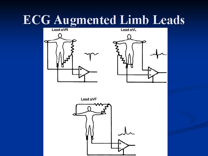
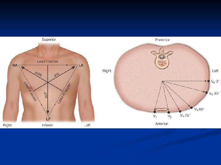
ECG Augmented Limb Leads
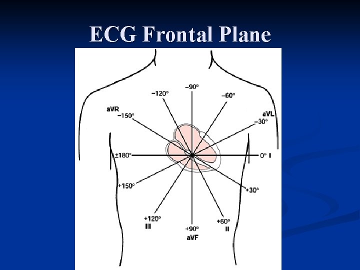
ECG Frontal Plane
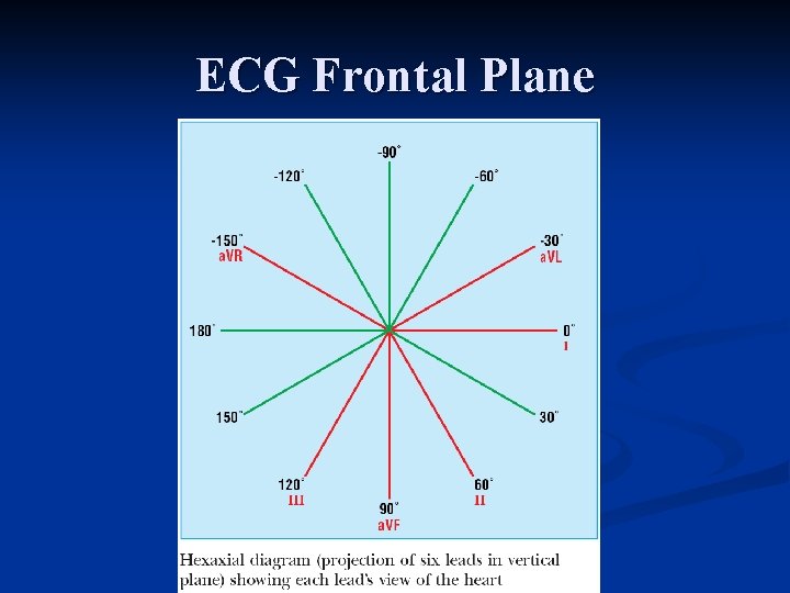
ECG Frontal Plane
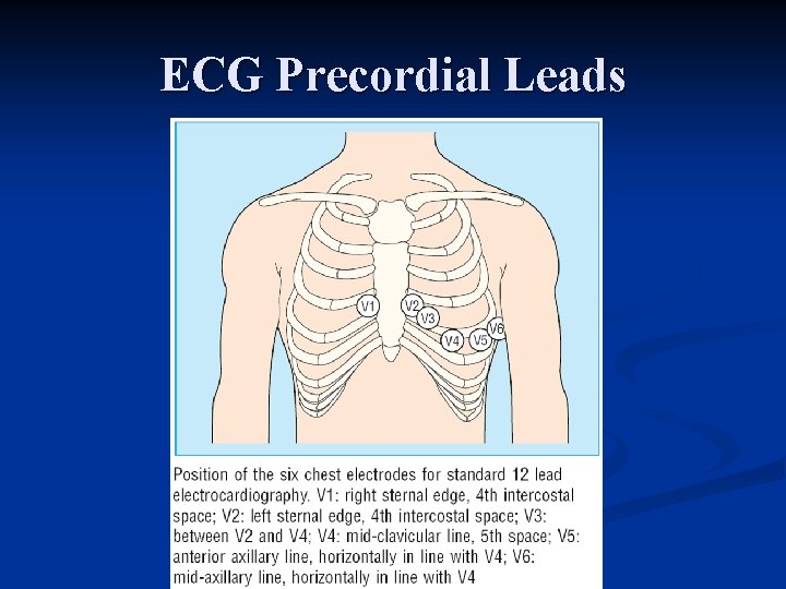
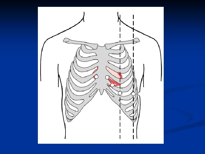
ECG Precordial Leads
Normal Findings n n n n n Tall R waves Prominent U waves ST segment elevation (high takeoff, benign early repolarization) Exaggerated sinus arrhythmia Sinus bradycardia Wandering atrial pacemaker Wenckebach phenomenon Junctional rhythm 1 st degree heart block
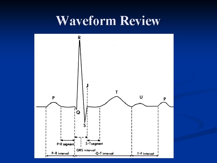
Waveform Review
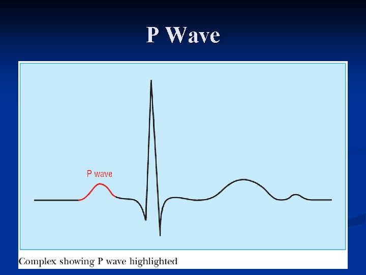
P Wave
P Wave
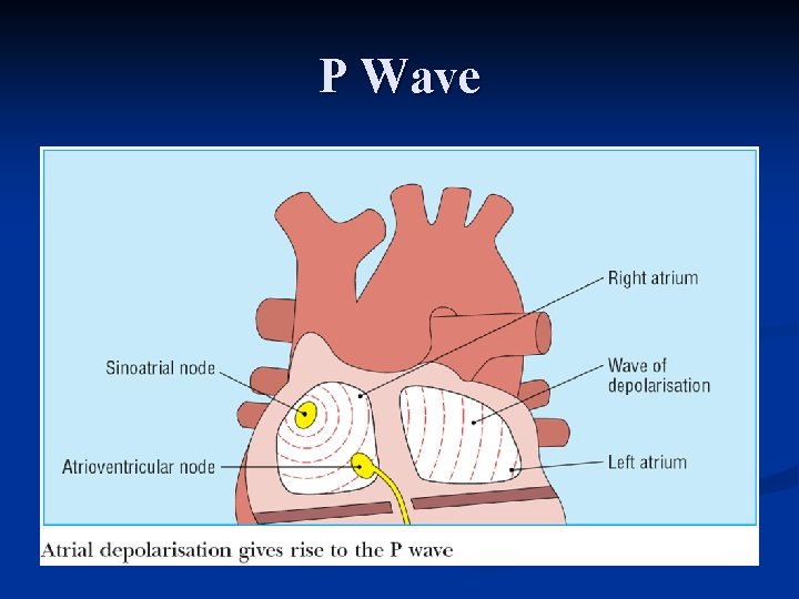
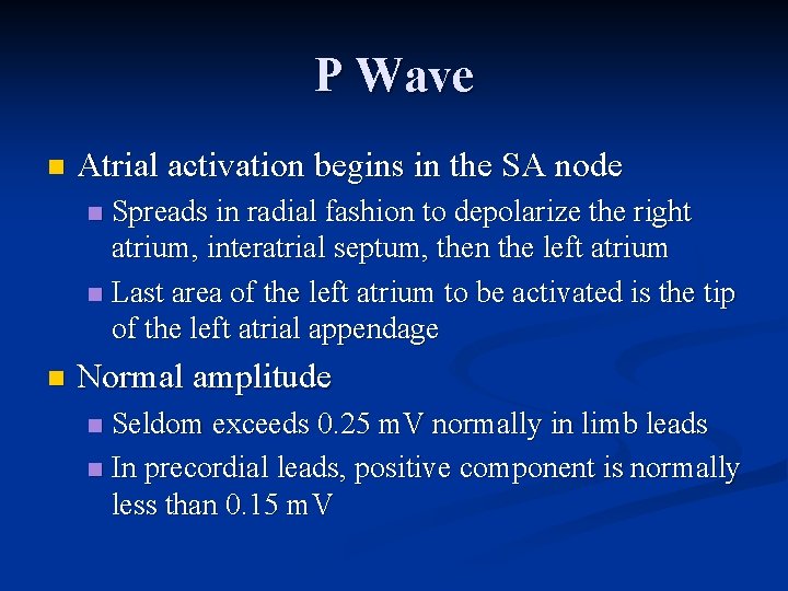
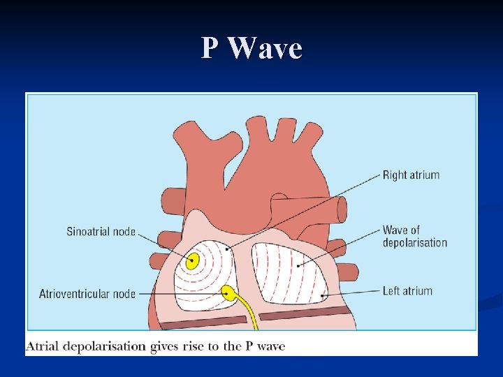
P Wave n Atrial activation begins in the SA node Spreads in radial fashion to depolarize the right atrium, interatrial septum, then the left atrium n Last area of the left atrium to be activated is the tip of the left atrial appendage n n Normal amplitude Seldom exceeds 0. 25 m. V normally in limb leads n In precordial leads, positive component is normally less than 0. 15 m. V n
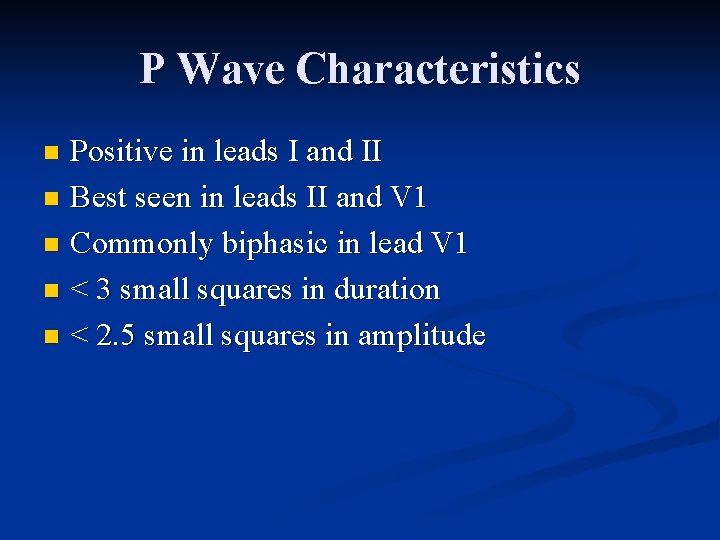
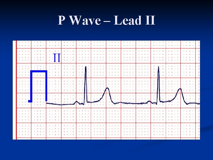
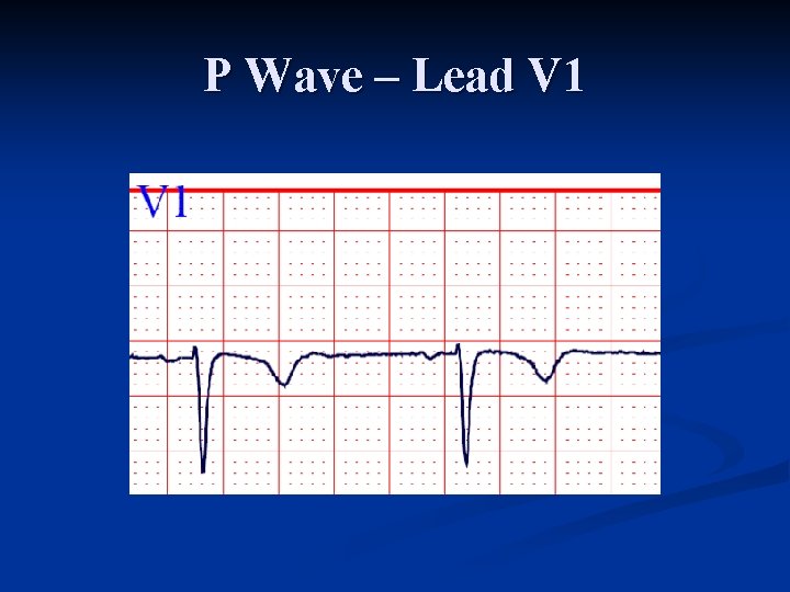
P Wave Characteristics Positive in leads I and II n Best seen in leads II and V 1 n Commonly biphasic in lead V 1 n < 3 small squares in duration n < 2. 5 small squares in amplitude n
P Wave – Lead II
P Wave – Lead V 1
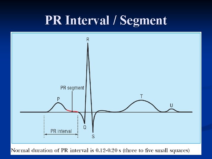
PR Interval / Segment
P Wave
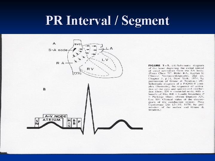
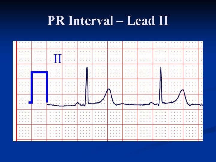
PR Interval n Beginning of P wave to beginning of QRS complex Interval between the onset of atrial depolarization and onset of ventricular depolarization n Time required for the activation impulse to advance from atria through the AV node, bundle of His, bundle branches, and the Purkinje fibers until ventricular myocardium begins to depolarize n Does not include duration of conduction from SA node proper to the right atrium n
PR Interval / Segment
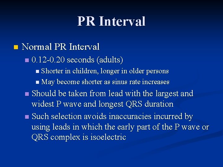
PR Interval n Normal PR Interval n 0. 12 0. 20 seconds (adults) n Shorter in children, longer in older persons n May become shorter as sinus rate increases Should be taken from lead with the largest and widest P wave and longest QRS duration n Such selection avoids inaccuracies incurred by using leads in which the early part of the P wave or QRS complex is isoelectric n
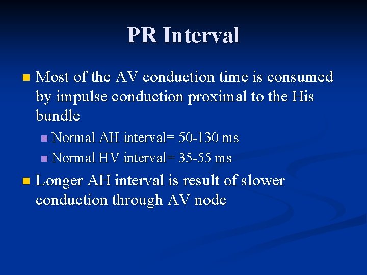
PR Interval n Most of the AV conduction time is consumed by impulse conduction proximal to the His bundle Normal AH interval= 50 130 ms n Normal HV interval= 35 55 ms n n Longer AH interval is result of slower conduction through AV node
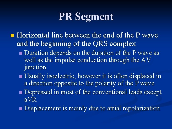
PR Segment n Horizontal line between the end of the P wave and the beginning of the QRS complex Duration depends on the duration of the P wave as well as the impulse conduction through the AV junction n Usually isoelectric, however it is often displaced in a direction opposite to the polarity of the P wave n Depressed in most of the conventional leads except a. VR n Displacement is mainly due to atrial repolarization n
PR Interval – Lead II
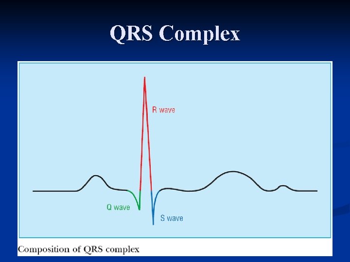
QRS Complex
QRS Complex
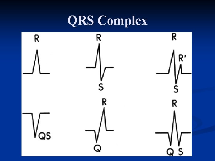
QRS Complex Q wave – Any initial negative deflection n R wave – Any positive deflection n S wave – Any negative deflection after an R wave n
QRS Complex
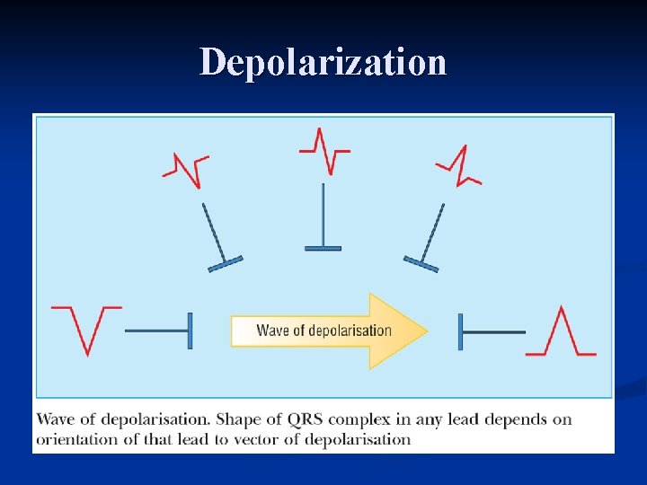
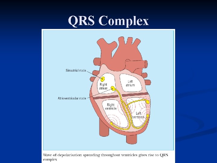
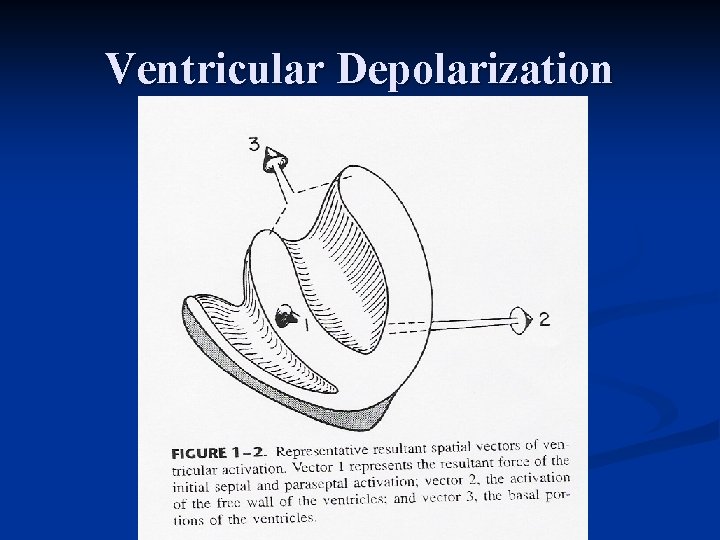
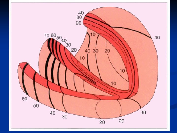
QRS Complex n Resultant electrical forces generated from ventricular depolarization Begins at the middle third of the left interventricular septal surface n Spreads in a rightward direction n Right ventricle begins to depolarize shortly after the initiation of left ventricular activation n
Ventricular Depolarization
QRS Complex Soon after septal activation, the impulse arrives at most of the subendocardial layer of the myocardium of the apical and free wall of both ventricles through the Perkinje network and spreads in all directions n Impulse spreads in endocardial to epicardial direction n
QRS Complex Basal portion of septum and the posterobasal portion of the free wall of the LV are last areas of depolarization n LV contributes most of the QRS forces due to larger muscle mass n Polarity and amplitude of the QRS complex in the various leads are determined by the relation between these vectors and the lead axes n
QRS Complex QRS duration represents duration of ventricular activation n Should be measured from lead with widest QRS complex n n n Traditionally measured from the limb leads, but V 1 or V 2 may have the widest complex Normal QRS varies between 0. 06 0. 11 second
QRS Complex n Morphology and amplitude are affected by constitutional variables Advancing age: amplitude decreases n Men > women n Blacks > whites n Thin > obese n n In limb leads, morphology depends on the orientation and amplitude of the QRS vectors in the frontal plane
QRS Complex n Lead I: usually records a dominant R wave n In younger subjects with more rightward axis, R/S ratio < 1 may be seen Lead II: invariably has prominent R wave since mean vector is always toward II if QRS axis is normal n Lead a. VR: always records negative deflection n Lead III: variable – Why? n
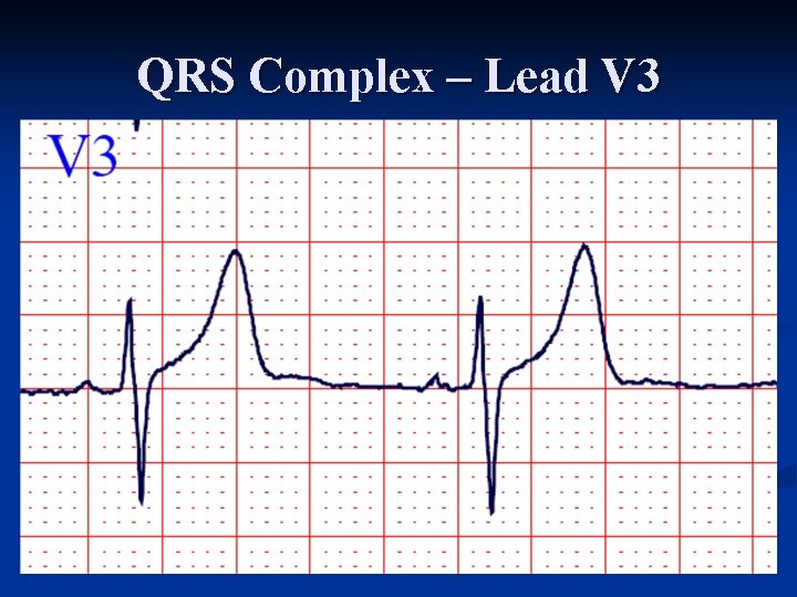
Intrinsicoid Deflection Represents the moment when the epicardial muscle lying under the electrode becomes depolarized n Beginning of the abrupt downstroke after the R wave reaches its peak n Time of onset measured from beginning of QRS to point of abrupt downstroke n Used mostly in diagnosis of ventricular hypertrophy and BBB when onset is delayed n
QRS Complex – Lead V 3
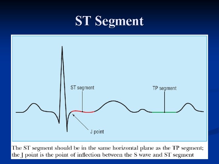
ST Segment
ST Segment n Segment between end of QRS complex (J point or ST junction) and beginning of the T wave Represents a state of unchanged polarization between the end of depolarization and the beginning of repolarization n Stage when terminal depolarization and starting repolarization are superimposed and cancel each other n
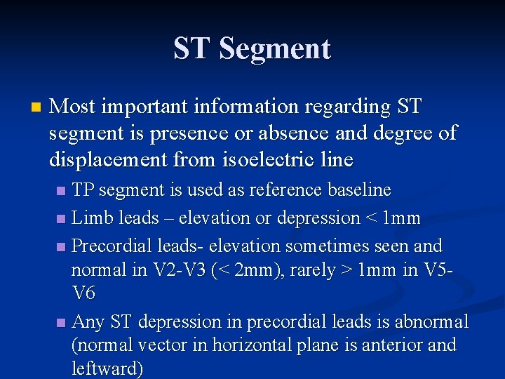
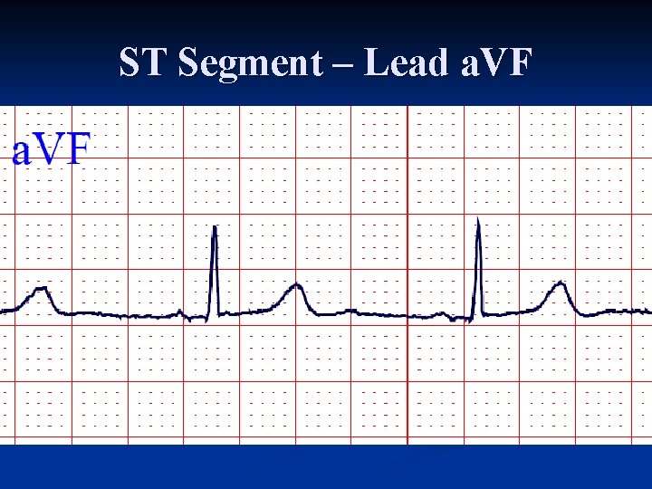
ST Segment n Most important information regarding ST segment is presence or absence and degree of displacement from isoelectric line TP segment is used as reference baseline n Limb leads – elevation or depression < 1 mm n Precordial leads elevation sometimes seen and normal in V 2 V 3 (< 2 mm), rarely > 1 mm in V 5 V 6 n Any ST depression in precordial leads is abnormal (normal vector in horizontal plane is anterior and leftward) n
ST Segment – Lead a. VF
T Wave
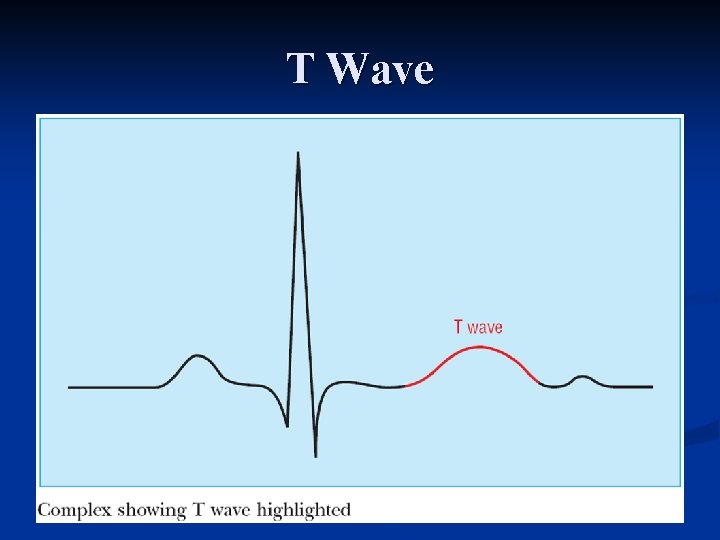
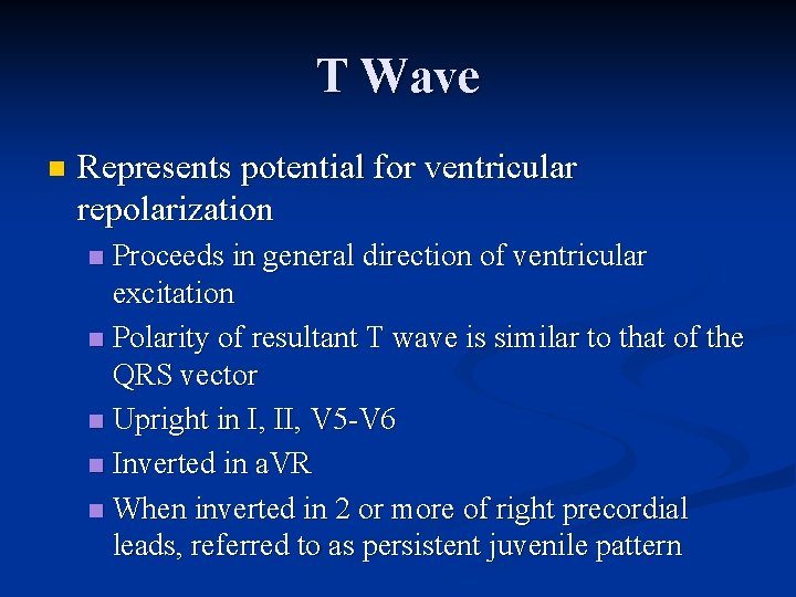
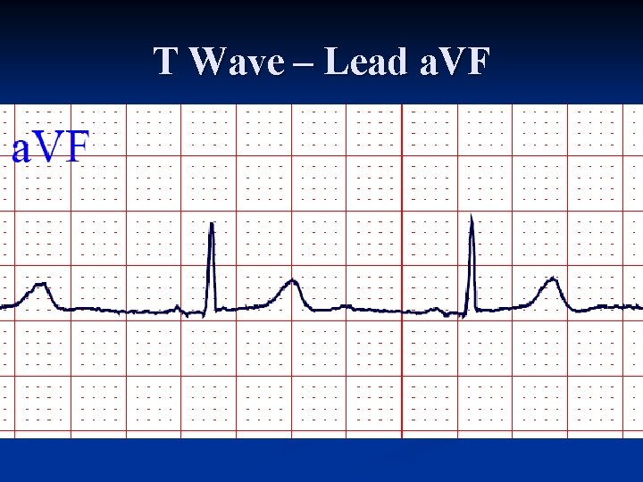
T Wave n Represents potential for ventricular repolarization Proceeds in general direction of ventricular excitation n Polarity of resultant T wave is similar to that of the QRS vector n Upright in I, II, V 5 V 6 n Inverted in a. VR n When inverted in 2 or more of right precordial leads, referred to as persistent juvenile pattern n
T Wave n Limb leads Tallest in lead II n Normally < 6 mm in all limb leads n Should never be < 0. 5 mm n n Precordial leads: Tallest in V 2 V 3 (average 6 mm) n Smaller in left precordial leads n
T Wave n n n Normally asymmetrical First half has more gradual slope than second half First portion has upward concavity if T wave is upright and downward concavity if T wave is inverted In right precordial leads, if T wave is biphasic, the first portion is upright and second portion inverted Negative positive biphasic T wave is abnormal in leads V 1 V 3
T Wave – Lead a. VF
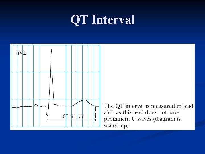
QT Interval
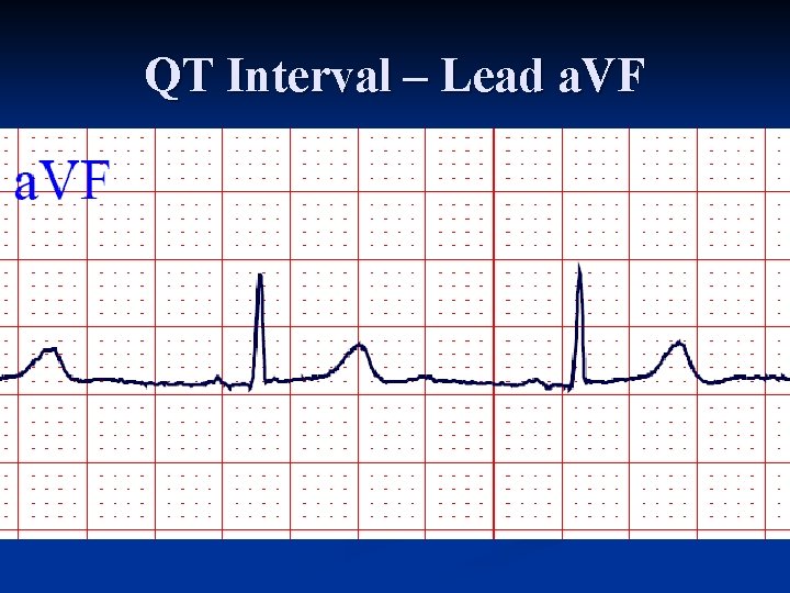
QT Interval Represents duration of ventricular electrical systole n Measured from beginning of QRS complex to end of the T wave n Lead with a large T wave and distinct termination is used n Leads V 2 V 3 are usually best for this specific measurement n
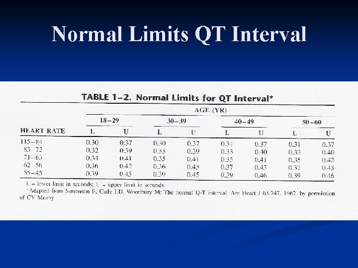
QT Interval n Varies with heart rate (see table) Lengthens as heart rate decreases n Shortens as heart rate increases n Increases slightly with age n Diurnal variation of QTI has been documented n n Longer during sleep than during waking hours
Normal Limits QT Interval
QT Interval n Normal = 0. 35 – 0. 45 second for HR=70 n n Bazett's correction n n For every 10 beat increase or decrease of the rate, 0. 02 second is deducted or added to the QTI QTc = measured QTI divided by square root of RR interval Obvious abnormality if QTI > ½ RR interval
QT Interval – Lead a. VF
U Wave
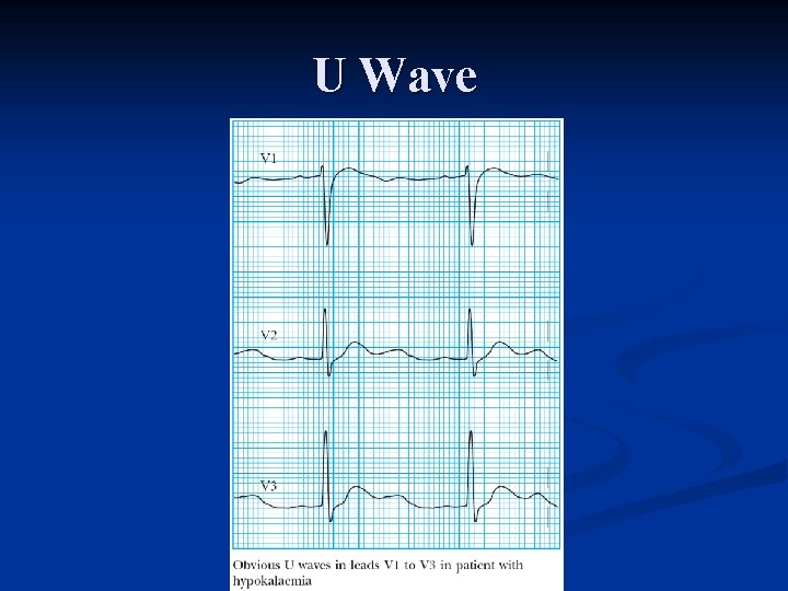
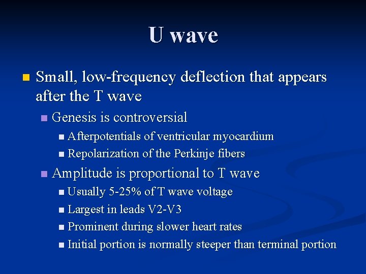
U wave n Small, low frequency deflection that appears after the T wave n Genesis is controversial n Afterpotentials of ventricular myocardium n Repolarization of the Perkinje fibers n Amplitude is proportional to T wave n Usually 5 25% of T wave voltage n Largest in leads V 2 V 3 n Prominent during slower heart rates n Initial portion is normally steeper than terminal portion
Conclusion n Questions?