PODSTAWY EKSPLOATACJI Wykad 7 Ukady gazowoparowe Dobr urzadze

PODSTAWY EKSPLOATACJI Wykład 7: Układy gazowo-parowe Dobór urzadzeń prof. dr hab. inż. Konrad Świrski

bar C 16 1 580 1 1500 12 -26 300 -400 15

1 bar 105 C 1 580 80 535
![CC plants in Poland Power Plant year Electric capacity Thermal capacity [MW] [MWt] EC](http://slidetodoc.com/presentation_image_h/00b1e50d44abcfff4c57719d0e14c571/image-12.jpg "CC plants in Poland Power Plant year Electric capacity Thermal capacity [MW] [MWt] EC")
CC plants in Poland Power Plant year Electric capacity Thermal capacity [MW] [MWt] EC Gorzów 1999 55 65 EC Nowa Sarzyna 2000 116 70 EC Lublin Wrotków 2002 235 150 EC Rzeszów 2003 101 76 EC Zielona Góra 2004 190 95 Stalowa Wola 2014 (2020) 450 30 Włocławek 2016 (2017) 463 Płock 2018 615 Gorzów 2017 153 EC Żerań 2021 250 Dolan Odra 2023 2 x 683
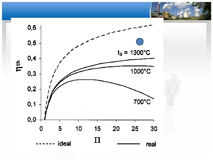

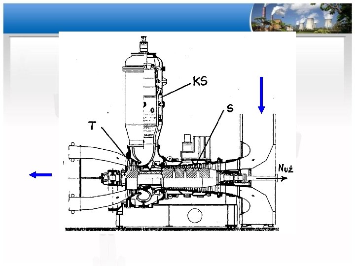
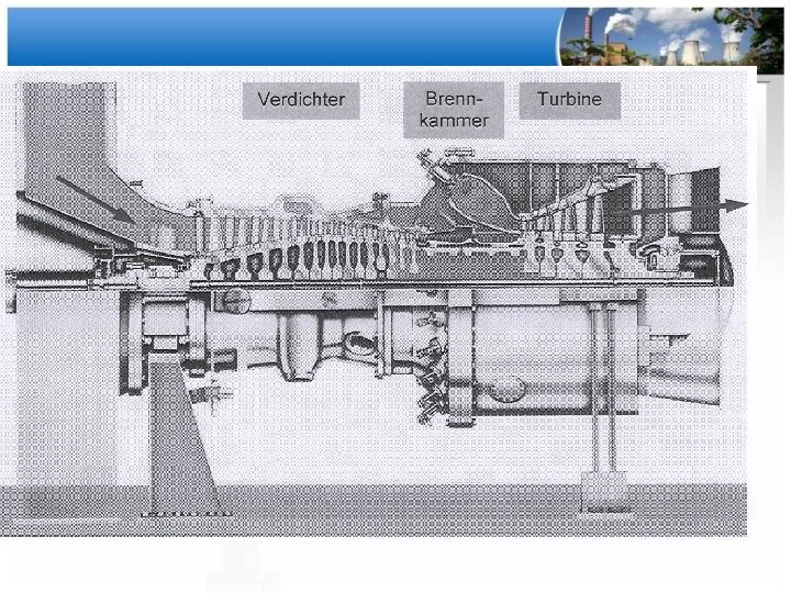
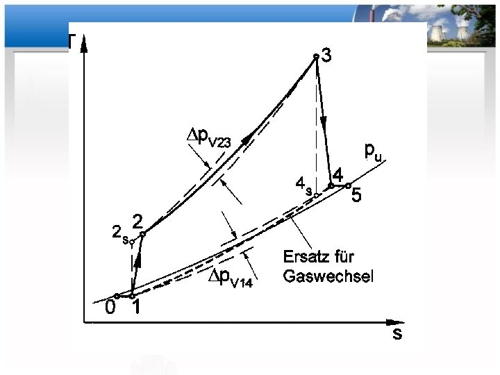
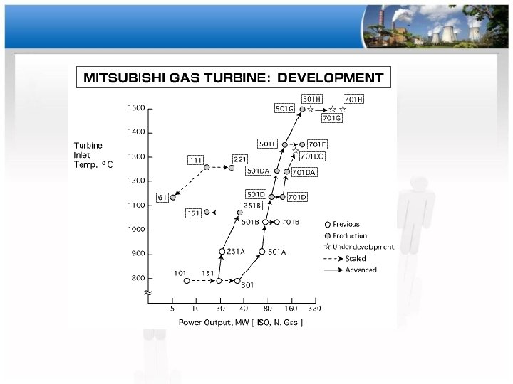
Podstawowe wielkości charakteryzujące turbinę gazową - stosunek ciśnień w sprężarce - stosunek ciśnień w turbinie - sprawność izentropowa sprężarki - sprawność izentropowa turbiny - sprawność komory spalania - sprawność obiegu

Sprawność w funkcji mocy TG

Zużycie paliwa w funkcji mocy

Zmiana ciśnienia wylotowego

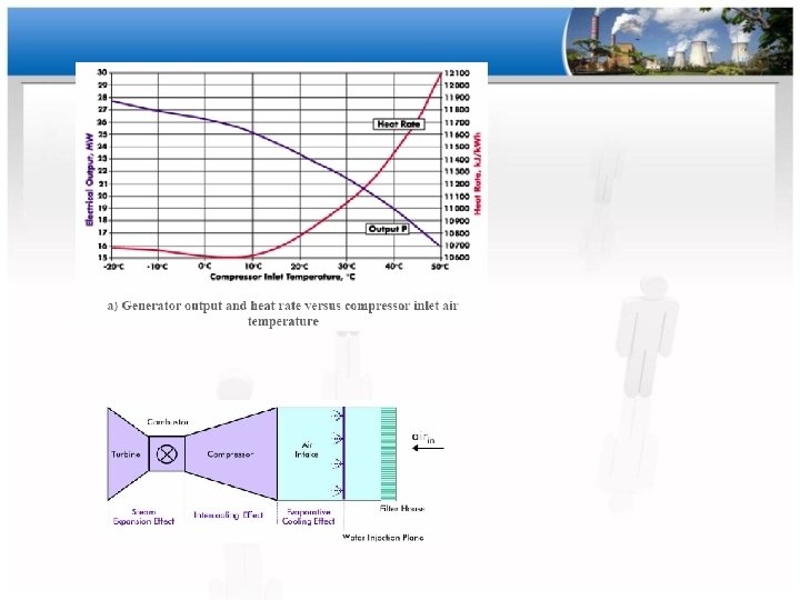
Wpływ temperatury wlotowej na osiągane parametry

Parametry eksploatacyjne turbin gazowych • Norma europejska ISO 2314 – – Temperatura wlotowa 15 C Ciśnienie 1, 013 bar Wilgotność względna 60 % Koncentracja NOx przeliczona na 15% O 2 w spalinach
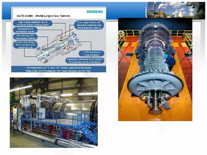
 • Siemens SGT 5 -8000 H")
Turbina gazowa • 340 MW (teraz 425 MW) • Siemens SGT 5 -8000 H • Instalacja Ingolstat, Niemcy

GE – 445 MW

30

Rekordowe wyniki Turbina gazowa 425 MW 446 MW 544 MW Sprawność układ prosty 42 -45 % Sprawność układ kombinowany 62, 22 % Siemens SGT 5 -8000 H GE 9 HA. 01 GE 9 HA. 02 GE (Bouchain France)

Rozruch bloku energ. na węgiel

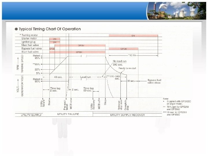
Rozruch turbiny gazowej
 Rodzaj przeglądu Godziny pracy Uruchomienia Komory spalania")
Przeglądy serwisowe dla dużych turbin gazowych (GE) Rodzaj przeglądu Godziny pracy Uruchomienia Komory spalania 8000 800 Hot-gas path (układ przepływowy spalin) Przegląd główny 24000 800 48000 2400

Praca TG Praca ciągła cykliczna szczytowa rezerwa
 Godziny pracy/ilość uruchomień Stand-by (rezerwa) Peaking")
Praca turbin gazowych Praca Wykorzystanie (service factor %) Godziny pracy/ilość uruchomień Stand-by (rezerwa) Peaking (szczytowa) Cycling (cykliczna) Continuous (ciągła) < 1 % 1 -4 1 -17 % 3 -10 17 -50 % 10 -150 >90 >>150

Odstawienie TG

Odstawienie bloku na węgiel

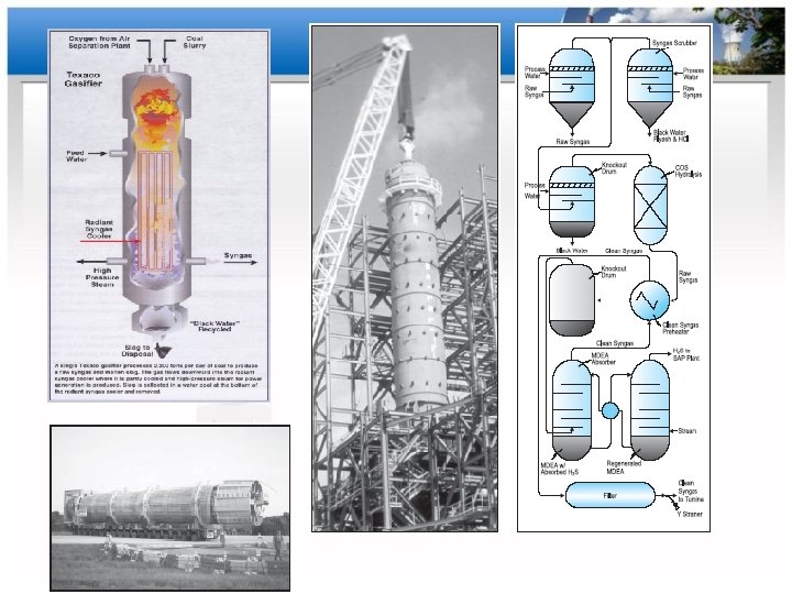
Układy IGCC

IGCC • IGCC – Integrated Gasification Combined Cycle • Zgazowanie węgla – Metoda powietrzna lub O 2 – Gaz ze zgazowania • Wartośc opałowa 4 -5 tys k. J/Nm 3 (gaz naturalny 50 000 k. J/Nm 3) • Zawartość H 2 S i innych związków siarki w gazie ze zgazowanie (bo S w węglu) – konieczność usunięcia przed spaleniem w turbinie gazowej

Projekt referencyjny Do. E USA – Tampa Electric IGCC 250 MWe

Problemy z usunięciem związków siarki • Proces zgazowania - Gaz ze zgazowania o wysokiej temperaturze 900/1500 – 2000 C • Metody usunięcia siarki (katalityczne) – tylko dla spalin o temp. ok. 150 C • Gorący gaz jest chłodzony (para z układu parowego) a następnie podawany do turbiny gazowej i spalany

• niezawodność – 83, 5 % gasifier – 94 % combined cycle • 36, 5 % sprawności – Konwersja wegla na gaz – 95 %

• Finalnie układy IGCC przestają być budowane i planowane • Węgiel (przynajmniej w planach UE) przestaje być paliwem energetycznym (lata 2030 -2040) • Węgiel wciąż jest używany (i ew planowany w układach IGCC – koncepcyjnie) w Indie, Chiny, inne kraje azjatyckie

Praca własna

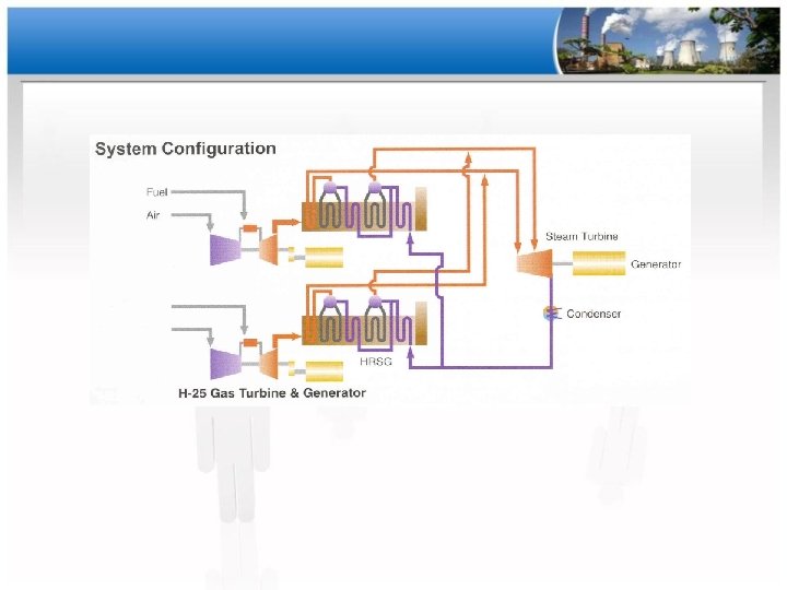
Projekt układu CC • postępujemy wg instrukcji • Mamy do dyspozycji turbiny danego producenta (każda z grup ma turbiny od jednej firmy) • Wybieramy turbiny (i blok gazowo-parowy) do spełnienia warunków technicznych • Przedstawiamy schemat i dane technologiczne (na rysunku)
")
Materiały dodatkowe O uruchamianiu turbin gazowych (angl)

Startup sequence • • Gas turbine is not self starting device and require outside source of power for startup (at 25 -30 % speed)(usually diesel engine or electric motor, sometomes steam turbine or gas expander, for big turbines startup via generator using variable frequency power supplies) Starting sequence – Crancing device started – rotor speeds up passing firing speed up to purging speed held for necessary purging period (1 -10 min) ( some simple cycle does not require purging) – After purging rotor decelerate to ignition speed (optimal – thermal fatigue duty and reliable ignition) and ignition sequence starts • Spark plugs, firing fuel flow, detection of flame • Reducing fuel to warm-up vale (about 1 minute) – Acceleration - Increasing fuel flow after warm up period according to acceleration porgram (5 -10 min) • About 40 % - 85 % speed – no cranking power • 80 -90 % speed inlet guide vanes open (prior closed to prevent surge) • Synchronization – Matching turbine generator speed (also sometimes voltage) – Closing the breaker – Load control (increase of fuel flow) (5 -10 min)

Control During Startup • Startup Control The startup control sets fuel commands for firing, warm-up, and acceleration limit for starting and accelerating the gas turbine to operating speed. • Acceleration Control The acceleration controls the acceleration rate of the gas turbine during the acceleration to operating speed. The acceleration control output is restricted by the minimum fuel limit to maintain flame. • Speed Control The speed controls the speed of the gas turbine at operating speed when the turbine is not synchronized to the power system. The speed control is restricted by the minimum fuel limit. When the turbine is synchronized, the speed controls the load on the turbine - FUEL FLOW

Normal turbine operation • Load Control The load controls the load of the gas turbine to a selectable set point of spinning reserve, pre-selected, and max load set point with a base or a peak load limit based on temperature control. Load is controlled by changing the speed/load set point - FUEL FLOW – • Fuel Control System The fuel stroke reference is passed to the gas and liquid fuel systems via the fuel control signal divider in accordance with the operator fuel selection of the gas and liquid fuel systems. The gas fuel control system is composed of the gas fuel pressure control and the gas fuel flow control. The gas fuel control valve controls the gas flow, which is proportional to the fuel command. The liquid fuel control system achieves fuel flow control by recirculating excess fuel from the discharge back to the pump suction through the bypass valve. Exhaust Temperature Control The exhaust temperature control regulates fuel in order to provide a controlled temperature increase or decrease and an upper limit for normal operation. The median value of thermocouples sorted highest to lowest is the exhaust temperature feedback. – LIMITS FUEL AND CONTROLS AIR FLOW – via GUIDE VANE CONTROL – Inlet Guide Vane Control The inlet guide vane (IGV) control modulates the IGV angle on a schedule of corrected speed, which is a function of the compressor inlet temperature and the gas turbine speed when the gas turbine is started up. The IGV control also modulates the IGV angle to maintain high exhaust temperature during part load. The load brings the IGV angle to open due to increasing exhaust temperature. The IGV control program depends on the operation type selected of simple cycle operation and combined cycle operation

Control during shutdown • Shutdown Control At generator breaker open, the shutdown control ramps the current fuel stroke reference to the minimum fuel limit and ramps to fuel shutoff at a defined condition for the purpose to reduce thermal fatigue duty imposed on the hot gas path parts.

Control Protection • • Combustion Monitor The combustion monitor detects abnormal combustion temperature patterns reflected downstream in exhaust temperature spreads. Gas Turbine Protection The gas turbine protection system prevents abnormal conditions, which could result in damage to the gas turbine. The critical operating parameters monitored by the protection system are temperature, speed, vibration, flame, fire, lube oil pressure and compressor operating limit. The running reliability of the gas turbine control system is also monitored. The protection system trips the gas turbine if its signal corresponds to a trip condition through the triple-redundant master controller.

Gas Turbine Functions • • • Startup Control Acceleration Control Speed Control Load Control Exhaust Temperature Control Inlet Guide Vane Control Shutdown Control Fuel Control System Combustion Monitor Gas Turbine Protection

Speed Control Legend CPU Central Processing Unit ESD Emergency Shutdown GG Gas Generator GTFC Gas Turbine Fuel Control HS High Select LS Low Select NGG Gas Generator Speed NPT Power Turbine Speed PID Proportional - Integral - Derivative PLC Programmable Logic Controller PT Power Turbine T 2 Gas Generator Inlet Temperature T 5 Gas Generator Exhaust Gas Temperature
- Slides: 56