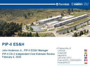
PIPII 121 03 Accelerator Systems Paul Derwent PIPII


- Slides: 33

PIP-II 121. 03 Accelerator Systems Paul Derwent PIP-II Machine Advisory Committee Meeting 25 -27 March 2019 In partnership with: India/DAE Italy/INFN UK/STFC France/CEA/Irfu, CNRS/IN 2 P 3

Outline • 121. 03 L 2 System Scope, Deliverables, & Requirements • Design Plan • Key Technical Issues – Cavity Resonance Control – Laser Profile Monitor – Controls System Modernization • Cost and Schedule Status • Summary 2 25 -27 March 2019 Derwent | 121. 03 Accelerator Systems P 2 MAC meeting

121. 03 L 2 System Scope • Labor, materials, travel, and other costs associated with the management, design, procurement, fabrication, and testing of various accelerator system hardware and software including High Power RF, RF distribution, Low Level RF, Magnets, Power Supplies, Vacuum, Controls, Safety Systems, and Instrumentation. WBS Dictionary : pip 2 -docdb #599 3 25 -27 March 2019 Derwent | 121. 03 Accelerator Systems P 2 MAC meeting

L 3 Scope and Deliverables • L 3 systems – 121. 03. 06 Vacuum – 121. 03. 02 Machine Protection • Fast Beam Permits – 121. 03 High Power RF • Linac Amplifiers & Distribution – 121. 03. 04 Low Level RF • Linac RF Stations & Interlocks • Resonance Control – 121. 03. 05 Magnets & Power Supplies • Super. Conducting Linac and Beam Transfer line • Warm Magnets • Cold & Warm Magnet Power Supplies WBS Dictionary : 4 25 -27 March 2019 Derwent | 121. 03 Accelerator Systems • Cryomodule Insulating Vacuum • Linac and Transfer Line Beam vacuum – 121. 03. 07 Controls • Timing, Machine Protection • Infrastructure – 121. 03. 08 Safety Systems • Electrical, Radiation, ODH • Interlocks and Monitoring – 121. 03. 09 Instrumentation • Linac and Beam Transfer Line • Beam diagnostics • Electronics pip 2 -docdb #599 P 2 MAC meeting

L 3 Scope and Deliverables • Linac and Beam Transfer Line Tunnel Components – – – – – Beam Pipe Vacuum Pumps, Gauges Dipoles, Quadrupoles Beam Position Monitors, Beam Loss Monitors, Toroids, DCCT Profile Monitors, Emittance Monitors RF Distribution Cables Interlocks & Enclosure gates Timing Reference Line • Test Stands – Cavity and Cryomodules • HPRF, LLRF • Vacuum • Power Supplies 5 25 -27 March 2019 Derwent | 121. 03 Accelerator Systems • Gallery Components – – RF Amplifiers & Distribution LLRF Stations Power Supplies Electronics • Diagnostics • Machine Protection • Controls – Infrastructure • Ethernet, Data Logging, Programmable Logic Controllers, Motion Control • Software and firmware deliverables are associated with many systems P 2 MAC meeting

In Kind Contributions • 121. 03 RF Power Amplifiers for: – ALL SSR 1 (325 MHz, 7 k. W) • 8(+1) amplifiers for PIP 2 IT to power SSR 1 Cryomodule – ALL SSR 2 (325 MHz, 20 k. W) – ALL LB 650 (650 MHz, 40 k. W) • 6 Amplifiers for HB 650 CM test at PIP 2 IT • 2 Amplifiers for test stands with other partners (France, UK) • • – ALL HB 650 (650 MHz, 70 k. W) 121. 03. 04 LLRF and RF Protection Interlocks (RFPI) – Test stand 325 MHz, 650 MHz – 1 CM apiece 325 MHz, 650 MHz 121. 03. 05 Warm magnets – ALL SC Linac Quadrupoles and dipole correctors • All India Contributions under India Institutes Fermilab Collaboration (IIFC) • Further contributions are under discussion 6 25 -27 March 2019 Derwent | 121. 03 Accelerator Systems P 2 MAC meeting

System Requirements • Accelerator Systems tie together main pieces of the Linac configuration. The various aspects of this level 2 structure provide for RF power and control of the accelerating cavities in the Linac, for magnets and associated power supplies to focus the H- beam, for beam and insulating vacuum systems, for instrumentation to measure beam characteristics, for safety systems to protect personnel, for machine protection systems to protect hardware, and for control and user interface to all the various components. They also contribute systems to the various test stands necessary to test prototype and production components. 7 25 -27 March 2019 Derwent | 121. 03 Accelerator Systems P 2 MAC meeting

121. 03 L 3 Functional Requirements Specifications WBS # L 3 System Team. Center ED# 121. 03. 02 Machine Protection TBD 121. 03 High Power RF 8023 121. 03. 04 Low Level RF 4194 121. 03. 05 Magnets & Power Supplies 8059 121. 03. 06 Vacuum 8216 121. 03. 07 Controls 8101 121. 03. 08 Safety Systems 8061 121. 03. 09 Beam Instrumentation 8303 Machine Protection recently promoted from L 4 to L 3, still working on project documentation Documents available to the committee through Indico 8 25 -27 March 2019 Derwent | 121. 03 Accelerator Systems P 2 MAC meeting

System Interfaces • Accelerator Systems interface everywhere WBS # L 3 System Team. Center ED# 121. 03. 02 Machine Protection TBD 121. 03 High Power RF 7688 121. 03. 04 Low Level RF 7689 121. 03. 05 Magnets & Power Supplies 7690 121. 03. 06 Vacuum 7691 121. 03. 07 Controls 7692 121. 03. 08 Safety Systems 7693 121. 03. 09 Beam Instrumentation 7694 Machine Protection recently promoted from L 4 to L 3, still working on project documentation Documents available to the committee through Indico 9 25 -27 March 2019 Derwent | 121. 03 Accelerator Systems P 2 MAC meeting

Design Plan: Preliminary Design Schedule 10 25 -27 March 2019 Derwent | 121. 03 Accelerator Systems P 2 MAC meeting

Design Plan: Preliminary Design Schedule 11 25 -27 March 2019 Derwent | 121. 03 Accelerator Systems P 2 MAC meeting

Technical Progress to Date • Resonance Control algorithms – Testing with SSR 1 cavities at the Spoke Test Cryostat and lessons from LCLS-II testing • Preparations for HWR and SSR 1 CM at PIP 2 IT – Amplifiers, circulators, LLRF stations, Instrumentation electronics, vacuum, controls, QPMs, power supplies, Oxygen Deficiency Hazard (ODH) and Rad Safety interlocks – Every L 3 has had to advance design, interfaces, procurements to support these operations • Hardware demonstration (many at PIP 2 IT) – HPRF – – 12 • RFQ, buncher cavities • Coupler test stands (325 & 650 MHz at STC) LLRF • RFQ, buncher cavities • Beam pattern generator for Medium Energy Beam Transport (MEBT) chopper Beam diagnostics • BPMs, Time of Flight • Beam Current Monitors • Emittance Scanners • Low Power Laser Profile monitor Vacuum • Warm to cold vacuum transition performance tested Magnets and Power Supplies • Quench Protection Monitor prototype with SSR 1 solenoid 25 -27 March 2019 Derwent | 121. 03 Accelerator Systems P 2 MAC meeting

RF Development • Test stands at STC – Couplers at 325 MHz and 650 MHz – 650 MHz Inductive Output Tube (IOT) Amplifier and power distribution – Preparations for the Horizontal Tests of 650 MHz cavities 13 25 -27 March 2019 650 MHz LLRF Station for Horizontal Tests Derwent | 121. 03 Accelerator Systems P 2 MAC meeting 650 MHz Coupler Test Stand

Beam Instrumentation – Prototype Wire Scanner at PIP 2 IT Installed and beam tested in PIP 2 IT MEBT Vert Horz Beam Current 14 25 -27 March 2019 Derwent | 121. 03 Accelerator Systems P 2 MAC meeting

Vacuum tests at PIP 2 IT • Transition from warm MEBT to cold HWR – Protect against vacuum accidents contaminating SRF • Testing at PIP 2 IT – Controlled leaks – Observe response • Gas flow, pressure match model calculations 15 25 -27 March 2019 Derwent | 121. 03 Accelerator Systems P 2 MAC meeting

QPM Prototype Test • HWR and SSR CMs contain superconducting magnets – Quench Protection Monitor hardware to: • Detect quench • Remove power from magnets – Complete Prototype system designed and tested in VTS • Drove systems to quench with heaters • Design Review: Sept 27 2018 – TC ED 0008375 • Procurement of QPMs to support HWR and SSR 1 at PIP 2 IT 16 25 -27 March 2019 Derwent | 121. 03 Accelerator Systems Quench Detector V threshold -1 V Magnet Load Voltage d. I/dt P 2 MAC meeting

Resonance Control: Challenges • Baseline for the SRF section is for CW RF with pulsed beam operation • Amplifier power requirements are based on expected peak detuning (microphonics) – The project has chosen 20 Hz peak detuning as a conservative value. LCLS-II has a 10 Hz peak requirement • Using piezo actuators to control slow system tuning changes is “easy” • Some labs report success using piezo actuators to correct some audio-band perturbations in SRF cavity tuning; not “easy” • The current plan leverages the LCLS-II resonance control approach and will make use of development for that project and also the considerable work done at FNAL 17 25 -27 March 2019 Derwent | 121. 03 Accelerator Systems P 2 MAC meeting

Resonance Control: Mitigations • Due to the overall risk to the project, it is important to mitigate this risk as soon as possible. Steps to this are: – Ensure that Low Level RF system hardware designs continue to include full resonance control capabilities. – Take full advantage of any cold cavity time in single cavity test stands and full cryomodule testing at PIP 2 IT and CMTS. – Modify Berkeley’s real-time cavity simulator and incorporate measured transfer functions. – Continue to develop algorithms based of past work at FNAL and also on LCLS-II resonance control. 18 25 -27 March 2019 Derwent | 121. 03 Accelerator Systems P 2 MAC meeting

Resonance Control: Opportunity • Opportunity for pulsed operation – While pulsing the cavity RF could dramatically reduce cryogenic loads and wall power, it would also add to the cavity detuning. RF peak power therefore increases. Engineering effort increases as attempts are made to understand correct the Lorentz Force Detuning. – PIP 2 IT : opportunity to investigate this mode of operation 19 25 -27 March 2019 Derwent | 121. 03 Accelerator Systems P 2 MAC meeting

Laser Profiler Monitor Challenges • Cross section is small & beam current is small need higher laser power • BUT causes laser safety issues, potential vacuum window damage danger to SC cryomodules • Transport laser through fibers but this limits laser power • Increase sensitivity by modulating laser and using lock-in amplifier for detection • Test at PIP 2 IT April 2020 20 25 -27 March 2019 Derwent | 121. 03 Accelerator Systems H- + g H o + e - P 2 MAC meeting

Prototype Laser Wire Profiler at PIP 2 IT MEBT • Components all coming together • Laser and optics testing underway in A 0 laser lab • Testing and characterizing laserwire • PIP 2 IT vacuum chamber constructed • PIP 2 IT Laser hut nearly complete • Need to install safety interlock system Ready for testing with beam in April 2020 Laserwire Laser Hut Laser System under test in A 0 laser lab 21 25 -27 March 2019 PIP 2 IT Door Derwent | 121. 03 Accelerator Systems P 2 MAC meeting

Controls System Challenge • PIP-II control system will be based on EPICS • PIP-II Operation depends on the control system for the booster, recycler, MI, etc. • Custom system created for the Tevatron in the early 80’s – Known as ACNET – Supports the diverse modes of operation required here • Many substantial upgrades over the years, but • Many aging components, both hardware and software must be updated prior to PIP-II operations – Not part of PIP-II scope 22 25 -27 March 2019 Derwent | 121. 03 Accelerator Systems P 2 MAC meeting

Controls System Plans and Status • List of highest priority hardware items submitted as part of lab wide modernization plan • Much more must be done, including software • Accelerator Division wide working group formed to – – Assess current system Prioritize needed upgrades, propose solutions Propose possible plans including cost and schedule Consider integration with PIP-II in this process • Cosylab consultant will be part of this effort • Goal is a preliminary report by the end of summer • Determine how to execute plan when scale is better known 23 25 -27 March 2019 Derwent | 121. 03 Accelerator Systems P 2 MAC meeting

Technical -> Financial Risks Title RI-ID Probability Cost Impact Schedule Impact P * Impact (k$) P * Impact (months) RT-121 -03002 RF Power Amplifiers have technical issues 50 % 20 -- 600 k$ 0 -- 3 months RT-121 -03003 High Power Circulator fails 50 % 10 -- 50 k$ 0 -- 12 months 15 3. 0 RT-121 -03004 SSR 1 RF Power Amplifiers have technical issues 50 % 10 -- 50 k$ 0 -- 2 months 15 0. 5 RT-121 -03001 Resonance control and field regulation do not meet requirements 10 % 100 -- 3000 k$ 2 -- 24 months • Based on cost and schedule impact to the project 24 25 -27 March 2019 Derwent | 121. 03 Accelerator Systems P 2 MAC meeting 155 0. 8 1. 3

Labor (FTEs) Total: 196 FTEs 25 25 -27 March 2019 Derwent | 121. 03 Accelerator Systems P 2 MAC meeting

Materials (base cost) 26 25 -27 March 2019 Derwent | 121. 03 Accelerator Systems Total: $38. 4 M P 2 MAC meeting

Schedule Chart Accelerator Systems Machine Protection System PIP 2 IT MPS PIP-II High Power RF and RF Distribution PIP 2 IT RF Power TI RF Power HPRFRFDist PIP 2 IT LLRF TI Magnets and Power Supplies PIP 2 IT TI Mag. PS Vacuum PIP 2 IT Vac PIP-II RF Power Low Level Radio Frequency PIP-II Linac PIP-II BTL PIP-II Linac Controls PIP-II BTL-BAL PIP 2 IT Cntrl PIP-II Safety Systems PIP 2 IT SS PIP 2 IT BI BPM Legend Preliminary Design Review Final Design Review Ready for Installation 27 25 -27 March 2019 PIP-II Beam Instrumentation Derwent | 121. 03 Accelerator Systems P 2 MAC meeting PIP-II BCM BPro. MS BLM

Plan for next 4 Months • Get ready for HWR and SSR 1 RF tests – RF Distribution, LLRF, RFPI, Vacuum • Get ready for PIP 2 IT beam operation (April 2020) – Vacuum, Controls, Instrumentation, Safety Systems, Machine Protection, Magnets & PS, HPRF, LLRF • Support Cavity test stands for 325 MHz and 650 MHz – RF Distribution, LLRF, RFPI • Design advancement for Preliminary and Final Design Steps • Supporting project work towards CD 2 – Finalize Requirements and Interface Control Documents 28 25 -27 March 2019 Derwent | 121. 03 Accelerator Systems P 2 MAC meeting

Summary • Understand system scope, requirements, and deliverables • Have a design plan, in the context of the project design plan – Preliminary and Final Design cycles – Implemented in the Project Schedule • Technical progress on several fronts detailed • Identified Key Technical Issues and Risks – Plan to address them at PIP 2 IT and in Development process • Credible Cost & Schedule baseline developed for the project based on the technical design and progress 29 25 -27 March 2019 Derwent | 121. 03 Accelerator Systems P 2 MAC meeting

End 30 25 -27 March 2019 Derwent | 121. 03 Accelerator Systems P 2 MAC meeting

Design Plan: Final Design Schedule 31 25 -27 March 2019 Derwent | 121. 03 Accelerator Systems P 2 MAC meeting

Design Plan: Final Design Schedule 32 25 -27 March 2019 Derwent | 121. 03 Accelerator Systems P 2 MAC meeting

Wire Scanner for Transverse Profiles • Prototype wire scanner for transverse profiles – Horizontal and Vertical – Installed and Tested at PIP 2 IT – For use in MEBT and Beam Transfer Line Horizontal 33 25 -27 March 2019 Vertical Derwent | 121. 03 Accelerator Systems P 2 MAC meeting
 Alaga'upu fa'asamoa
 Derwent innovation
 Derwent whittlesey
 Whittlesey agricultural regions
 Transformational leadership questionnaire
 Criticism of accelerator theory of investment
 Biztalk swift
 Netbackup accelerator forced rescan
 Fiscal policy ib
 Accelerator coherency port
 Financial accelerator
 Offshore wind accelerator
 Proton
 Vmware backup best practices
 Dating
 Open capi
 Extensor: an accelerator for sparse tensor algebra
 Avamar ndmp
 Charter network accelerator
 Accelerator
 Accelerator
 Microsoft virtual machine converter solution accelerator
 United way social innovation accelerator
 Ccat azure accelerator
 Cern accelerator complex
 Growth accelerator coach
 Ads accelerator
 Medical particle accelerator
 Salesforce cpq accelerator
 Sandra biedron
 Talent accelerator program
 Stanford linear accelerator tours
 Tca color accelerator drops
 Synchrotron radiation


