PART III TRACK STRUCTURE Part 1 Turnouts Introduction


 – It is the joint")
 Ø Curved Switches Point")


 Ø For")


 n. For existing works (BG) : 95 mm")


 • It is a imaginary point")


 The location where tongue rail acquires full head width is")

")


 Crossing")


 : It is")


- Slides: 59
PART III TRACK STRUCTURE Part 1 Turnouts – Introduction 1. 1 - Turnouts, Definition and description of components (Total Periods- 3)
Turnout • Turnout is a track structure which permits movement of train from one track to another. It is the most complicated component of track. • Few inherent geometrical deficiencies in the design of turnout , affect the smooth riding over them. • Its complicated design and certain inherent deficiencies, restrict speed on turnout while negotiating towards turnout side. • Till recently it was limited to 15 kmph which has now been increased to 30 KMPH for 1 in 12.
Turnout • New design of turnout laid on concrete sleepers is sturdier than the earlier designs and permits higher speed on turnout side ( Increased speed from 15 to 30 and planning for 50 on turnout side). • Turnout on PSC sleeper requires less maintenance compared to old design.
A turnout has three Portions 1. Switch assembly 2. Lead assembly 3. Crossing assembly
Switch assembly • Tongue rail – It is a tapered moveable rail connected at its thick end to lead rail. The tapered end is called as Toe and thick end is called a Heel. • Stock rail – It is a running rail against which tongue rail functions. • Switch – A pair of tongue rails without stock rails with necessary fittings and connections (Stretcher bars). • Point – A pair of tongue rails with their stock rails is termed as a point.
Stand at the SRJ and look towards the turnout. If the turnout side is towards right hand, it is called right hand switch, and if it is going towards left, it is called left hand switch Right Hand Left Hand Movement Direction
Facing Point : Turnouts on which trains are to be received from SRJ side are called facing point Facing point Trailing Point : Turnout on which trains are received from crossing side from any of the two tracks are called trailing point. Trailing Point Movement Direction
Components of turnout.
Components/features in switch assembly • Stock rail joint (SRJ) – It is the joint at which the stock rail is joined to the rail at approach. Both stock rail joints of points are kept opposite to each other.
Components/Features of switch assembly n. Theoretical Toe of Switch (TTS) Ø Curved Switches Point of intersection of the tangent drawn to the gauge line at the toe of tongue rail and gauge of stock rail line n. Actual Toe of Switch (ATS) The points where tips of tongue rails touch the stock rails.
Curved Switch TTS ATS Tongue Rail Stock Rail
Distance between TTS to ATS • TTS to ATS = t cot β • t = thickness of tongue rail • β = Switch entry angle • For 1 in 8. 5 it is 439 mm • For 1 in 12 and 1 in 16 it is - 0 mm i. e ATS and TTS is at one location
Components/Features of switch assembly n. Switch Entry Angle or Switch angle (SEA) Ø For Curved Switches Angle contained between the gauge line of stock rail and imaginary tangent drawn at the toe of switch to the curved gauge line of the tongue rail
Components/Features of switch assembly Throw of Switch Ø The distance through which a tongue rail moves at its toe from its closed position to open position. Ø This distance is measured from the gauge line of the stock rail to inside (non gauge face) of the open tongue rail. Ø It is measured at actual toe of switch Throw
Throw of Switch THROW
Minimum Throw of Switch (SOD 2004) n. For existing works (BG) : 95 mm n. For new works/alterations to existing works(BG) : 115 mm n. The clearance can be increased up-to 160 mm in curved switches in order to obtain adequate clearance between gauge face of stock rail and back face of tongue rail (Same done for thick web switch)
Minimum Throw of Switch Ø RDSO lr no No. 2018 l. Sig/33 -SEM/1 dated 22. 04. 2019 Ø As per IRSEM part 11 Addendum and Corrigendum Slip No. 12 • Clearance limit between toe of open switch and stock rail shall be • (i) For normal and curved switches: 115 ± 3 mm i, e : 112 mm to 118 mm • (ii) For thick web switches: 160 ± 3 mm i, e: 157 mm to 163 mm
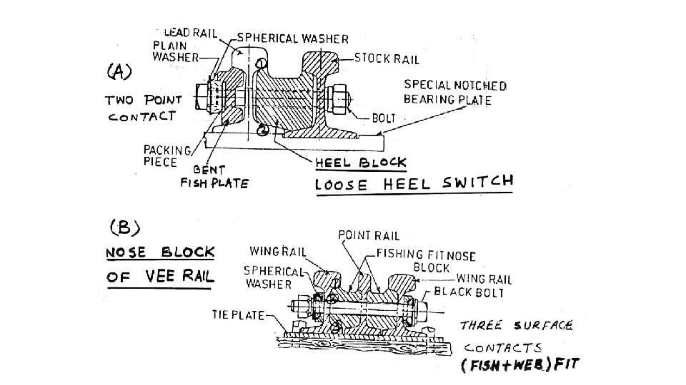
Fixed heel switch • In this type tongue rail does not end at heel of switch but extends further and makes the joint with lead rail. • The tongue rail is rigidly connected to the stock rail at heel of switch with web fit block and all bolts are spanner tight. • The movement of thin end of tongue rail is made on account of flexibility being longer in length.
Fixed Heel Switch Heel Block Joint Formed Ahead Of Heel
Fixed Heel Switch Min. Clearance at JOH HEEL BLOCK Joint Formed after Heel 20
Components/Features of switch assembly Heel of switch (HOS) • It is a imaginary point on the gauge line of tongue rail opposite the centre line of the heel block in case of Fixed heel switch. • Heel block is the first block from the toe side of tongue rail.
Fixed Heel Switch Heel Block Joint Formed Ahead Of Heel
Components/Features of switch assembly • Switch Length or Length of switch: • Switch length is the effective length of a tongue rail which moves laterally during setting of the points or it is distance from the heel of the switch to the actual toe of switch. • Normally, length of switch should be more than the longest wheel base or the maximum distance between any two wheels of the adjacent wagons on safety consideration • For Fixed heel Length of tongue rail > Switch length
Fixed Heel Switch Length of tongue rail Switch Length Heel Block Joint Formed Ahead Of Heel
Components/Features of Points & Crossings • Heel Divergence • The distance between the gauge line of stock rail and tongue rail at the heel of switch is called Heel Divergence • Measured at right angle to the gauge face of stock rail • Clear distance between the heads of tongue rail and stock rail is called Heel Clearance n. Heel Divergence = Heel Clearance + head width of Tongue Rail
Stock Rail d c Tongue Rail Heel of Switch c = heel clearance d = heel divergence Heel Divergence Heel Block
Components/Features of Points & Crossings Heel Divergence Gauge Turnout Straight / Curved incl TWS PSC Heel divergence BG 1 IN 8. 5 Curved incl TWS PSC 182. 5 mm BG 1 IN 12 Curved incl TWS PSC 175 mm BG 1 IN 16 Curved incl TWS PSC 145 mm Note: Heel divergence of 1 in 8 ½ & 1 in 12 curved switches on PSC sleepers is more because the heel is located at longer distance, at a place where the moveable length of tongue rail is flexible enough to be operated with a fixed heel.
• Lead of turnout : It is the track portion between heel of switch to the beginning of crossing assembly. Lead of turnout is measured from theoretical nose of crossing to the heel measured along the straight track of switch. • Overall length of turnout : Overall length of turnout is the distance from stock rail joint to the heel of crossing measured along the straight. Overall length of turnout
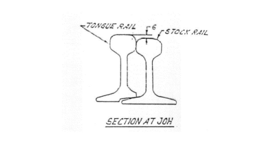
Junction of Heads (JOH) The location where tongue rail acquires full head width is called JOH. Minimum clearance at JOH is an important parameter in design & manufacture of tongue rail
Fixed Heel Switch Min. Clearance at JOH HEEL BLOCK Join. At Formed after Heel 30
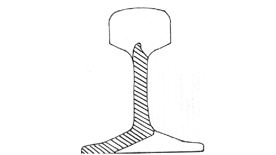
Tongue Rail (for Over-Riding Switches)
Tongue Rail
• Machining of tongue rail: Tongue rails are machined heavily so as to make tip of tongue rail thin and low that when pressed against stock rail, wheel can move from stock rail to tongue rail without hitting to the tip of the tongue rail. To ensure it, tongue rail is machined in various stages. • Stage 1 - Machining starts from top level of tongue rail at JOH and tongue rail is machined lowered by 22 mm at ATS for 1: 12 and 1: 8. 5, 60 kg turnout. In case 0 f 1: 8. 5, 52 kg turnout this is 12 mm for PSC sleepers. • Stage 2 - Starting from point where tongue rail head width is 13 mm to ATS, it is lowered by another round of machining. Causing the front end be further lowered by 6 mm for 1: 12 and 1: 8. 5, 60 kg turnout. In case of 1: 8. 5, 52 kg turnout this is 13 mm.
Machining of 1 in 8. 5 Tongue Rail
Machining of 1 in 12 Tongue Rail
Vertical Planning Of Tongue Rail 60 Kg UIC, 1 in 12 Turn Out Head Width 13 mm 28 Top of Tongue Rail Top of Stock Rail Q 22 6 144 Level Point Head Width 43. 4 mm 12 R 156. 4 166 172 Bottom of Tongue Rail 6 6 mm High Tongue Rail 1682 4244 Bottom of Stock Rail 5840 JOH 13 43. 3
Machining of Tongue rail
Crossing • It is a device introduced to permit movement of wheel flanges at the intersection of two running rails. • At crossings two gauge faces have to cross each other. .
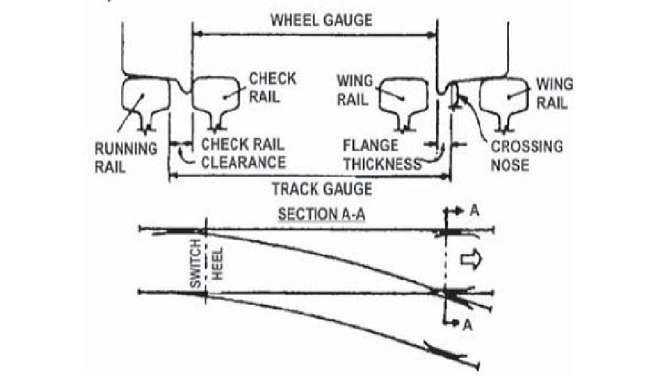
Crossing • Gaps to be provided in the track at this location for wheel flange to pass. • The flanges of wheel jump in this gap i. e from throat to Actual nose of crossing. • To guide wheel set so that it will nose is not hit with other wheel. • Check rails are provided opposite the nose of crossing.
Crossings n. Types – Built-up Crossing – Cast Manganese Steel (CMS) Crossing
Components / Features of Crossings • Key Components • • Vee Piece Wing Rails Point rail Splice rail Check rails Nose block & check rail block with bolts. Spherical washers/Tapered washers
Components / Features of Crossings • Vee piece it is made up of Point rail and splice rail bolted together. The thickness of nose of the vee piece is kept same as that of thickness of rail. • Wing rails: These are the two rails which starts from toe of crossing. Two wing rails called LH and RH converging to form a throat in front of nose of crossing and diverging on either ends. The wing rail are fixed to the vee piece in acute crossing. Wheel moves on wing rails upto ANC thereafter wheel load is progressively transferred to nose of crossing. • Nose blocks These are provided at nose of crossing to prevent vertical movement which takes place when wheel comes over the nose.
Components / Features of Crossings • Point rail : It is machined rail which extends upto ANC. Front end of point rail is machined but kept thick enough to take impact if any coming on it. Normally width of Point rail is kept equal to thickness of the corresponding rail. • Splice rail : It is the rail which forms part of nose of crossing but does not extend to ANC. It is connected to the point rail with the help of bolts. Point rail together with splice rail forms vee piece. In case of CMS crossing there is no concept of point or splice rail since it is monolithic.
Angle of Crossing
Important terms related to crossing • Theoretical Nose of Crossing (TNC) : It is an imaginary Point of intersection of two gauge lines of the vee piece when produced, intersect. This is used for calculations. • Actual Nose of Crossing (ANC) : It is the front pointed end of the point rail which is located at a point where the distance between the gauge lines of vee piece is equal to thickness of web of the rail is known as actual nose of crossing ( ANC ) The nose is tapered down by 6 mm in a length of 90 mm to avoid hitting of nose. • Throat of Crossing: Point where wing rails of crossing are the closest to each other
NUMBER OF CROSSING B 1 A N C • In triangle ABC A = TNC BC = 1 AC = N Angle A = crossing angle say ( F ) Angle C = 90° AC/BC = Cot F AC = BC Cot F = 1 Cot F = Cot F i. e; N = Cot F • Crossing are designated as 1 in N (N being the number of crossing) (N defined as N = cot F )
Check Rail at Crossing • Check rails are provided to • Prevent wheel flange from entering wrong groove; and • Prevent the wheel from striking the nose of crossing in facing direction • Provides lateral guidance to the wheel in the unguided gap between throat of crossing to ANC in the crossing area • Inside foot of check rail is planed • Ends of the check rail are flared to guide the wheel in gradually without knock
Check Rail at Crossing
Check Rail Function Direction of traffic
Check Rail 227. 5 1500 875 227. 5 1500 68. 75 41 1415 4330 Running Rail Gauge Face Check Rail
Check Rail Distance Blocks Three Piece Block X + 3. 15 mm
Check Rail Clearance c < G – g – tmax c < 1673 – 1600 – 28. 5 c < 44. 5 mm
Check Rail at Crossing • Check Rail Clearance = 1676 - 1600 - 28. 5 = 47. 5 mm ( max. ) Limits as per SOD 48 to 44 mm. (For Gauge 1673 mm - 45 to 41 mm) • Tighter clearance causes wear on check rail & slackness causes wheels to strike & wear down ANC
Thanks