MRPC Meeting 2020101 H Sako MRPC KK 5


")
 MRPC 1 -MRPC 2飛行時間とカット(I) MRPC 1 Strip")
 MRPC 1 -MRPC 2飛行時間とカット(II) MRPC 1 Strip")
 MRPC 1 -MRPC 2飛行時間とカット(I) MRPC 1 Strip")
 MRPC 1 -MRPC 2飛行時間とカット(II) MRPC 1 Strip")
 MRPC 1 -MRPC 2飛行時間とカット Vertex")


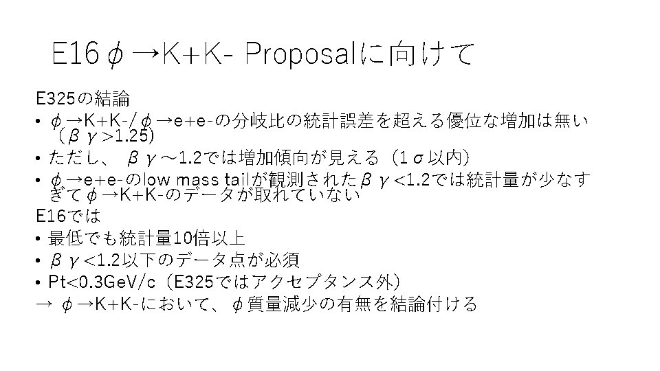
 f ee f KK")
 f ee f KK")


 (ns) TriggerにK候補のみカット")

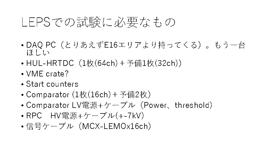
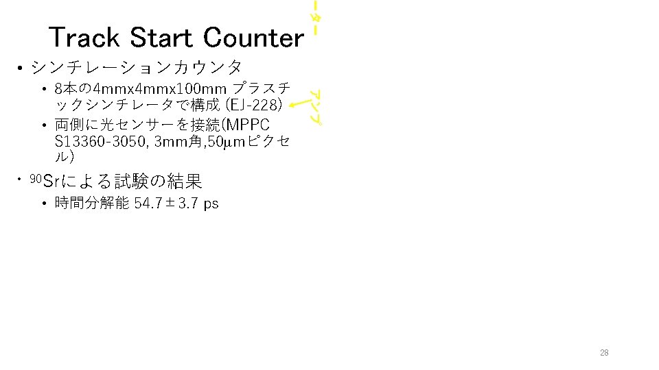
 • Forward trackers • MRPC, TSCのRate耐性")


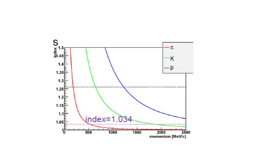
 HOD: RPC AC: index=1. 034 TOF: Scinti. +PMT 1 GEM-in GEM-mid")


 MRPC 1 Strip 3 – MRPC 2 Strip 3 1)")
 MRPC 1 Strip 3 – MRPC 2 Strip 3 3)")
 RPC 1 -RPC 2 hits TSC-RPC 1 -RPC 2")
 TSC-RPC 1 hits TSC-RPC 1 -RPC 2 hits 45")
 TSC-RPC 2 hits TSC-RPC 1 -RPC 2 hits 46")
")


のweighted meanで”clustering”")


 (mm/ns)= {155. 039, 148. 699, 144. 404, 149. 813, 150. 943, 153.")


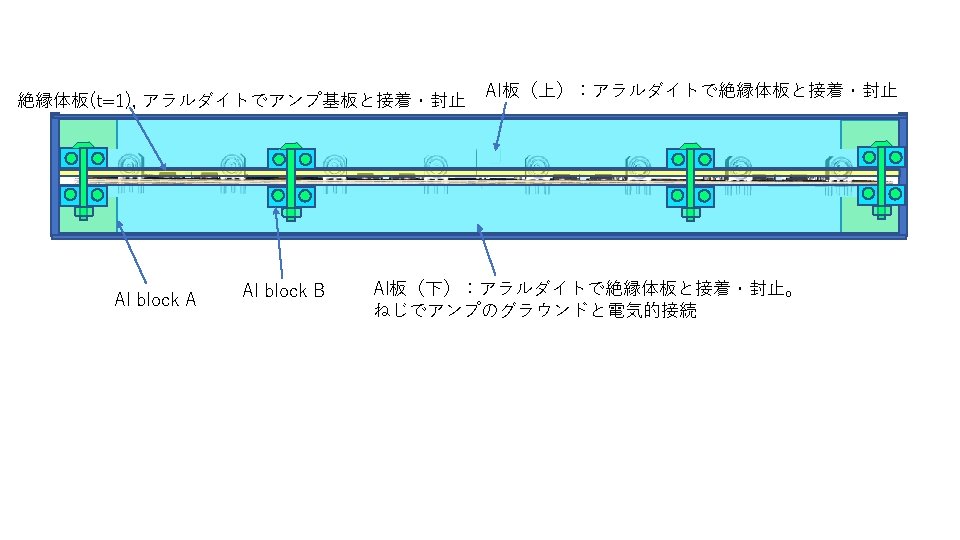
 Al chassis Connection betw. signal line of Amp")

 260 7 6 ~23 245 7 6 Honeycomb")


")


- Slides: 106
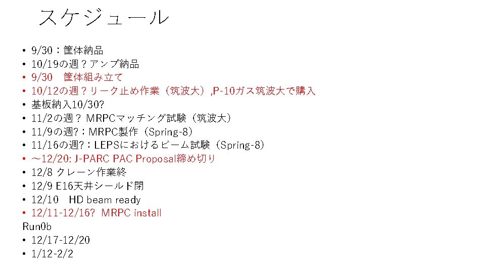
MRPC Meeting 2020/10/1 H. Sako スケジュール 各自報告 MRPC解析 Φ→KK
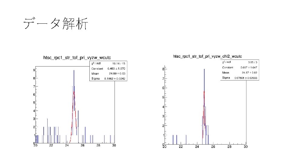
データ解析 5 x 10⁹/spill, B=0 (Run 2548)
Beam 1 x 10⁸/spill, B=0 (Run 2140) MRPC 1 -MRPC 2飛行時間とカット(I) MRPC 1 Strip 3 – MRPC 2 Strip 3 1) Vertex cut (RPC 1, RPC 2) 2) Vertex cut (RPC 1, RPC 2) Cross talk cut 7
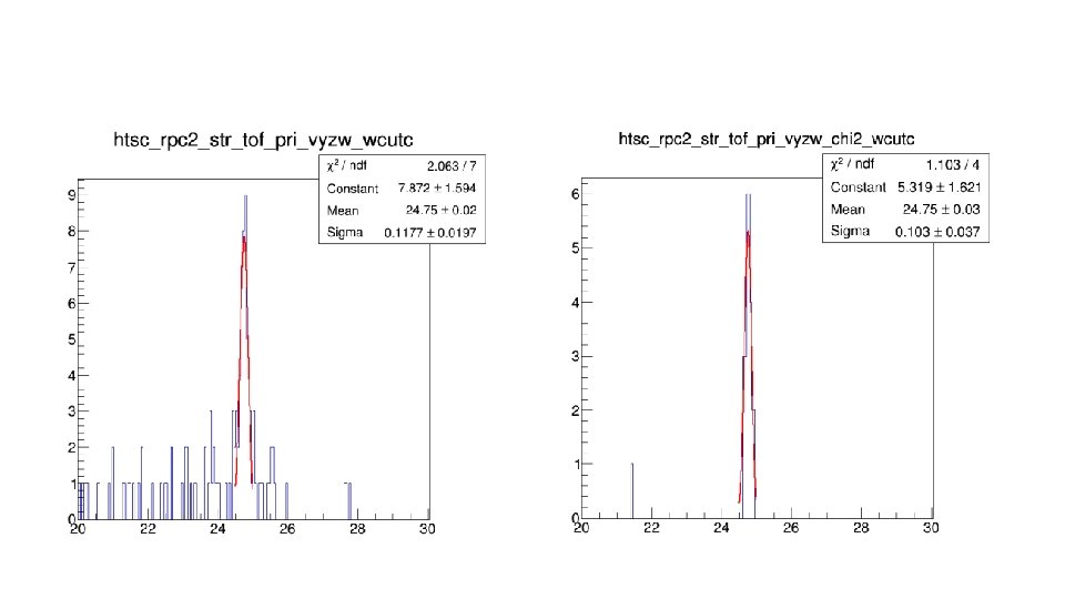
Beam 1 x 10⁸/spill, B=0 (Run 2140) MRPC 1 -MRPC 2飛行時間とカット(II) MRPC 1 Strip 3 – MRPC 2 Strip 3 3) Vertex cut (TSC, RPC 1, RPC 2) Cross talk cut 4) Vertex cut (TSC, RPC 1, RPC 2) Cross talk cut Slewing correction 5) Vertex cut (TSC, RPC 1, RPC 2) Cross talk cut Slewing correction Chi 2 cut (TSC-RPC 1 -RPC 2) 8
Beam 5 x 10⁹/spill, B=0 (Run 2548) MRPC 1 -MRPC 2飛行時間とカット(I) MRPC 1 Strip 3 – MRPC 2 Strip 3 1) Vertex cut (RPC 1, RPC 2) 2) Vertex cut (RPC 1, RPC 2) Cross talk cut 9
Beam 5 x 10⁹/spill, B=0 (Run 2548) MRPC 1 -MRPC 2飛行時間とカット(II) MRPC 1 Strip 3 – MRPC 2 Strip 3 3) Vertex cut (TSC, RPC 1, RPC 2) Cross talk cut 4) Vertex cut (TSC, RPC 1, RPC 2) Cross talk cut Slewing correction 5) Vertex cut (TSC, RPC 1, RPC 2) Cross talk cut Slewing correction Chi 2 cut (TSC-RPC 1 -RPC 2) 10
Beam 5 x 10⁹/spill, B=1. 95 T (Run 2517) MRPC 1 -MRPC 2飛行時間とカット Vertex 1) Vertex cut (RPC 1, RPC 2)
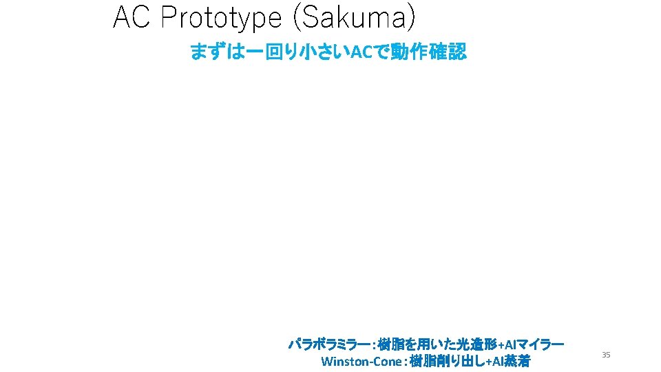
Study for Φ→KK Proposal. Top and bottom layers Middle layer FW-AC ± 7. 5 o FW-MRPC ± 7. 5 o FW-AC FW-MRPC AC TSC
1 4 45 2 15 4 3 45 2 3 15 45 f KK, w/ AC veto 15 45 p. T(Ge. V/c) p (Ge. V/c) f ee, Middle Layer, qzx=15 o-135 o 1 15 Y Y First Phase 2 nd Phase Y
1 Φのβγ 15 4 2 45 3 f ee, q=15 o-135 o 15 45 f KK, w/ AC veto bg bg
Middle layer thetax +-30 oを使用しない場合 1 1 4 2 3 45 15 15 45 4 2 3 15 45 15
E 325 setup
E 325 acceptance (Simulation, p+C) f ee f KK
E 325 acceptance (Data, p+C) f ee f KK
Kaon trigger at E 325 • 2 or more FTOF hits w/o associated AC hits • p>0. 4 Ge. V/c with HC-FTOF hit matrix • pion AC cutoff p<0. 5 Ge. V/c • TOF within Kaon window E 16では同様に • AC veto • TSC slat no. –MRPC strip no. , TOFを使用したtrigger でどの程度p, piをsuppressできるか?
P vs TOF w/AC w/o AC TOF p 21
Xrpc vs Xssd p+ K+ Xrpc Xssd p
Xrpc vs Xtsc x. RPC Slopeがフラットになるようにcorrection DRPC-SSD x. TSC
TOF vs DRPC-TSC DRPC-SSD TOF(RPC-TSC) (ns) TriggerにK候補のみカット
Invariant Mass E 325
Issues • 12/20にLOIを出したい • Configuration • TSCの設置位置(GTRの後ろは厳しい) • Forward trackers • MRPC, TSCのRate耐性
R=
E 325
Design (by Sakuma) HOD: RPC AC: index=1. 034 TOF: Scinti. +PMT 1 GEM-in GEM-mid GEM-out 15 4 2 AC HOD (=RPC) TOF (=Scinti) 45 3 15 45 1400へ 34
1 1 15 4 2 45 3 3 15 45 36
15 o
TOF vs DX Xrpc-Xssd TOF
Simulation • Timing resolution of single counter 41
MRPC 1 -MRPC 2飛行時間とカット(I) MRPC 1 Strip 3 – MRPC 2 Strip 3 1) Vertex cut (RPC 1, RPC 2) 2) Vertex cut (RPC 1, RPC 2) Cross talk cut 42
MRPC 1 -MRPC 2飛行時間とカット(II) MRPC 1 Strip 3 – MRPC 2 Strip 3 3) Vertex cut (TSC, RPC 1, RPC 2) Cross talk cut 4) Vertex cut (TSC, RPC 1, RPC 2) Cross talk cut Slewing correction 5) Vertex cut (TSC, RPC 1, RPC 2) Cross talk cut Slewing correction Chi 2 cut (TSC-RPC 1 -RPC 2) 43
Simulation (RPC 1 -RPC 2) RPC 1 -RPC 2 hits TSC-RPC 1 -RPC 2 hits 44
Simulation (TSC-RPC 1) TSC-RPC 1 hits TSC-RPC 1 -RPC 2 hits 45
Simulation (TSC-RPC 2) TSC-RPC 2 hits TSC-RPC 1 -RPC 2 hits 46
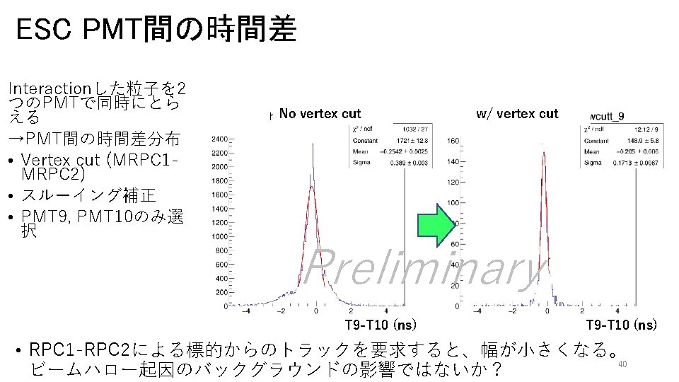
Slewing correction (ESC)
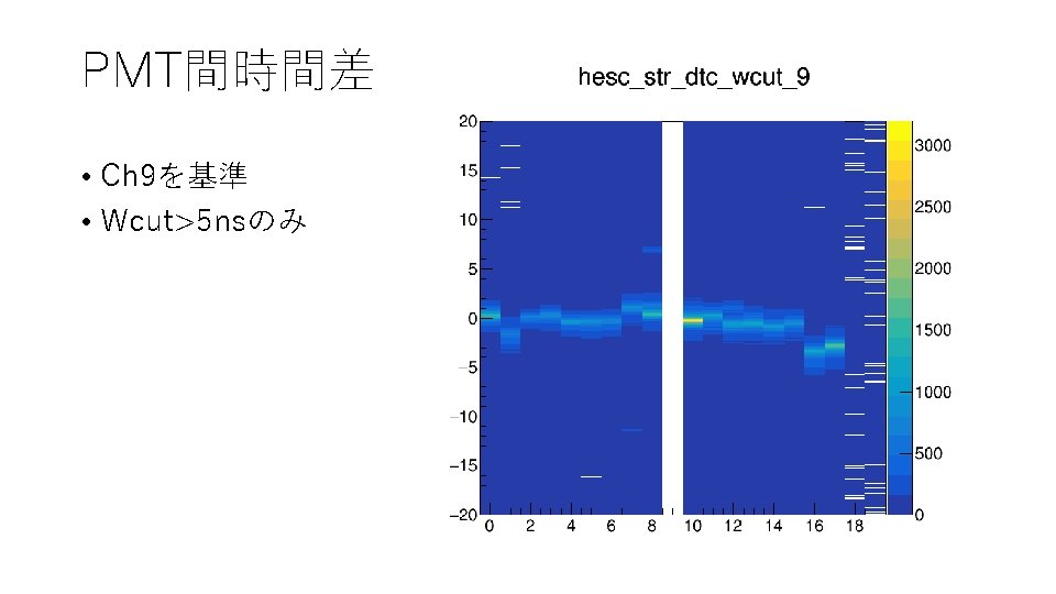
PMT間時間差 • Ch 9を基準 • Wcut>5 ns • vz, vy cut (RPC 1 -RPC 2)
PMT間時間差 • Ch 9を基 準 • Wcut>5 ns • Nhit PMT =0 >=6
Comparison with cuts • PMT 9 -10
Comparison with and w/o slewing cor • PMT 9 -10
Clusteringの試み • 2ヒットのみ、strip番号の差<=2のヒットの み(x, y, z)のweighted meanで”clustering”
RPC 1 TSC RPC 2 Strip # Slat #
RPC 1 RPC2 TSC
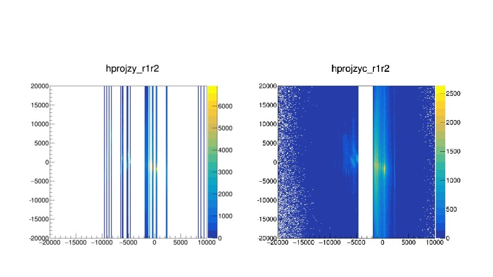
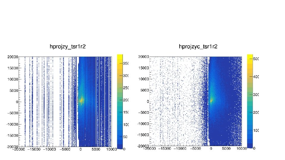
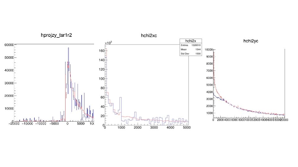
y-TSC Before calibration y-TSC Projected-y After calibration Projected-y
Chi 2 -y w/calibration
After calibration Projected z at X=0 plane Projected y at X=0 plane
v(RPC 1) (mm/ns)= {155. 039, 148. 699, 144. 404, 149. 813, 150. 943, 153. 257, 149. 813, 158. 103}; V(RPC 2) (mm/ns) = {153. 257, 162. 602, 145. 985, 149. 813, 144. 928, 147. 601, 143. 885, 153. 846}; V(TSC) (mm/ns) = {89. 8876, 79. 2079, 76. 1905, 79. 2079, 73. 3945, 72. 7273};
15 Generated 4 2 15 w/AC n=1. 034 4 2 3 3 No AC 45 45 15 45 45
Generated bg with AC n=1. 034 4 1 2 45 15 4 2 3 3 15 bg 1 15 45 45
1 15 4 2 3 15 45 45
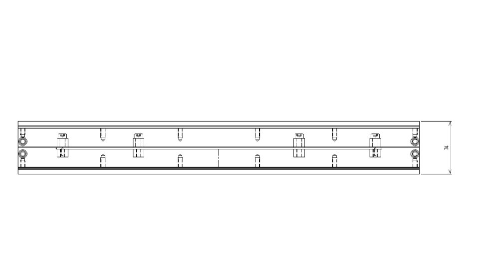
Dimension of E 16 PRC • Almost same structure as BGOegg-RPC but slightly shorter length HVケーブル用穴Φ 3 (全 2か所) 65 Total length=880 ガスフロー 260 65 φ3 Amp part lids can be opened (with O-rings) Space for amp =55 each Cathode PCB (230 x 770): 2 Anode PCB (230 x 770): 1 Honeycomb (6 x 240 x 750): 2 G-10 plate (0. 5 x 240 x 770): 4 Glass (0. 4 x 230 x 750): 12 Carbon tape (230 x 734) 83
893 853
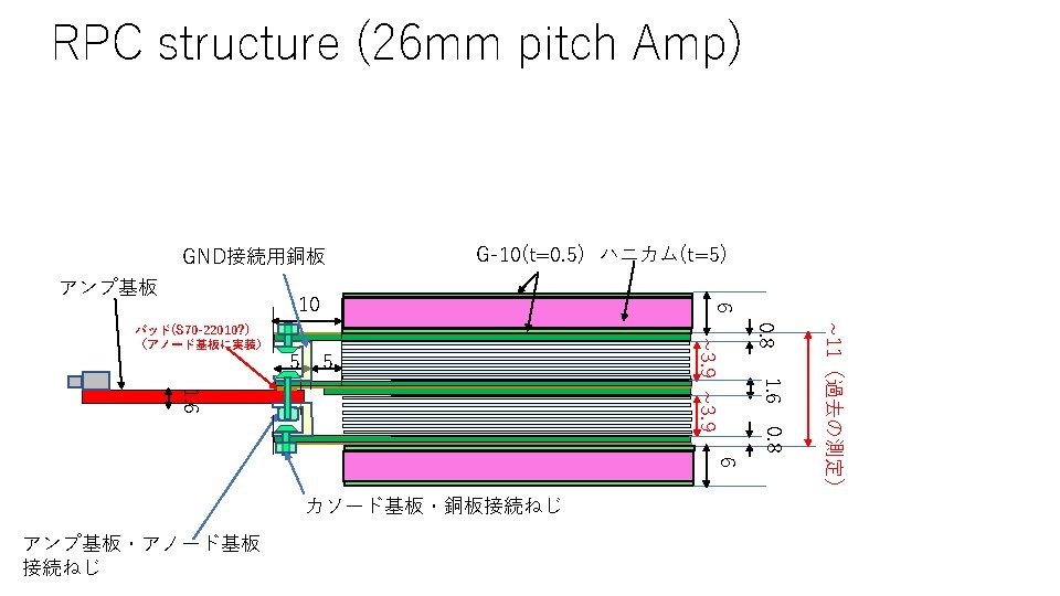
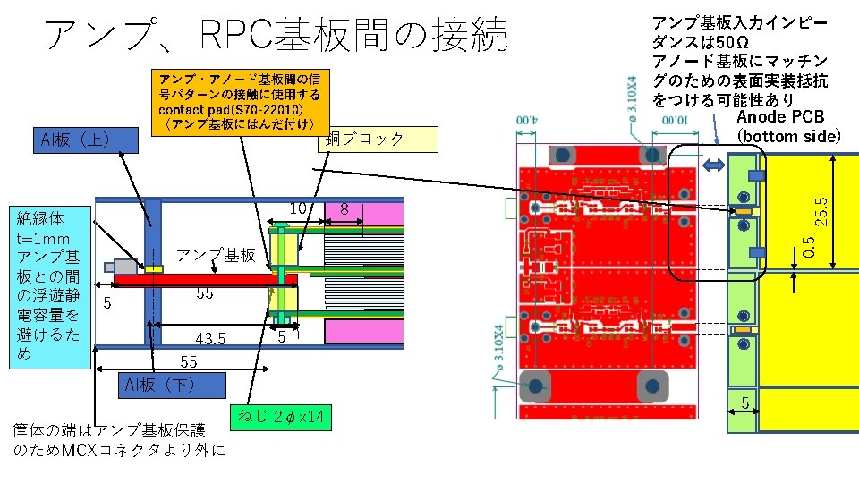
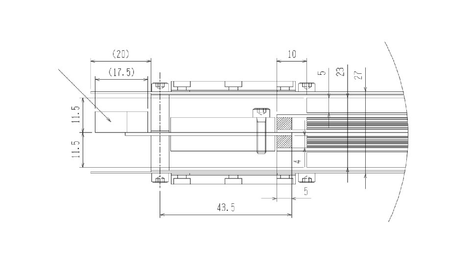
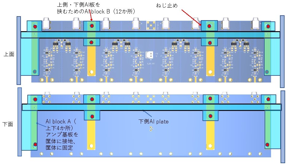
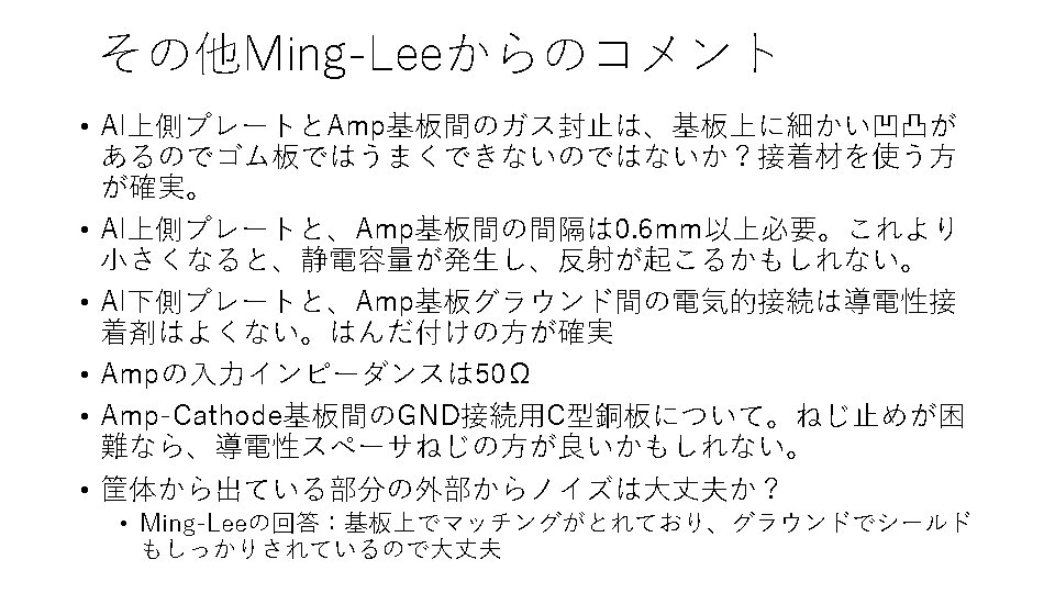
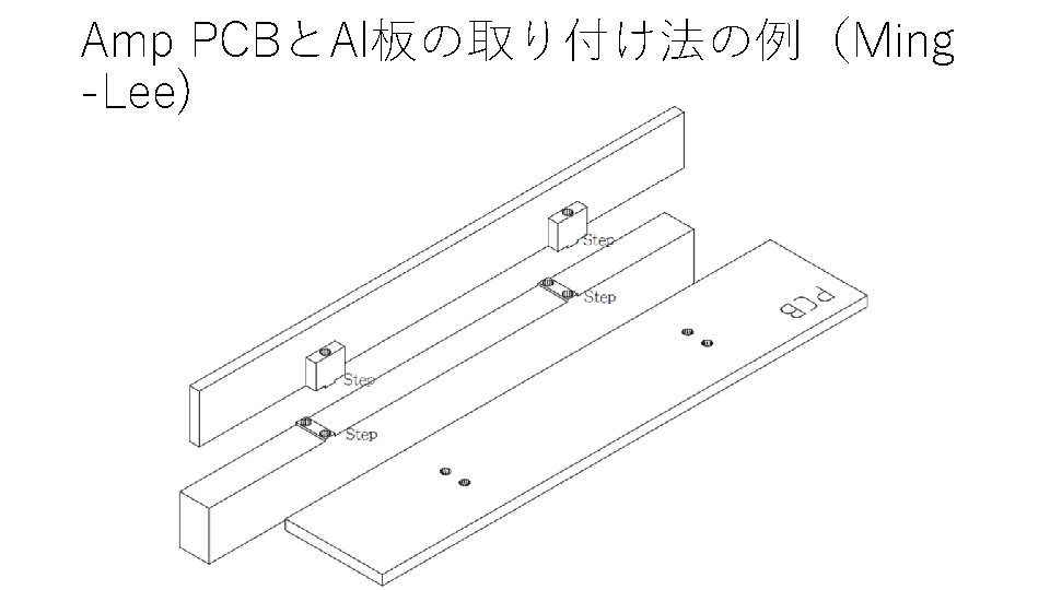
RPC structure (26 mm pitch Amp) Al chassis Connection betw. signal line of Amp PCB and RPC strip using contact pad(S 7022010) (soldered to anode PCB) Cu angle for GND connection between anode and cathode PCBs Same pattern of signal/ground as anode PCB for impedance matching (50Ω) Anode PCB (bottom side) 0. 5 25. 5 Glue for gas tightness Soldering or conductive glue between Amp PCB and chassis Amplifier PCB Screws through cathode PCBs, anode PCB, Amp PCB and Cu spacer Screw for electric contact between Amp PCB ground and Cu angle with 2. 1 mmf through holes 5
88
RPC断面 Honeycomb (t=5, 両側t=0. 5 G-10) 260 7 6 ~23 245 7 6 Honeycomb (t=5, 両側t=0. 5 G-10) 230 約11(ガラス+ Anode/cathod PCB) M 5 x 11? 樹脂製ねじ • 糸の張り方 89
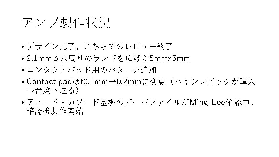
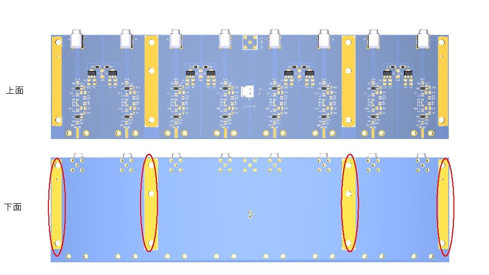
Request for 26 mm pitch amplifier 1. Make space w/o components and GND pattern in the bottom face between MCX and Lemo connector with 6 mm width Make pace w/o components In the same position in the top face 2. New 1. 1 mmf through holes for pins to determine the relative positions between the Al plates and the PCB. 3. Move two 3. 1 mmf through holes to the edge (~5 mm distance from the edge for example) 4. 5 4. Increase diameter of through holes φ1. 5 φ2. 1 Increase the distance from the center to 4. 5 mm We will not need these 4 through holes 91
92
Old New
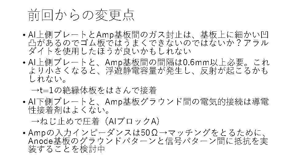
For Hayashi-REPIC (2020/8/19)
Dimension of E 16 PRC • Almost same structure as BGOegg-RPC but slightly shorter length HVケーブル用穴Φ 3 (全 2か所) 65 Total length=880 ガスフロー 260 65 φ3 Amp part lids can be opened (with O-rings) Space for amp =55 each Cathode PCB (230 x 770): 2 Anode PCB (230 x 770): 1 Honeycomb (6 x 240 x 750): 2 G-10 plate (0. 5 x 240 x 770): 4 Glass (0. 4 x 230 x 750): 12 Carbon tape (230 x 734) 100
19 Request of additional through holes We request two more 3. 1 mmφ through holes