ME 142 ENGINEERING DRAWING GRAPHICS PROJECTION METHOD LECTURE
")


 Drawing Advantage Easy to understand Disadvantage Shape and angle distortion Example Distortions")


- Slides: 28
ME 142 ENGINEERING DRAWING & GRAPHICS (PROJECTION METHOD)
LECTURE OBJECTIVES • • • Projection Method Orthographic projections Glass Box Approach First Angle Orthographic Projection Third Angle Orthographic Projection
PROJECTION METHOD Perspective Parallel Oblique Axonometric Orthographic Multiview
PROJECTION THEORY The projection theory is used to graphically represent 3 -D objects on 2 -D media (paper, computer screen). The projection theory is based on two variables: 1) Line of sight 2) Plane of projection (image plane or picture plane)
Line of sight is an imaginary ray of light between an observer’s eye and an object. There are 2 types of LOS : parallel and converge Parallel projection Perspective projection Line of sight
Plane of projection is an imaginary flat plane which the image is created. The image is produced by connecting the points where the LOS pierce the projection plane. Parallel projection Perspective projection Plane of projection
Disadvantage of Perspective Projection Perspective projection is not used by engineer for manufacturing of parts, because 1) It is difficult to create. 2) It does not reveal exact shape and size. Width is distorted
Orthographic Projection
MEANING Orthographic projection is a parallel projection technique in which the parallel lines of sight are perpendicular to the projection plane Object views from top 1 2 1 5 2 5 3 4 Projection plane 3 4
ORTHOGRAPHIC VIEW Orthographic view depends on relative position of the object to the line of sight. Rotate Two dimensions of an object is shown. More than one view is needed to represent the object. Multiview drawing Three dimensions of an object is shown. Axonometric drawing Tilt
ORTHOGRAPHIC VIEW NOTES Orthographic projection technique can produce either 1. Multiview drawing that each view show an object in two dimensions. 2. Axonometric drawing that show all three dimensions of an object in one view. Both drawing types are used in technical drawing for communication.
Axonometric (Isometric) Drawing Advantage Easy to understand Disadvantage Shape and angle distortion Example Distortions of shape and size in isometric drawing Circular hole becomes ellipse. Right angle becomes obtuse angle.
Multiview Drawing Advantage It represents accurate shape and size. Disadvantage Require practice in writing and reading. Example Multiviews drawing (2 -view drawing)
Orthographic Projections • Orthographic Projections are a collection of 2 -D drawings that work together to give an accurate overall representation of an object.
Defining the Six Principal Views or Orthographic Views
Which Views to Present? General Guidelines • Pick a Front View that is most descriptive of object • Normally the longest dimension is chosen as the width (or depth) • Most common combination of views is to use: – Front, Top, and Side View
Glass Box Approach • Place the object in a glass box • Freeze the view from each direction (each of the six sides of the box) and unfold the box
Glass Box Approach
Glass Box Approach
Glass Box Approach
Glass Box Approach
Glass Box Approach
Glass Box Approach
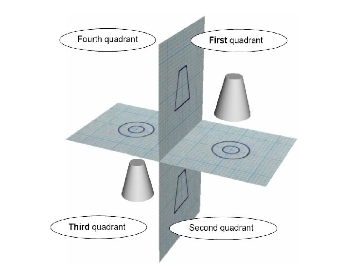
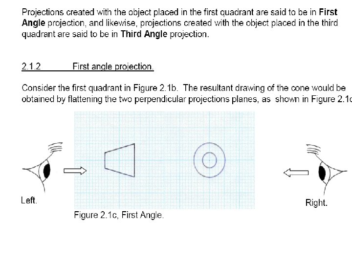
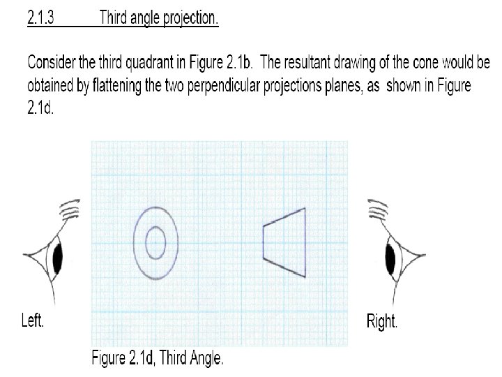
First and Third Angle Projections Third-angle Projection First-angle Projection • First Angle • Third Angle