Introduction to Embedded Systems Instructed by Iksan Bukhori

Introduction to Embedded Systems Instructed by: Iksan Bukhori
")
Outline • • Course Information Course Overview & Objectives Course Materials Course Requirement/Evaluation/Grading (REG)

I. Course Information • Instructor + Name : Iksan Bukhori + Address : Jl. Ki Hadjar Dewantara, President University, Cikarang, Bekasi : bukhoriiksan@gmail. com : + Email Address + Office Hours • Course‘s Meeting Time & Location + Meeting Time : Thursday-> 10. 30 – 13. 00 (Lec) + Location : Friday -> 10. 30 – 13. 00 (Lab) : Room B, President University, Cikarang Baru, Bekasi

Course Objectives The objectives of this course are students should be able to : • Demonstrate the understanding of several microprocessor architectures & organizations, bus systems, input/output units, and memory systems • Exhibit the ability in designing and building an interface for AVR ATmega 328 p microcontroller of an Arduino UNO Board • Develop interface programming using Assembly, or C languages • Assemble the interfacing of AVR ATmega 328 p microcontroller to other external peripherals, sensor(s) , actuator(s), computer(s)
 I II IV V VI Content Activity")
III. Course Materials Week (Tentative) I II IV V VI Content Activity
 VIII IX X XI XIII Final Exam : All Chapters/Activities")
Week Content Activity (Tentative) VIII IX X XI XIII Final Exam : All Chapters/Activities

IV. Course Requirement/Evaluation/Grading • Requirements : - Microcomputer Interfacing - Engineering Programming • Evaluation for the final grade will be based on : - Mid-Term Exam - Quizzes - Lab Experiments or Assignments - Course Project : 30 % : 15 % : 25 % : 30%

- Mid-Term Exam consists of Lectures given in between the Week 1 and the Week 6. - Final Exam covers whole subjects or materials given during the classes. § Grading Policy Final grades may be adjusted; however, you are guaranteed the following: If your final score is 85 - 100, your grade will be A. If your final score is 70 - 84, your grade will be B. If your final score is 60 - 69, your grade will be C. If your final score is 55 - 59, your grade will be D. If your final score is < 55, your grade will be E.

REFERENCES • LOTS

Rules & Regulations

Chapter 4 Sensor Interfacing Using Arduino

4. 1 Meet Arduino

4. 2 Sensors • Sensors are electronic devices that measure a physical quality such as light or temperature and convert it to a voltage. This process of changing one form of energy into another is called transduction. Often, sensors are also referred to as transducers. • Sensors can be broadly classified in two categories: digital sensors and analog sensors. A digital sensor's output can only be in one of two possible states. It is either ON (1) often +5 V, or OFF (0), 0 V. Most digital sensors work with a threshold. Is the incoming measurement below the threshold, the sensor will output one state, is it above threshold, the sensor will output the other state. • In contrast to a digital sensor, an analog sensor's output can assume any possible value in a given range. Very often the output of an analog sensor is a variable resistance that can be used to control a voltage. Rather than only being able to toggle between two states ( cf. a digital sensor) the analog sensor can output an almost infinite range of values.

4. 2. 1 Digital Sensor: Switch

Connecting Switch to Arduino

4. 2. 2 Serial Output • Eventually we would like the Arduino board to send sensor readings to a graphics application on the PC. This can be accomplished by using a communication strategy called “serial communication” to exchange the necessary data. In serial communication, data is transmitted one bit at a time over a single path. In order for the Arduino board and the host computer to understand each other, we need to work with a specific serial data protocol that defines e. g. communication speed (baud rate) and how to begin/end reading data.

4. 2. 2 Serial Output

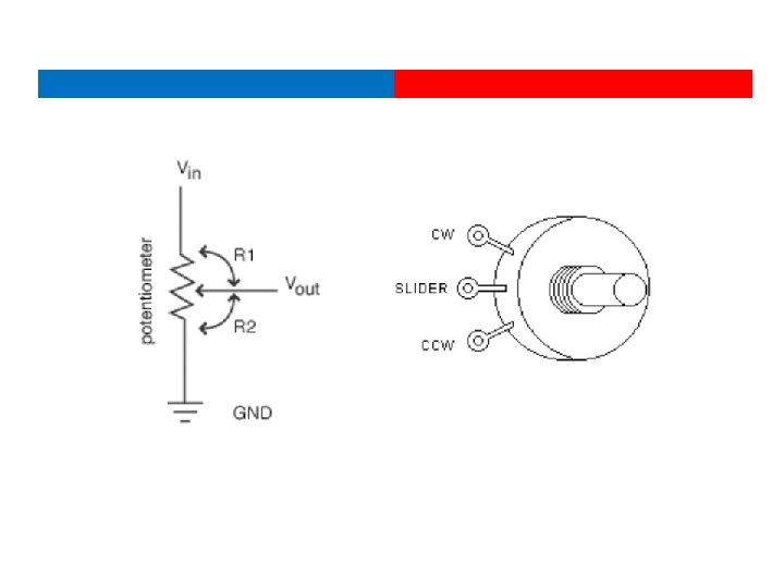
4. 2. 3 Analog Sensor: Potentiometer • Analog sensors, such as a photocell often work like a variable resistor the resistance of which is directly influenced by the condition it measures (in the case of the photocell it is the amount of light). Often a voltage divider circuit is used to turn the sensor’s changing resistance into a proportional change of voltage that can be understood better by ICs/microcontrollers (such as the Arduino) that you connect the sensor to. • In the circuit diagram on the right, potentiometer is used as a voltage divider, with its slider dividing the overall voltage into two parts R 1 and R 2. We see that a voltage divider produces a predictable fraction of the input voltage as the output voltage.

Connecting Potentiometer to Arduino • In this example we would like to connect a potentiometer to the Arduino and control the brightness of an external LED by turning the potentiometer’s knob. The Arduino board uses pulse width modulation (PWM) to dim the LED. In effect, the digital output is pulsed rapidly (turning the LED ON and OFF many times per second) to create the impression of the LED being evenly dimmed.

4. 3 Signal Conditioning What to do when the voltage range that a sensor provides and the range of an Arduino’s input pin don’t match up? • The interface of various sensors to a controller like the Arduino typically involves either conditioning or converting voltage levels into the range the controller requires. • Many systems use A/D converters to make the sensor value relevant in a program or data logging configuration. These converters have a fixed range of voltages they can convert from with 0 -5 V being by far the most common. • Sensors often create voltages in different ranges than those required by the controllers they are being interfaced to which requires the conversion of one voltage to another. This conversion often breaks down into a combination one or more of three types, amplification, dividing, and shifting.

4. 3. 1 Dividing Voltages For instance, say you have a sensor that outputs 0 -100 V and you want to convert this to 0 -5 V for interface to the A/D input on your Arduino. The goal would be to create a 20: 1 ratio of voltage which means dividing the original sensor output voltage by a factor of 20.

4. 3. 2 Amplifying Voltages • Voltage amplification is required for a class of sensors that create small voltages. • Often sensors of this type are converting some sort of physical energy such as acceleration, temperature, or other minimal physical force into a voltage. • This conversion is often an inefficient conversion and the measured energy is minimal which results in very small voltages generated by the sensor. • To make these small voltages meaningful, they must be amplified to a usable level.

4. 3. 2 Amplifying Voltages • Lets say you have an accelerometer which measures accelerations in g (gravity) units. • A sensor like this may have a response of 312 m. V/g which means the sensor will generate 0. 312 V for each gravity unit of force it encounters. • Now, say you would like to measure up to 2 gravity units (2 g) with your detector with the full range of your 0 -5 V A/D converter. • This means you need to multiply the output voltage of your accelerometer by a factor of about 16 to get the desired range and sensitivity in your measurements.

4. 3. 2 Amplifying Voltages

4. 3. 3 Shifting Voltages • Shifting voltages can be a requirement for sensor data that are generated symmetrically about a common (often ground) voltage. • A simple example of this would be a motor acting as a generator where spinning in one direction creates a positive voltage and spinning in the other direction creates a negative voltage. • Since most common A/D converters in microcontrollers deal with a 0 -Vcc range for conversions, sensors that are symmetric about the ground voltage reference need to be shifted into the 0 -Vcc range. • The equation for shifting is then the addition or subtraction of an offset from the original sensor's voltage. For example, if your sensor produces -2 to 2 V, you would want to add 2 V to the output for reading with a common 0 -5 V A/D converter. This addition would result in a final output of 0 -4 V which the A/D converter could then use

4. 3. 3 Shifting Voltages

4. 3. 4 Combining Conversions • Say you have a sensor that creates -100 to 100 V and you want to read the value with a 0 -5 V A/D converter. You would need to scale down the original voltage to -2. 5 to 2. 5 V first and then offset the result by adding 2. 5 V to get the result into the desired range of 0 -5 V for your A/D converter.

4. 3. 5 Conversion Impurities • The above conversions all introduce impurities in the resulting signal in the form of noise, non-linearity, and other corruptions of the original input voltage. • Care must be taken to minimize the number of stages and also to order them for reduced error. Testing and careful thought can typically reduce these impurities to a minimum but they cannot be disregarded. • There is a general rule of thumb with regard to these introduced impurities. The more you are changing the original voltage, the more impurities you will introduce. For instance, an amplification of 100 x would be generally noisier than one of 2 x.

4. 4 Sensor Examples: Temperature Sensor Voltage-based Resistance-based

4. 4. 1 TMP 36 These sensors use a solid-state technique to determine the temperature. That is to say, they don't use mercury (like old thermometers), bimetalic strips (like in some home thermometers or stoves), nor do they use thermistors (temperature sensitive resistors). • Instead, they use the fact as temperature increases, the voltage across a diode increases at a known rate. (Technically, this is actually the voltage drop between the base and emitter - the Vbe - of a transistor. ) • By precisely amplifying the voltage change, it is easy to generate an analog signal that is directly proportional to temperature. There have been some improvements on the technique but, essentially that is how temperature is measured. Because these sensors have no moving parts, they are precise, never wear out, don't need calibration, work under many environmental conditions, and are consistant between sensors and readings. Moreover they are very inexpensive and quite easy to use.

4. 4. 2 Temperature Measurement TMP 36 According to the TMP 36 datasheet, the relation of the output voltage to the actual temperature uses this equation: Where the voltage value is specified in millivolts. However, before you use that equation, you must convert the integer value that the analog. Read function returns into a millivolt value.

4. 4. 3 P 36 Code Sample

4. 4. 4 Thermistor The problem with resistance sensors is that the Arduino analog interfaces can’t directly detect resistance changes. This will require some extra electronic components. The easiest way to detect a change in resistance is to convert that change to a voltage change. You do that using a voltage divider, as shown below. By keeping the power source output constant, as the resistance of the sensor changes, the voltage divider circuit changes, and the output voltage changes. The size of resistor you need for the R 1 resistor depends on the resistance range generated by the sensor and how sensitive you want the output voltage to change. Generally, a value between 1 K and 10 K ohms works just fine to create a meaningful output voltage that you can detect in your Arduino analog input interface.

4. 4. 5 Thermistor Example

4. 5 Sensor Example: Range Sensor • Consists of two main parts, emitter which produces ultrasonic sound wave to the environment, and receiver which receives the reflected sound wave. Distance is calculated based on the time delay between emission and reception. • This sensor has four pins; VCC, GND, TRIG, and ECHO. User needs to control emission and reception of sound wave using the TRIG pin and ECHO Pin manually.

4. 5 HC-SR 04 Code Sample

Thank You
- Slides: 38