Lecture 6 OPTIC SOURCE LASER Iksan Bukhori M
 Iksan Bukhori, M. Phil.")
Lecture 6: OPTIC SOURCE (LASER) Iksan Bukhori, M. Phil.

LASER Light Amplification by Stimulated Emission of Radiation �The size of the laser source is from the size of a salt grain up to the size of the room. �Lasing media can be gas, liquid or solid. �For fiber optic systems, it is most suitable only for semiconductor laser diodes. �Radiation emission output is very monochromatic and directed.

Laser Emission

Main Process on Laser Emission

Laser Diodes � Laser action is the result of three key processes: photon absorption, spontaneous emission, and stimulated emission. � The processes are represented by the simple two – energy – level diagram in figure above, where is the ground state energy and is the excited state energy. a. According to Planck’s Law, a transition between these two states involves the absorption or emission of photon of energy b. Normally, the system is in the ground state.

� When a photon of energy impinges on the system, an electron in state can absorb the photon energy and be excited to state as shown in Figure (a). � Since this is an unstable state, the electron will shortly return to the ground state, thereby emitting a photon energy This occurs without any external stimulation and is called spontaneous emission. a. These emissions are isotropic and of random phase, and thus appear as a narrowband Gaussian output. � The electron can also be induced to make a downward transition from the excited level to the ground – state level by an external stimulation. a. As shown in Figure (c), if a photon energy impinges on the system while the electron is still in its excited state, the electron is immediately stimulated to drop to ground state and give off a photon energy b. This emitted photon is in phase with the incident photon, and the resultant emission is known as stimulated emission.

LASER DIODE MODE AND BOUNDARY CONDITIONS � Radiation in the laser diode occurs in the Fabry-Perot resonator space. � Long space size (longitudinal) 250 - 500 μm, width (lateral) 5 -15 μm thick (transverse) 0. 1 - 0. 2 μm. � Another type of laser diode is Distributed Feed. Back (DFB), it does not need a separate surface for optical feedback, but uses a Bragg reflector (grating) or a variation of the refractive index (distributed-feedback corrugation) on multilayer structures along the diode. � The dielectric reflector on the back side of the laser is used to reduce loss in the room, reduce threshold current density and increase external quantum efficiency.

Resonator Room

Resonator Fabry-Perot Room

Diode Laser DFB Struture

Laser diode mode and boundary conditions � � Optical radiation in the resonance chamber determines the pattern of the electric field and the magnetic field is called the mode of the cavity. Longitudinal mode: - Relates to the length of room L - Determine the spectrum of the frequency of optical radiation emitted - L> λ > 1 longitudinal mode. Lateral mode: - Located in the field of PN junctions - Depending on the side walls and width of the room - Determine the shape of the lateral profile of the laser beam Transverse mode: - Regarding the beam profile and the electromagnetic field in the direction perpendicular to the plane of the PN junction. - The mode determines laser characteristics such as radiation patterns and threshold current densities.

Laser diode mode and boundary conditions Lasing: A condition that allows light reinforcement. Terms of occurrence of lasing: there is an inverse population

Graph of optical output power and laser diode current

: External quantum differential efficiency external quantum differential efficiency the number of photons emitted by each radiative electron-hole recombination above threshold : internal quantum efficiency, the measurement results at room temperature is between 0. 6 - 0. 7 From experiment:

Resonance Frequency Steady state conditions if: Amplitude Phase If Then

The relation between reinforcement and wavelength can be assumed to be Gaussian: : wavelength in the center of the spectrum : width of the strengthening spectral : maximum gain is proportional to inverse population Distance between 2 adjacent frequencies: Distance between 2 adjacent wavelengths:

Ga. Al. As / Ga. As laser diode spectrum

Example �A Ga. As laser operating at 850 nm has a length and a refractive index n = 3. 7. What are the frequency and wavelength spacings? If, at the half power point, what is the spectral width of the gain?

Answer: � Using the formulas, � The half power point is formula � it yields by using the

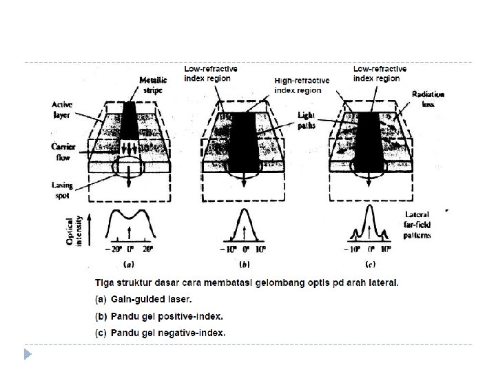
Laser diode structure and radiation patterns � How to limit optical waves: � Gain-guided, a narrow electrode band (<8μm) is placed along the diode � Index guided: 1) Positive index waveguide, the middle region has a higher index of refraction than the edge area all guided light is reflected in the dielectric boundary. Selection of the refractive index and the width of the high refractive index area will be able to produce a laser having only a fundamental lateral mode. 2) Negative - waveguide index, the middle region has a lower refractive index than the edge area some light is reflected and partially refracted out so that loss occurs.
")
�Index-guided, can be made using one of 4 basic structures: - Buried Heterostructure (BH) - Selectively diffused construction - Varying-thickness structure - Bent-layer configuration �In addition to limiting the optical wave to get a large optical output power is needed to tightly limit the runway current to the active layer so that more than 60% of the current contributes to the lasing process.

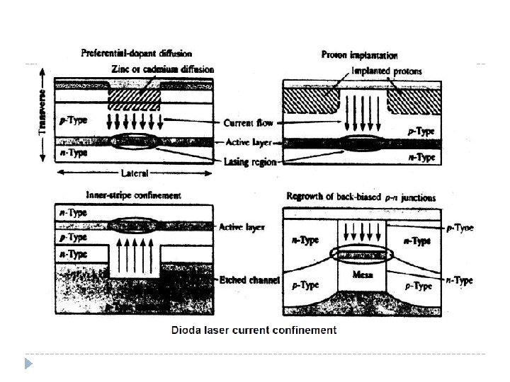
� 4 basic methods of current-confinement, each method holds the current on both sides of the lasing area, by means of the highresistivity area or the reverse voltage of the PN junction: - Preferential-dopant diffusion : - Proton implantation - Inner-stripe confinement - Regrowth of back-biased pn junction
 Ga. Al. As of short wavelengths (800 - 900")
Buried Heterostructure diode laser: (a) Ga. Al. As of short wavelengths (800 - 900 nm) (b) In. Ga. As. P long wavelength (1300 - 1600 nm)
 Selective diffused (b) Varying -")
Positive structure - optical index - wave confining (a) Selective diffused (b) Varying - thickness (c) Bent-layer
 Thin")
Active layer To get large output power can also be done by: (a) Thin - active - layer (TAL) (b) Large optical cavity (LOC)

Single-mode laser 1. Single laser mode, has a longitudinal live mode and a single transverse mode 2. To get a single longitudinal laser mode: - Reduces the wavelength of the Lasing space so that the frequency range ∆f is greater in the width of the laser transition line • For example the Fabry room - Perot L = 250μm, ∆λ = 1 nm, at λ = 1300 nm. If L becomes 25μm, then ∆λ = 10 nm. But making that length difficult. - Laser surface emission (SEL) - Structure that has a built-in frequency selective resonator

Structure of laser surface emission of GAAl. As

3 types of laser structure using built -in frequency selective resonator grating:

� Bragg wavelength: � Longitudinal mode is symmetrically separated around

The output spectrum is distributed around from the DFG laser diode

The nature of optical output power in temperature dependence

The diode laser transmitter construction uses a thermoelectric cooler for stabilization

Linearity of Light Sources Refractive point and amplitude modulation area on analog LED applications

Linearity of Light Sources The bias point and amplitude modulation region in the analog Laser application
- Slides: 36