EMBEDDED SYSTEMS An embedded system is a specialpurpose

EMBEDDED SYSTEMS

An embedded system is a special-purpose computer system designed to perform one or a few dedicated functions, often with realtime computing constraints. It is usually embedded as part of a complete device including hardware and mechanical parts. -- Wikipedia

Definition • Hard to define • Computing systems embedded within electronic devices • Nearly any computing system other than a desktop computer

Examples DVD player, Fax machine, Home security system, Photo copier, TV. . . etc. ,

History • In the earliest years of computers in 1930 – 40 s, computers were sometimes dedicated to a single purpose task. • First Mass-produced embedded system was the Autonetics D-17 guidance computer for the Minuteman missile, released in 1961. • One of the first recognizably modern embedded systems was the Apollo Guidance computer, developed by Charles stark draper at the MIT Instrumentation Laboratory.

History Conti. . . • In 1960's there is dramatic rise in power & functionality • The first microprocessor for example, the Intel 4004 was designed for calculators and other small systems but still required many external memory and support chips. • By the mid-1980 s, most of the common previously external system components had been integrated into the same chip as the processor and this modern form of the microcontroller allowed an even more widespread use, which by the end of the decade were the norm rather than the exception for almost all electronics devices
 Speed (bytes/sec) Accuracy (% error) Reliability Size & Weight")
Characteristics Adaptability Power dissipation (watts) Speed (bytes/sec) Accuracy (% error) Reliability Size & Weight

Classification Embedded Systems Functionality • • Stand-alone embedded systems -------Real-time embedded systems-----Hard real-time systems & Soft real-time system • • Networked embedded systems Mobile Embedded systems. Performance • • • Small scaled embedded system Medium scaled embedded system Large scaled embedded system.

Stand-alone Embedded systems : • Works by itself. It is a self-contained device which do not require any host system like a computer- EX : Temperature measurement systems, MP 3 players, digital cameras, and microwave ovens Real-time embedded systems : • • Gives the required output in a specified time (deadline). Soft Real-Time system: Violation of time constraints will cause only the degraded quality, but the system can continue to operate. EX: Washing machine , TV remote Hard Real-Time system : • Violation of time constraints will cause critical failure and loss of life or property damage or catastrophe. Ex: Deadline in a missile control embedded system , Delayed alarm during a Gas leakage , car airbag control system. Networked embedded systems : • Related to a network with network interfaces to access the resources. The connected network can be a LAN or a WAN, or the Internet. The connection can be either wired or wireless. EX : Home security system. Mobile Embedded systems • Mobile and cellular phones , digital camaras, MP 3 players, PDA. Limitation is Memory & other resources. Small scaled embedded system : Supported by a single 8– 16 bit Microcontroller with on-chip RAM and ROM. Medium scaled embedded system : Supported by 16– 32 bit Microcontroller /Microprocessor with external RAM and ROM. Large scaled embedded system: Supported by 32 -64 bit multiple chips which can perform distributed jobs.

Applications Home Appliances: Dishwasher, washing machine, microwave, Top-set box, security system , HVAC system, DVD, answering machine, garden sprinkler systems etc. . Office Automation: Fax, copy machine, smart phone system, modern, scanner, printers. Security : Face recognition, finger recognition, eye recognition, building security system , airport security system, alarm system. Academia : Smart board, smart room, OCR, calculator, smart cord. Instrumentation : Signal generator, signal processor, power supplier, Process instrumentation. Telecommunication : Router, hub, cellular phone, IP phone, web camera Automobile : Fuel injection controller, anti-locking brake system, air-bag system, GPS, cruise control. Entertainment MP 3, video game, Mind Storm, smart toy.

Applications Conti. . . Aerospace : Navigation system, automatic landing system, flight attitude controller, space explorer, space robotics. Industrial automation : Assembly line, data collection system, monitoring systems on pressure, voltage, current, temperature, hazard detecting system, industrial robot. Personal : PDA, smart phone, palmtop, data organizer. Medical : CT scanner, ECG , EEG , EMG , MRI, Glucose monitor, blood pressure monitor, medical diagnostic device. Banking & Finance : ATM, smart vendor machine, cash register , Share market Miscellaneous : Elevators, tread mill, smart card, security door etc.

Features • Designed to do some specific task • Not always standalone devices • Run with limited computer hardware resources: little memory, small or non-existent keyboard and/or screen. • Delivers maximum performance for minimum size and weight • Efficiency. • Reliability. • Works in real time constraints.

Architec ture

Components of Embedded Systems Hardware: Processor/controller, Timers, Interrupt controller, I/O Devices, Memories, Ports, etc Application Software : Which may perform concurrently the series of tasks or multiple tasks RTOS : RTOS defines the way the system work. Which supervise the application software. It sets the rules during the execution of the application program. A small scale embedded system may not need an RTOS.

Layered Architecture RTOS Application software Hardware

Hardware Architecture

Central Processing Unit CPU selection – 8, 16, 32, 64 CPU clock frequency -MHz Fetch , Decode , Execute

Memory Data Memory and Code Memory RAM - volatile ROM - non volatile EPROM Flash/EEPROM

eum n. N Vo vard Har ann Architectures
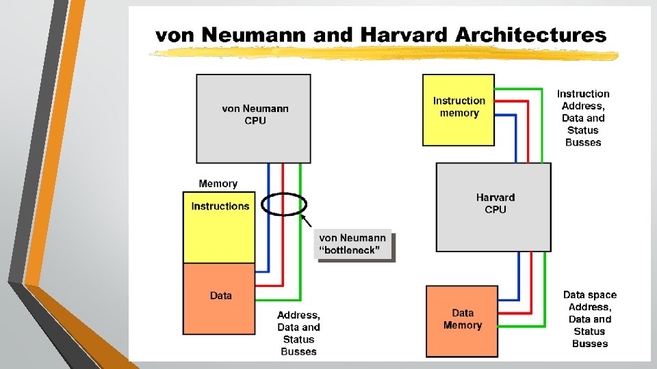

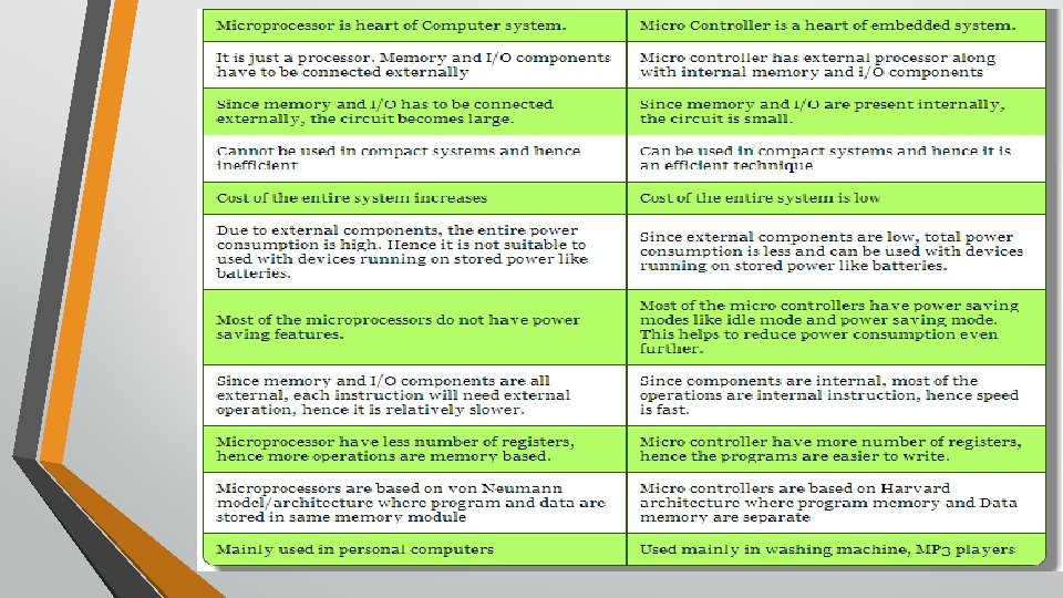
Von Neumann Harvard • John von Neumann • Single storage memory(data & • Harvard Mark 1 • Separate memories for storage & • Requires more memory cycles to • Requires less memory cycles to • Special “Table read” instructions is • Pipelining is not possible. • Less efficient. • Pipelining is possible with proper program). extract full instruction from memory. not needed. data. extract full instruction from memory. needed. strategies. • More efficient.

Tick-Tock, the Timer and the Clock What the heck is a timer? Timer is essentially a counter Clock inside/outside microcontroller Trigger interrupt when certain value is reached Ex-alarm 1 st Gen clocks-Hz/KHz 21 st cen clocks - GHZ How to choose best clock -Speed -Accuracy -Low power modes Timer intervals Flash an LED once a second fcry = 12 KHz – 12, 000 clock cycles/sec 0 x 2 EE 0 value need to be load in timer register Flash an LED once half a second What is the value need to load into timer register? 0 x 1770 Controlling the brightness of LEDs Control speed of motor. . etc

s & Add ress bu s Data bu Address Bus : Address bus is a part of the computer system bus that is dedicated for specifying a physical address. If width of the address bus is 32 bit then how many memory locations it will handle? 4, 294, 967, 296 Data Bus : A data bus simply carries data.

I/O Interfacing

Address Lines µp Data Lines Memory Control Lines Interface 26

µp Higher Address Bus A 15 – A 8 Lower Address/Data Bus AD 7 – AD 0 ALE READY 27

28

Demultiplexing Address/Data Lines Data 8085 AD 0 -AD 7 74 LS 373 A 0 – A 7 ALE Memory Chip Control A 8 -A 15 Memory Interface 29

Generating Control Signals =0 RD=0 WR=1 1 0 0 Memory Read Memory Write IO Read IO Write 30

Generating Control Signals =0 RD=1 WR=0 1 1 0 0 0 1 Memory Read Memory Write IO Read IO Write 31

Generating Control Signals =1 RD=0 WR=1 0 0 1 1 1 0 Memory Read Memory Write IO Read IO Write 32

Generating Control Signals =1 RD=1 WR=0 0 1 1 Memory Read Memory Write IO Read IO Write 33

8085 Interfacing with Memory chips Data 8085 AD 0 -AD 7 74 LS 373 A 0 – A 7 ALE A 8 -A 15 Memory A 8 -A 15 CS IO/M RD Program RD Memory Interface 34

Address decoders 2 to 4 decoder A 12 A 11 S 0 O 1 O 2 O 3 E A 13 A 10 - A 0 Memory 1 Memory 2 Memory 3 Memory 4 35

The Overall Picture A 15 - A 10 Chip Selection Circuit 8085 ALE AD 7 -AD 0 WR RD IO/M CS A 15 -A 8 Latch A 9 - A 0 A 7 - A 0 1 K Byte Memory Chip D 7 - D 0 RD WR 36

Continued…

Memory Mapped IO • IO is treated as memory. • 16 -bit addressing. • More Decoder Hardware. • Can address 216=64 k locations. • Less memory is available. IO Mapped IO • IO is treated IO. • 8 - bit addressing. • Less Decoder Hardware. • Can address 28=256 locations. • Whole memory address space is available. 38

Memory Mapped IO IO Mapped IO • Memory Instructions are used. • Memory control signals are used. • Arithmetic and logic operations can be performed on data. • Data transfer b/w register and IO. • Special Instructions are used like IN, OUT. • Special control signals are used. • Arithmetic and logic operations can not be performed on data. • Data transfer b/w accumulator and IO. 39
 • Single Operand(Format II) • Jumps")
Instruction Set Instruction format • Double Operand(Format I) • Single Operand(Format II) • Jumps 1. 2. 3. 4. Movement Instructions Arithmetic and Logic Instructions Shift and Rotate Instructions Flow of Control 27 Core instructions 24 emulated instructions which makes life easier for PROGRAMMER Instruction set is Orthogonal all addressing modes can be used with all instructions and registers.

Anatomy of an Instruction Opcode – What the instruction does – verb – May or may not require operands – objects Source Operand – 1 st data object manipulated by the instruction Destination Operand – 2 nd data object manipulated by the instruction – Also where results of operation are stored. Addressing Modes –

Instruction Format • There are three formats used to encode instructions for processing by the CPU core – Double operand – Single operand – Jumps • The instructions for double and single operands, depend on the suffix used, (. W) word or (. B) byte • These suffixes allow word or byte data access • If the suffix is ignored, the instruction processes word data by default
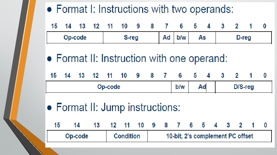

The source and destination of the data operated by an instruction are defined by the following fields: – src: source operand address, as defined in As and S-reg – dst: destination operand address, as defined in Ad and D-reg – As: addressing bits used to define the addressing mode used by the source operand – S-reg: register used by the source operand – Ad: Addressing bits used to define the addressing mode used by the destination operand – D-reg: register used by the destination operand – b/w: word or byte access definition bit.

Example l�Copy the contents of a register to another register – Assembly: mov. w r 5, r 4 – Instruction code: 0 x 4504 l�One word instruction l�The instruction instructs the CPU to copy the 16 -bit 2’s complement number in register r 5 to register r 4
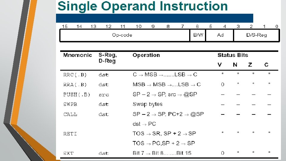

Example: Single Operand l�Logically shift the contents of register r 5 to the right through the status register carry – Assembly: rrc. w r 5 – Instruction code: 0 x 1005 l�One word instruction l�The CPU shifts the 16 -bit register r 5 one bit to the right (divide by 2) – the carry bit prior to the instruction becomes the MSB of the result while the LSB shifted out replaces the carry bit in the status register
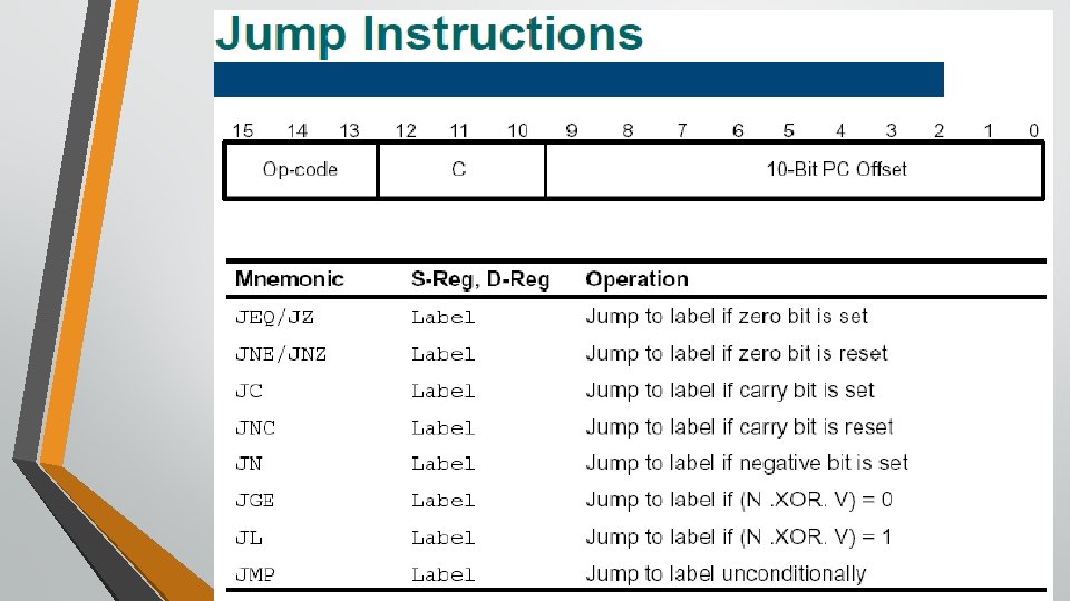

Jump instructions are used to direct program flow to another part of the program. l�The condition on which a jump occurs depends on the Condition field consisting of 3 bits: – 000: jump if not equal – 001: jump if equal – 010: jump if carry flag equal to zero – 011: jump if carry flag equal to one – 100: jump if negative (N = 1) – 101: jump if greater than or equal (N = V) – 110: jump if lower (N < V) – 111: unconditional jump

l�Jump instructions are executed based on the current PC and the status register l�Conditional jumps are controlled by the status bits l�Status bits are not changed by a jump instruction l�The jump off-set is represented by the 10 -bit, 2’s complement value: l�Thus, the range of the jump is -511 to +512 words, (-1022 to 1024 bytes ) from the current instruction l�Note: Use a BR instruction to jump to any address

Continue execution at the label main if the carry bit is set – Assembly: jc main – Instruction code: 0 x 2 fe 4 l�One word instruction l�The CPU will add to the PC (R 0) the value -28 x 2 if the carry is set
 push. w src ;")
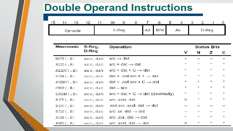
Movement Instructions mov. w src , dst ; move (copy) push. w src ; push data onto stack pop. w dst ; pop data off stack dst = src *--SP = src dst = *SP++ (emulated) Arithmetic and Logic Instructions Binary Arithmetic Instructions with Two Operands add. w src , dst ; addc. w src , dst ; adc. w dst ; sub. w src , dst ; subc. w src , dst ; sbc. w dst ; cmp. w src , dst ; add with carry add carry bit subtract with borrow subtract borrow bit compare , set flags only dst += src dst += (src + C) dst += C (emulated) dst -= src dst -= (src + ˜C) dst -= ˜C (emulated) (dst - src)

Arithmetic Instructions with One Operand clr. w dst ; decd. w dst ; incd. w dst ; tst. w dst ; clear decrement double decrement increment double increment test (compare with 0) dst = 0 dst -= 2 dst++ dst += 2 (dst - 0) emulated emulated Decimal Arithmetic dadd. w src , dst ; decimal add with carry dadc. w dst ; decimal add carry bit dst += src + C dst += C emulated

Logic Instructions with Two Operands and. w src , dst ; xor. w src , dst ; bit. w src , dst ; bis. w src , dst ; bic. w src , dst ; bitwise and bitwise exclusive or bitwise test , set flags only bit set bit clear dst &= src dst ˆ= src (dst & src) dst |= src dst &= ˜src Logic Instructions with One Operand inv. w dst ; invert bits dst = ˜dst Byte Manipulation swpb src ; sxt src ; swap upper and lower bytes (word only) extend sign of lower byte (word only) emulated

Operations on Bits in Status Register clrc ; clrn ; clrz ; setc ; setn ; setz ; dint ; eint ; clear carry bit C = 0 clear negative bit N = 0 clear zero bit Z = 0 set carry bit C = 1 set negative bit N = 1 set zero bit Z = 1 disable general interrupts GIE = 0 enable general interrupts GIE = 1 emulated emulated

Shift and Rotate Instructions Logical shift inserts zeroes for both right and left shifts. Arithmetic shift inserts zeroes for left shifts but the MSB, which carries the sign, is replicated for right shifts. Rotation does not introduce or lose any bits; bits that are moved out of one end of the register are passed around to the other. rla dst ; rra src ; rlc dst ; rrc src ; arithmetic shift left arithmetic shift right rotate left through carry rotate right through carry emulated

Flow of Control Subroutines, Interrupts, and Branches br src ; call src ; reti ; nop ; branch (go to) PC = src emulated call subroutine return from subroutine emulated return from interrupt no operation (consumes single cycle) emulated Jumps, Unconditional and Conditional jmp label ; unconditional jump jmp fits in a single word, including the offset, but its range is limited to about ± 1 KB from the current location. br can go anywhere in the address space and use any addressing mode but is slower and requires an extra word of program storage

jc label ; jump if carry set , C = 1 jnc label ; jump if carry not set , C = 0 jn label ; jump if negative , N = 1 jz label ; jump if zero , Z = 1 jnz label ; jump if nonzero , Z = 0 jeq label ; jump if equal , dst = src jne label ; jump if not equal , dst != src jhs label ; jump if higher or same , dst >= src jlo label ; jump if lower , dst < src jge label ; jump if greater or equal , dst >= src signed values jl(t) label ; jump if less than , dst < src signed values

tion Ti Instruc ming

Variants of MSP 430 family 3 xx 2 xx Category 5 xx Clock system Basic clock system + FLL, FLL+ Unified clock system(UCS) CPU, CPUXV 2 Security N/A CRC Communication USCI, USI USART, USCI, USB, RF DMA Up to 3 channel Up to 8 channel MPY 16, 32 MPY 32 Hardware multiplier MPY 16 Wakeup time from LPM 3 1µs 6µs 5µs Targeted Applications Metering, consumer & portable electronics, transportati on/automotive, military, space, avionics Metering, portable medical Test & measurement, USB, consumer & portable electronics, portable medical

Sample Embedded system on MSP 430 Full resistive bridge sensor MSP 430 MCU LCD
- Slides: 62