Electronic Circuits1CNET112 Level 4 th Department of CNET
 Level 4 th Department of CNET College of CS & IS Jazan")


")
 • Because the diode is only forward biased for one-half")


")


")


")


- Slides: 46
Electronic Circuits-1(CNET-112) Level 4 th Department of CNET College of CS & IS Jazan University KSA
CHAPTER -4 APPLICATIONS OF DIODE Objectives In this Chapter, student will learn the following topics: Ø Half Wave Rectifier Ø Peak Inverse Voltage Ø Center-Tapped Transformer Rectifier Ø Bridge Rectifier Ø Clippers (Biased & Parallel) and Clampers Ø Voltage-Multiplier Circuits (Voltage Tripler and Quadrupler)
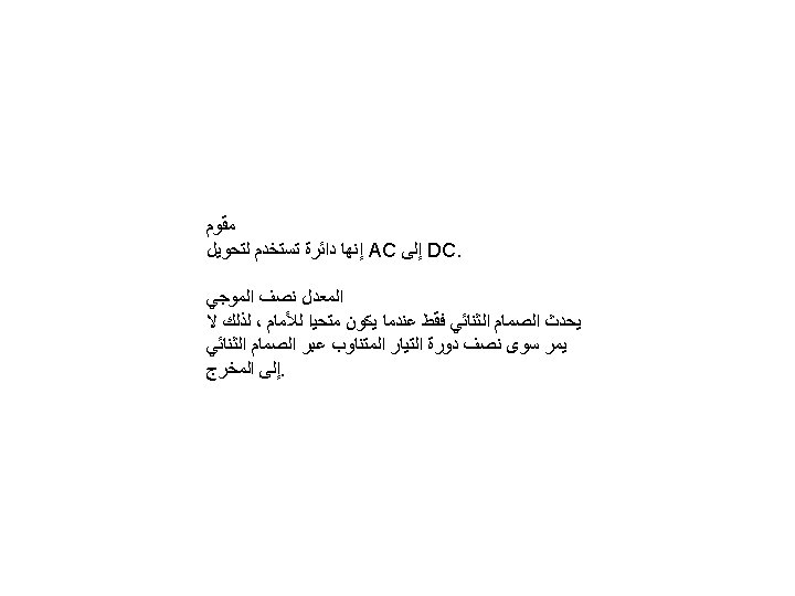
Rectifier It’s a circuit which is used to convert AC into DC. Half-Wave Rectifier The diode only conducts when it is forward biased, therefore only half of the AC cycle passes through the diode to the output.
The DC output voltage is 0. 318 Vm, where Vm = the peak AC voltage.
Half-Wave Rectifier
Half-Wave Rectifier (Video)
• PIV (PRV) • Because the diode is only forward biased for one-half of the AC cycle, it is also reverse biased for one-half cycle. • It is important that the reverse breakdown voltage rating of the diode be high enough to withstand the peak, reverse-biasing AC voltage. – PIV (or PRV) > Vm PIV = Peak inverse voltage PRV = Peak reverse voltage Vm = Peak AC voltage
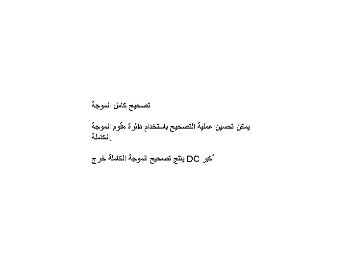
• Full-Wave Rectification • The rectification process can be improved by using a fullwave rectifier circuit. • Full-wave rectification produces a greater DC output: • • Half-wave: Vdc = 0. 318 Vm Full-wave: Vdc = 0. 636 Vm
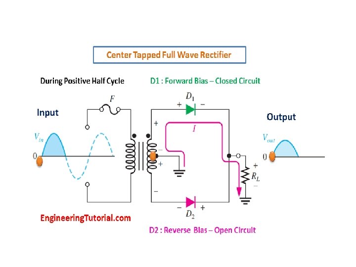
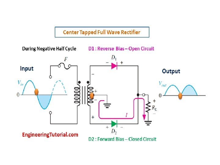
Full-Wave Rectification 1. Center-Tapped Transformer Rectifier • Requires • Two diodes • Center-tapped transformer • VDC = 0. 636 Vm
Full-Wave Rectification During Positive And Negative Cycle
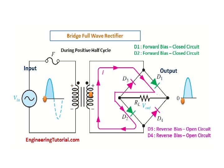
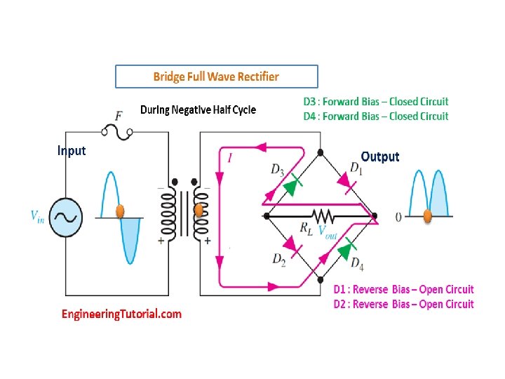
Full-Wave Rectification Bridge Rectifier • Four diodes are connected in a bridge configuration • VDC = 0. 636 Vm
Full-Wave Rectification During Positive And Negative Cycle
Bridge Rectifier (Video)
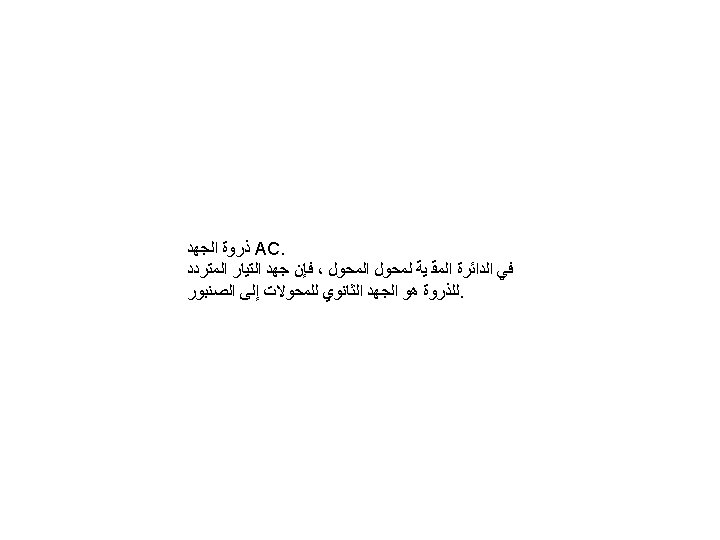
Summary of Rectifier Circuits Rectifier Ideal VDC Realistic VDC Half Wave Rectifier VDC = 0. 318 Vm – 0. 7 Bridge Rectifier VDC = 0. 636 Vm – 2(0. 7 V) Center-Tapped Transformer Rectifier VDC = 0. 636 Vm – 0. 7 V • Vm = peak of the AC voltage. • In the center tapped transformer rectifier circuit, the peak AC voltage is the transformer secondary voltage to the tap.
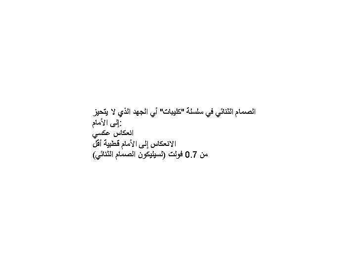
Diode Clippers • The diode in a series clipper “clips” any voltage that does not forward bias it: • A reverse-biasing polarity • A forward-biasing polarity less • than 0. 7 V (for a silicon diode)
Biased Clippers • Adding a DC source in series with the clipping diode changes the effective Forward bias of the diode.
Parallel Clippers • The diode in a parallel clipper circuit “clips” any voltage that forward bias it. • DC biasing can be added in series with the diode to change the clipping level.
Summary of Clipper Circuits
Summary of Clipper Circuits
Introduction To Clippers (Video)
Clampers A diode and capacitor can be combined to “clamp” an AC signal to a specific DC level.
Biased Clamper Circuits • The input signal can be any type of waveform such as sine, square, and triangle waves. • The DC source lets you • adjust the DC camping level.
Summary of Clamper Circuits
Introduction to Clampers (Video)
Voltage-Multiplier Circuits Voltage multiplier circuits use a combination of diodes and capacitors to step up the output voltage of rectifier circuits. • Voltage Doubler • Voltage Tripler • Voltage Quadrupler
Voltage Doubler This half-wave voltage doubler’s output can be calculated by: Vout = VC 2 = 2 Vm where Vm = peak secondary voltage of the transformer
Voltage Doubler • Positive Half-Cycle o D 1 conducts o D 2 is switched off o Capacitor C 1 charges to Vm • Negative Half-Cycle o D 1 is switched off o D 2 conducts o Capacitor C 2 charges to Vm Vout = VC 2 = 2 Vm
Voltage Tripler and Quadrupler
Voltage Multiplier Video
Practical Applications • Rectifier Circuits – Conversions of AC to DC for DC operated circuits – Battery Charging Circuits • Simple Diode Circuits – Protective Circuits against – Overcurrent – Polarity Reversal – Currents caused by an inductive kick in a relay circuit • Zenar Circuits – Overvoltage Protection – Setting Reference Voltages – Voltage regulator.
Queries