Electromagnetic NDT Veera Sundararaghavan Research at IITmadras 1


* H • Temperature Dependence: Eg.")


 Ñ 2(A) = -JS • Absolute/Differential Coil")
 & secondary (eddy current) fields.")


 Governing Equation: m- Permeability (Tesla-m/A), s- Conductivity (S), A -")
 Governing Equation : (1/m) Ñ 2(A) = -JS + jsw. A")
 Interpolation function: A(r, z, t) = [N(r,")
 = ( A(n+1)-A(n) ) / Dt A(1/2) = (A(n+1)+A(n)")
 Program Parameter Input Flux leakage Pattern")
 Differential Probe")


 = 2. 08796 x")


- Slides: 30
Electromagnetic NDT Veera Sundararaghavan
Research at IIT-madras 1. Axisymmetric Vector Potential based Finite Element Model for Conventional, Remote field and pulsed eddy current NDT methods. 2. Two dimensional Scalar Potential based Non Linear FEM for Magnetostatic leakage field Problem 3. Study of the effect of continuous wave laser irradiation on pulsed eddy current signal output. 4. Three dimensional eddy current solver module has been written for the World federation of NDE Centers’ Benchmark problem. The solver can be plugged inside standard FEM preprocessors. 5. FEM based eddy current (absolute probe) inversion for flat geometries. Inversion process is used to find the conductivity profiles along the depth of the specimen.
Electromagnetic Quantities E – Electric Field Intensity Volts/m H – Magnetic Field Intensity Amperes/m D – Electric Flux density Coulombs/m 2 B – Magnetic Flux density Webers/m 2 J – Current density Amperes/m 2 r-Charge density Coulombs/m 3 m-Permeability e-Permittivity s-Conductivity - B/H - D/E - J/E
Classical Electromagnetics Maxwell's equations Ñ x H = J + d. D / dt Ñ x E = - d. B / dt Ñ. B = 0 Ñ. D = r Constitutive relations B = m. H D = e. E J = s. E Ampere’s law Faraday’s law Magnetostatic law Gauss’ law
Interface Conditions • E 1 t = E 2 t • D 1 n-D 2 n = ri • H 1 t-H 2 t = Ji • B 1 n = B 2 n 1 2 Boundary conditions • Absorption Boundary Condition - Reflections are eliminated by dissipating energy • Radiation Boundary Condition – Avoids Reflection by radiating energy outwards
Material Properties • Field Dependence: eg. B = m(H)* H • Temperature Dependence: Eg. Conductivity Material Classification 1. Dielectrics 2. Magnetic Materials - 3 groups • Diamagnetic (m < 1) • Paramagnetic (m >= 1) • Ferromagnetic (m >> 1)
Potential Functions Scalar: If the curl of a vector quantity is zero, the quantity can be represented by the gradient of a scalar potential. Examples: Ñ x E = 0 => E = - ÑV Vector: If the field is solenoidal or divergence free, then the field can be represented by the curl of a vector potential. Examples: Primarily used in time varying field computations Ñ. B = 0 => B = Ñ x A
Derivation of Eddy Current Equation Magnetic Vector Potential : B = Ñx. A Ñx E = - d. B / dt => Faraday’s Law Ñx E = - Ñx d. A / dt => E = - d. A / dt - ÑV J = s. E => J = - s d. A / dt + JS => at low frequencies (f < 5 MHz) displacement current (d. D / dt) = 0 Ampere’s Law: Ñ x H = J + d. D / dt Assumption 1: H = B/m => Assumption 2 : Final Expression: => H = Ñx. A/ m Ñ. A = 0 (Continuity criteria) (1/m) Ñ 2(A) = -JS + s(d. A /dt)
Electromagnetic NDT Methods • Leakage Fields (1/m) Ñ 2(A) = -JS • Absolute/Differential Coil EC & Remote Field EC (1/m) Ñ 2(A) = -JS + jsw. A • Pulsed EC & Pulsed Remote Field EC (1/m) Ñ 2(A) = -JS + s(d. A /dt)
Principles of EC Testing Opposition between the primary (coil) & secondary (eddy current) fields. In the presence of a defect, Resistance decreases and Inductance increases.
Differential Coil Probe in Nuclear steam generator tubes
Pulsed EC
FEM Forward Model (Axisymmetric) Governing Equation: m- Permeability (Tesla-m/A), s- Conductivity (S), A - magnetic potential (Tesla-m), w - the frequency of excitation (Hz), Js – current density (A/m 2) z rm Energy Functional: zm d. F(A)/d. Ai = 0 ------ Final Matrix Equation Triangular element r
FEM Formulation(3 D) Governing Equation : (1/m) Ñ 2(A) = -JS + jsw. A 5 6 8 7 1 3 4 3 1 F(A) = ò (0. 5 ni. Bi 2 – Ji. Ai + 0. 5 jws. Ai 2)d. V, i = 1, 2, 3 2 4 Energy Functional No. of Unknowns at each node : Ax, Ay, Az No. of Unknowns per element : 8 x 3 = 24 Energy minimization d. F(A)/d. Aik = 0, k = x, y, z For a Hex element yields 24 equations, each with 24 unknowns. 2 Final Equation after assembly of element matrices Solid Elements: Magnetic Potential, [K][A] = [Q] where [K] is the complex stiffness matrix and [Q] is the source matrix A = SNi. Ai
Derivation of the Matrix Equation(transient eddy current) Interpolation function: A(r, z, t) = [N(r, z)][A(t)]e [S][A] + [C][A’] = [Q] where, [S]e = ò (1/m) [DN]T[DN] dv [C]e = ò s [DN]T[DN] dv [Q]e = ò Js[DN]Tdv
Time Discretisation Crank-Nicholson method A’(n+1/2) = ( A(n+1)-A(n) ) / Dt A(1/2) = (A(n+1)+A(n) ) / 2 substituting in the matrix equation [C] + [S] [A]n+1 = [Q] + [C] - [S] [A]n Dt 2
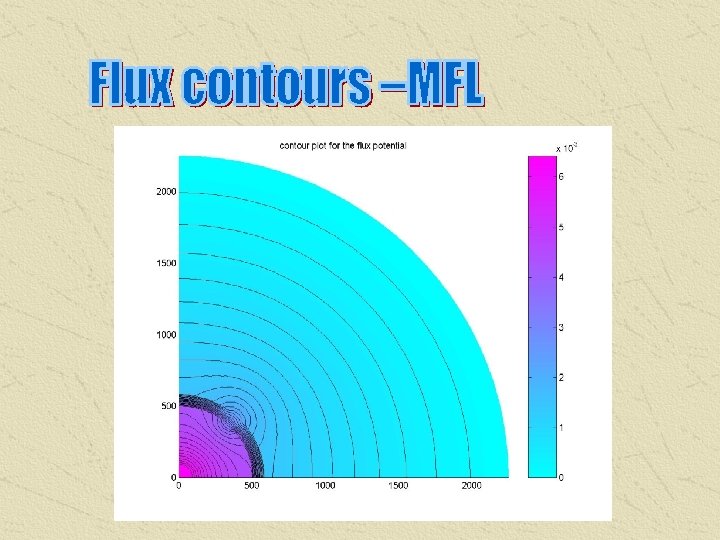
2 D-MFL (Non-linear) Program Parameter Input Flux leakage Pattern
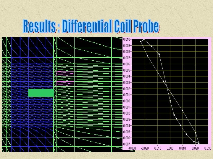
Absolute Probe (Diff. Pack) Differential Probe
Reluctance = 1 Reluctance = 200 Reluctance = 40 Reluctance = 20
L = 1 mm L = 2 mm L = 3 mm L = 4 mm Increasing lift off
1 4 3 2 2 1 3 4
Pulsed Eddy Current : Diffusion Process Input : square pulse (0. 5 ms time period) Total time : 2 ms
Results : Transient Equation Input current density v/s time step Gaussian Input Output voltage of the coil
Validation – 3 D ECT problem L (3 D model) = 2. 08796 x 10 -4 H L (Axi-symmetric model) = 2. 09670 x 10 -4 H Error = 0. 42 % Axisymmetric mesh (left) and the 3 D meshed model(right)
Eddy Current WFNDEC Benchmark Problem
Benchmark Problem