
BMFB 4283 NDT FAILURE ANALYSIS Lectures for Week
BMFB 4283 NDT & FAILURE ANALYSIS Lectures for Week 8 Prof. Qumrul Ahsan, Ph. D Department of Engineering Materials Faculty of Manufacturing Engineering
Failure Analysis 8. Introduction to Failure Analysis 8. 0 Objective of failure analysis. 8. 1 Approach to failure analysis 8. 2 Tools of Failure Analysis 8. 3 Failure Mode and Effect Analysis (FMEA)
Outline of Failure Analysis • Vast topic, many failure modes and mechanisms, overlap, disputes • Always exceptions • Focus on: – Failure analysis process – Some common failures • Highlight some interesting failures • Primarily steel, but present in most materials
Objectives of Failure Analysis • Objective investigation of material facts associated with a part or system failure – To understand the failure mechanism of the failed component – To determine the primary/root cause of the failure – To recommend the corrective actions • Determine: – Timeline, chain of events – Root-cause of incident / contributing factors – Post incident fitness for purpose – Repair options – Mitigating future failures
What is failure? • Part and/or system no longer complies with design intent for part or system • Subjective definition based on operation • Not always structural – – – Leaking hydraulic seals Inappropriate stiffness in component Rate of corrosive decay/breakdown Part/system lifetime Operating/maintenance costs Aesthetics • Any design parameter
Facts of Failures • Manifestation of failure (elastic & plastic deformation, rupture or fracture, change of metals) • Failure inducing agent (force, time, temperature, reactive environment) • Failure locations (body type, surface type) • Failure Mode (ductile, brittle, fatigue, creep, wear, weld etc)
Where to Apply • Industrial / Manufacturing – Manufacturing equipment (presses, fixtures) • Consumer Products – Design improvement, validation • Civil Structures / Infrastructure – Structural stability – Utilities (inspection, testing, failure analysis) • Insurance / Legal cases – Root cause, forensics
Tools of the Trade • Instrumentation – Strain gage, accelerometer, data acquisition • Inspection – NDT, weld inspection, cracking, corrosion • Analysis – Failure analysis, Fitness for purpose, Stress analysis, Finite Element Analysis (FEA), Metallurgical • Testing – Load testing, cycle testing, instrumented tests, impact test, tensile test
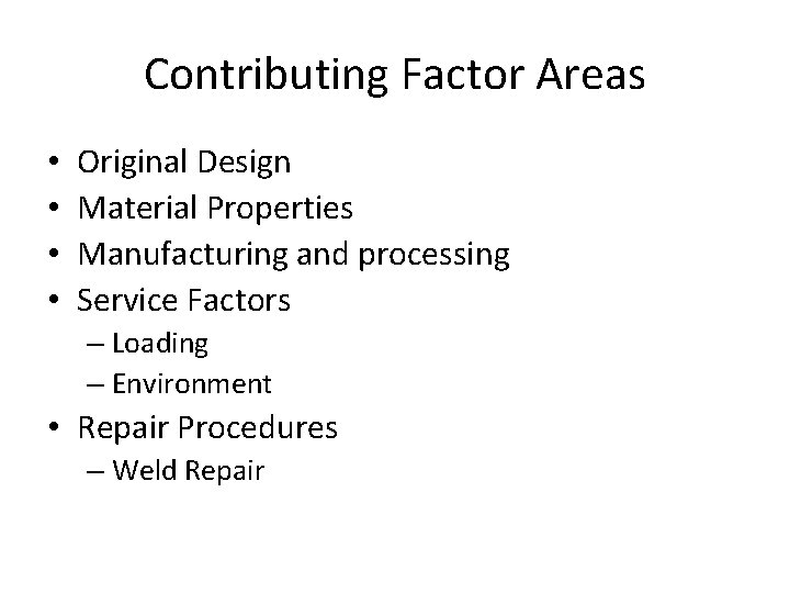
Contributing Factor Areas • • Original Design Material Properties Manufacturing and processing Service Factors – Loading – Environment • Repair Procedures – Weld Repair
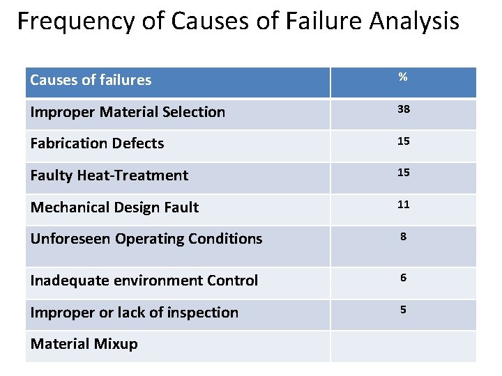
Frequency of Causes of Failure Analysis Causes of failures % Improper Material Selection 38 Fabrication Defects 15 Faulty Heat-Treatment 15 Mechanical Design Fault 11 Unforeseen Operating Conditions 8 Inadequate environment Control 6 Improper or lack of inspection 5 Material Mixup
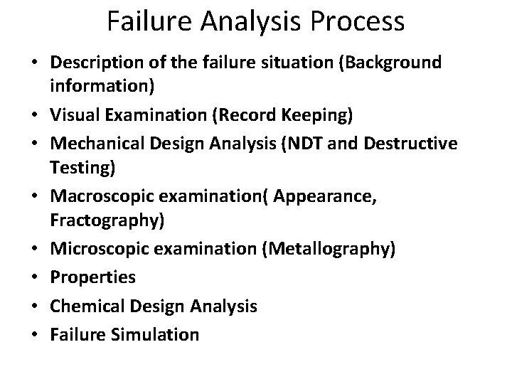
Failure Analysis Process • Description of the failure situation (Background information) • Visual Examination (Record Keeping) • Mechanical Design Analysis (NDT and Destructive Testing) • Macroscopic examination( Appearance, Fractography) • Microscopic examination (Metallography) • Properties • Chemical Design Analysis • Failure Simulation
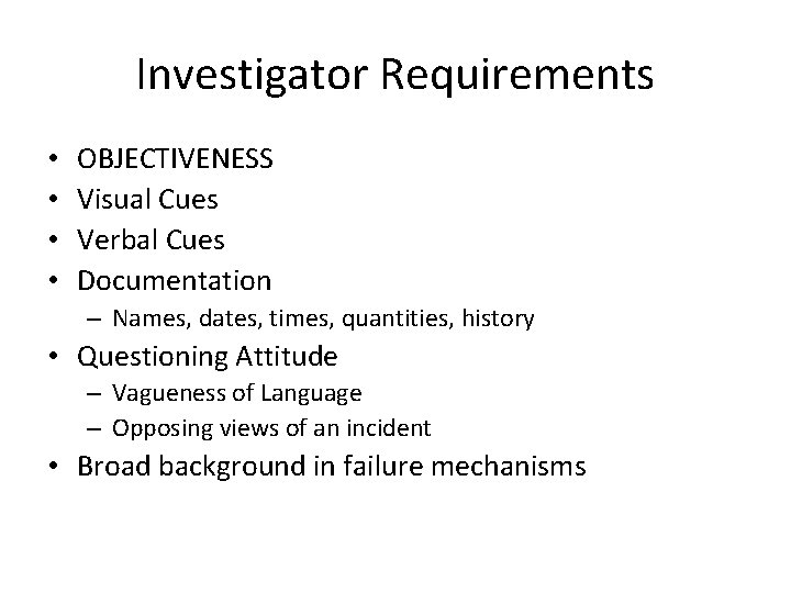
Investigator Requirements • • OBJECTIVENESS Visual Cues Verbal Cues Documentation – Names, dates, times, quantities, history • Questioning Attitude – Vagueness of Language – Opposing views of an incident • Broad background in failure mechanisms
Technological Tools • Photography and lighting • Optical Microscopy up to 600 X • Scanning Electron Microscopy (SEM) over 10, 000 X • Chemical Analysis – SEM/EDS – Spark Emission Spectroscopy – Fourier Transform Infra Red (FTIR)
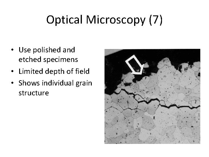
Optical Microscopy (7) • Use polished and etched specimens • Limited depth of field • Shows individual grain structure
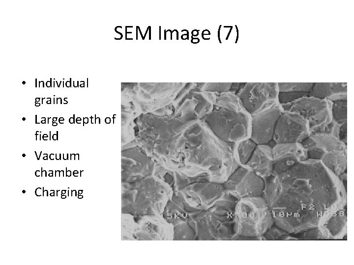
SEM Image (7) • Individual grains • Large depth of field • Vacuum chamber • Charging
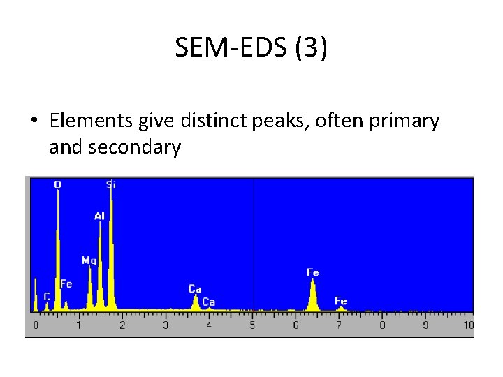
SEM-EDS (3) • Elements give distinct peaks, often primary and secondary
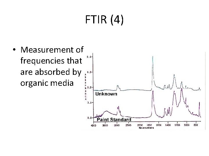
FTIR (4) • Measurement of frequencies that are absorbed by organic media
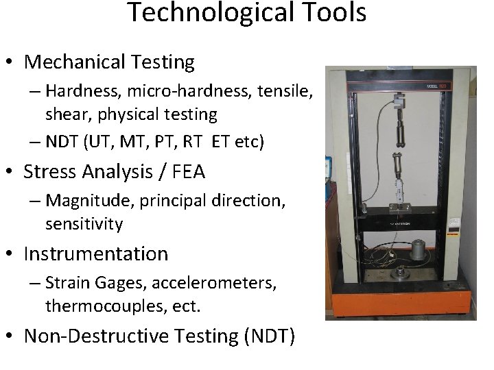
Technological Tools • Mechanical Testing – Hardness, micro-hardness, tensile, shear, physical testing – NDT (UT, MT, PT, RT ET etc) • Stress Analysis / FEA – Magnitude, principal direction, sensitivity • Instrumentation – Strain Gages, accelerometers, thermocouples, ect. • Non-Destructive Testing (NDT)
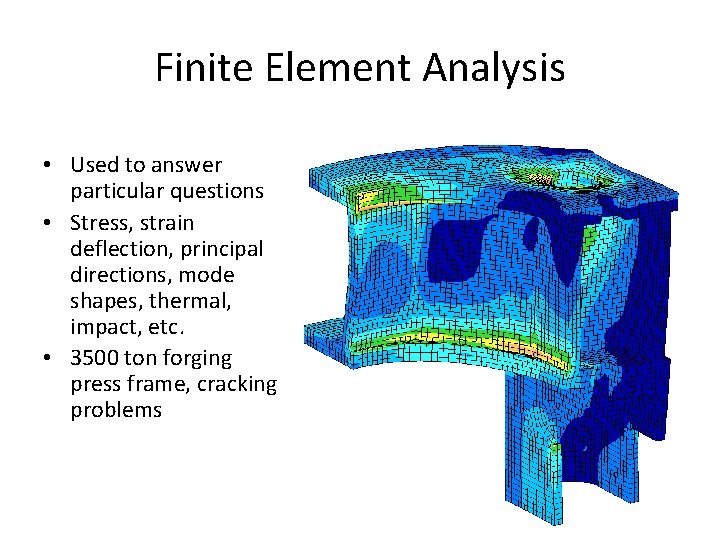
Finite Element Analysis • Used to answer particular questions • Stress, strain deflection, principal directions, mode shapes, thermal, impact, etc. • 3500 ton forging press frame, cracking problems
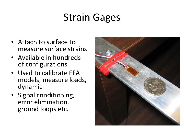
Strain Gages • Attach to surface to measure surface strains • Available in hundreds of configurations • Used to calibrate FEA models, measure loads, dynamic • Signal conditioning, error elimination, ground loops etc.
ASM Failure Analysis American Society of Metals (ASM) outline Experts in each area Remain OBJECTIVE Important to be thorough, information will be lost • Failure analysis becomes less reliable with less information • •
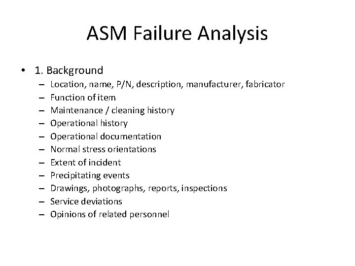
ASM Failure Analysis • 1. Background – – – Location, name, P/N, description, manufacturer, fabricator Function of item Maintenance / cleaning history Operational documentation Normal stress orientations Extent of incident Precipitating events Drawings, photographs, reports, inspections Service deviations Opinions of related personnel
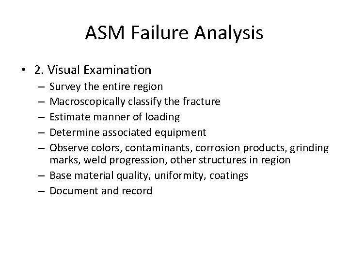
ASM Failure Analysis • 2. Visual Examination Survey the entire region Macroscopically classify the fracture Estimate manner of loading Determine associated equipment Observe colors, contaminants, corrosion products, grinding marks, weld progression, other structures in region – Base material quality, uniformity, coatings – Document and record – – –
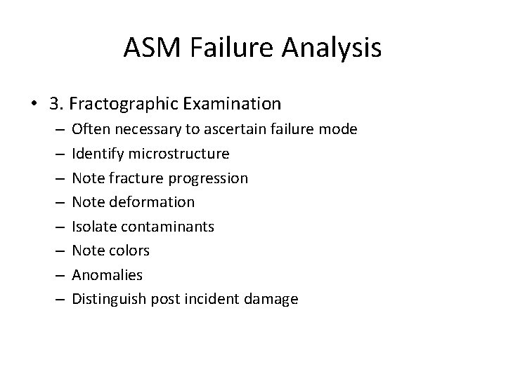
ASM Failure Analysis • 3. Fractographic Examination – – – – Often necessary to ascertain failure mode Identify microstructure Note fracture progression Note deformation Isolate contaminants Note colors Anomalies Distinguish post incident damage
ASM Failure Analysis • 4. Chemical Analysis – Base metal composition – Contaminant composition – Presence of coating on fracture surface – Corrosion product composition
ASM Failure Analysis • 5. Mechanical Properties – Bulk material properties – Anomalous material properties – Hardness – Ductility – Tensile strength – Corrosion susceptibility – SCC susceptibility
ASM Failure Analysis • 6. Macroscopic Examination – Overall homogeneity – Uniform cracking – Any differences
ASM Failure Analysis • 7. Metallographic Examination – Section polish and etch • 8. Microhardness – Traverse across crack, HAZ. Determine gradients – Inclusions, metallographic phases
ASM Failure Analysis • 9. SEM analysis – Identify microscopic fracture modes – Ductile dimpling, inter-granular, cleavage – Presence of contamination on fracture surface • 10. Microprobe – SEM-EDS of individual areas – Graphite, carbides, precipitates
ASM Failure Analysis • 11. Residual Stresses and phases – X-Ray diffraction, strain gage methods • 12. Simulation / Tests – FEA, stress analysis – Testing – Consistent with findings? • 13. Summarize findings • 14. Report and Distribute • 15. Follow-up
ASM Failure Analysis • 16. Preserve Evidence – Package carefully – DO NOT put fracture faces together – Use desiccant – Other experts, new information – Sometimes destructive testing is required
Failure Mechanisms • Parts “Fail” for many reasons (Deficiency) • Operational – Plastic deformation (permanent set, buckling) – Excessive deflection (floors, beams, shafts) – Excessive vibration (machine mounts) – Acoustics issues • Fracture – Ductile, Brittle, Fatigue, Thin Lip…
Failure Mechanisms • Corrosion – Thinning – Stress Concentrators (risers) – Corrosion Products • Wear – Thinning – Wear Products • Welding
Synergistic Effects • All failures have components of multiple failure mechanisms associated • Simultaneous presence, interacting • Task is to determine the important ones from the auxiliary modes
Some Techniques in FA • Cleaning Fracture Surfaces and SEM Observation – Clean the surface using acetone, alcohol, ultrasonic cleaner and then dry – Replicating surfaces by • Wetting the fracture surface • Wetting the adhesive side of the acetate tape • Rub the wet surface of tape to fracture surface to put impression on the tape and collecting debris • Tape is coated with gold/carbon and carried out SEM and EDAX
Some Techniques in FA • Preparation of Replicas for the TEM – Take the tape replica – Put a thin(200 A) layer of a carbon on it in a vacuum coater – Alternatively carbon can be coated on the fracture surface and then removed by the adhesive tape – Put a thin(200 A) layer of a heavy metal (Cr, Pt) to enhance contrast – Acetate tape is dissolved in a solvent (acetone) ; freeing the thin and fragile replica – Replica is removed onto a screen or grid
Some Techniques in FA • Steremicroscopy – Stereo imaging involves recording a given field of view twice at slightly different orientations and simultaneously viewing the stereo pair such that a three dimensional image is percieved – The four methods to record stereo pairs • The tilt method- where angle is applied between the two micrographs • The lateral shift method - where there is a horizontal displacement between the two micrographs • The rotation methods-where the specimen is rotated between exposure • Electromagnetic deflection of the electron beam between two images
Failure Mode & Effects Analysis (FMEA) • Defined: FMEA is a systematic tool for identifying: – effects or consequences of a potential product or process failure. – methods to eliminate or reduce the chance of a failure occurring. • Ideally, FMEA’s are conducted in the product design or process development stages [conducting an FMEA on existing products or processes may also yield benefits] • FMEA generates a living document that can be used to anticipate and prevent failures from occurring. (note: documents should be updated regularly. )
FMEA/FMECA History • The history of FMEA/FMECA goes back to the early 1950 s and 1960 s. – U. S. Navy Bureau of Aeronautics, followed by the Bureau of Naval Weapons: – National Aeronautics and Space Administration (NASA): • Department of Defense developed and revised the MIL-STD-1629 A guidelines during the 1970 s.
FMEA/FMECA History (continued) • Ford Motor Company published instruction manuals in the 1980 s and the automotive industry collectively developed standards in the 1990 s. • Engineers in a variety of industries have adopted and adapted the tool over the years.
Published Guidelines • J 1739 from the SAE for the automotive industry. • AIAG FMEA-3 from the Automotive Industry Action Group for the automotive industry. • ARP 5580 from the SAE for non-automotive applications.
FMEA is a Tool - When to Use • FMEA is most effective when it occurs before a design is released rather than “after the fact”. – focus should be on failure prevention not detection. FMEA is often a standard process used in the development of new products.
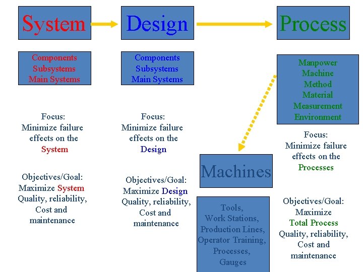
System Design Components Subsystems Main Systems Focus: Minimize failure effects on the System Objectives/Goal: Maximize System Quality, reliability, Cost and maintenance Process Manpower Machine Method Material Measurement Environment Focus: Minimize failure effects on the Design Objectives/Goal: Maximize Design Quality, reliability, Cost and maintenance Machines Tools, Work Stations, Production Lines, Operator Training, Processes, Gauges Focus: Minimize failure effects on the Processes Objectives/Goal: Maximize Total Process Quality, reliability, Cost and maintenance
What tools are available to meet our objective? • • • Benchmarking customer warranty reports design checklist or guidelines field complaints internal failure analysis internal test standards lessons learned returned material reports Expert knowledge
What are possible outcomes? • • • Actual/potential failure modes customer and legal design requirements duty cycle requirements product functions key product characteristics Product Verification and Validation
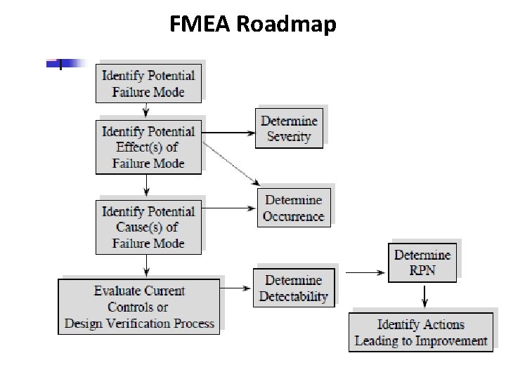
FMEA Roadmap
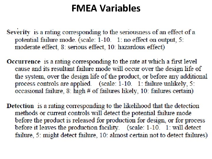
FMEA Variables
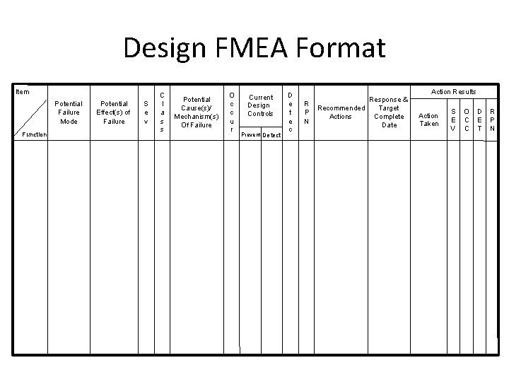
Design FMEA Format Item Potential Failure Mode Function Potential Effect(s) of Failure S e v C l a s s Potential Cause(s)/ Mechanism(s) Of Failure O c c u r Current Design Controls Prevent Detect D e t e c Action Results R P N Response & Recommended Target Actions Complete Date Action Taken S E V O C C D E T R P N
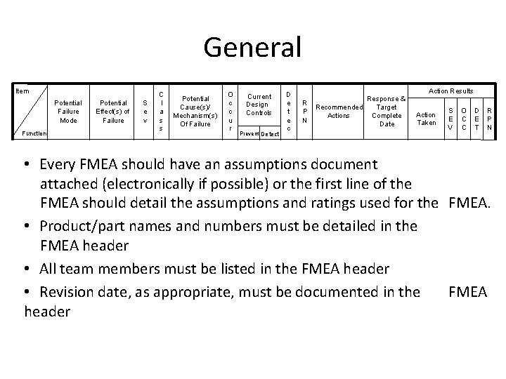
General Item Potential Failure Mode Function Potential Effect(s) of Failure S e v C l a s s Potential Cause(s)/ Mechanism(s) Of Failure O c c u r Current Design Controls Prevent Detect D e t e c Action Results R P N Response & Recommended Target Actions Complete Date Action Taken S E V O C C D E T R P N • Every FMEA should have an assumptions document attached (electronically if possible) or the first line of the FMEA should detail the assumptions and ratings used for the FMEA. • Product/part names and numbers must be detailed in the FMEA header • All team members must be listed in the FMEA header • Revision date, as appropriate, must be documented in the FMEA header
Severity • Definition: assessment of the seriousness of the effect(s) of the potential failure mode on the next component, subsystem, or customer if it occurs • Severity applies to effects • For failure modes with multiple effects, rate each effect and select the highest rating as severity for failure mode
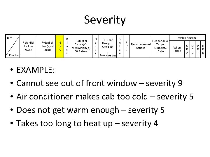
Severity Item Potential Failure Mode Function • • • Potential Effect(s) of Failure S e v C l a s s Potential Cause(s)/ Mechanism(s) Of Failure O c c u r Current Design Controls Prevent Detect D e t e c Action Results R P N Response & Recommended Target Actions Complete Date Action Taken S E V O C C EXAMPLE: Cannot see out of front window – severity 9 Air conditioner makes cab too cold – severity 5 Does not get warm enough – severity 5 Takes too long to heat up – severity 4 D E T R P N
Occurrence • Definition: likelihood that a specific cause/mechanism will occur • Be consistent when assigning occurrence • Removing or controlling the cause/mechanism though a design change is only way to reduce the occurrence rating
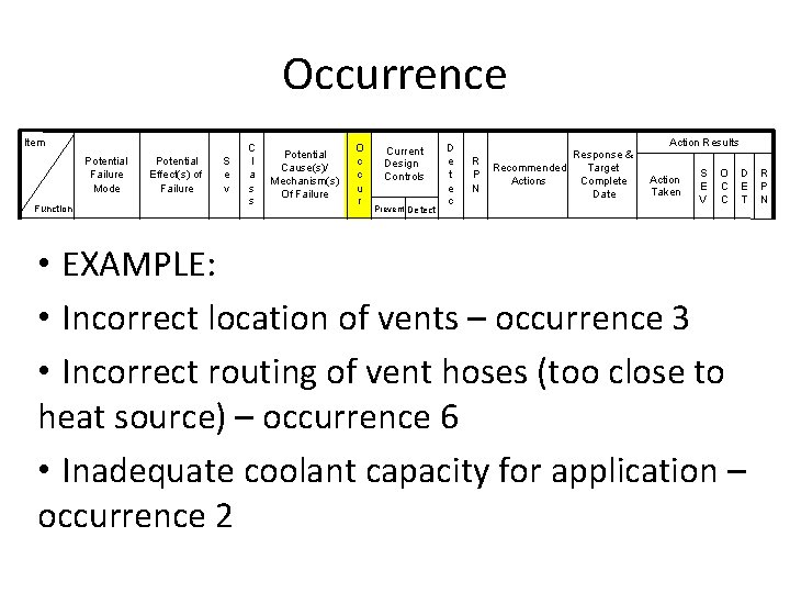
Occurrence Item Potential Failure Mode Function Potential Effect(s) of Failure S e v C l a s s Potential Cause(s)/ Mechanism(s) Of Failure O c c u r Current Design Controls Prevent Detect D e t e c Action Results R P N Response & Recommended Target Actions Complete Date Action Taken S E V O C C D E T • EXAMPLE: • Incorrect location of vents – occurrence 3 • Incorrect routing of vent hoses (too close to heat source) – occurrence 6 • Inadequate coolant capacity for application – occurrence 2 R P N
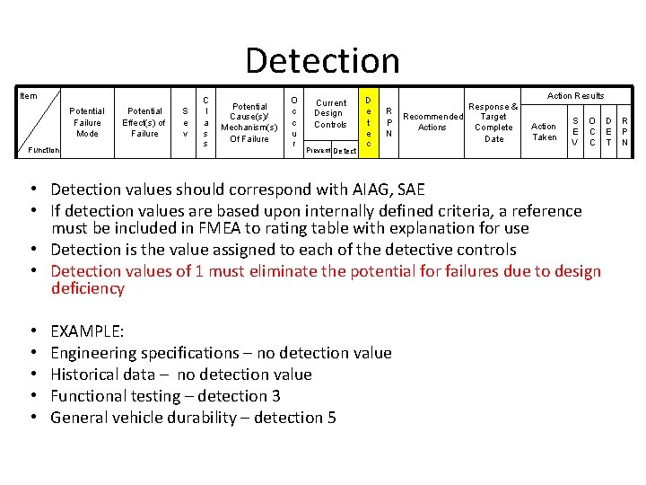
Detection Item Potential Failure Mode Function Potential Effect(s) of Failure S e v C l a s s Potential Cause(s)/ Mechanism(s) Of Failure O c c u r Current Design Controls Prevent Detect D e t e c Action Results R P N Response & Recommended Target Actions Complete Date Action Taken S E V O C C • Detection values should correspond with AIAG, SAE • If detection values are based upon internally defined criteria, a reference must be included in FMEA to rating table with explanation for use • Detection is the value assigned to each of the detective controls • Detection values of 1 must eliminate the potential for failures due to design deficiency • • • EXAMPLE: Engineering specifications – no detection value Historical data – no detection value Functional testing – detection 3 General vehicle durability – detection 5 D E T R P N
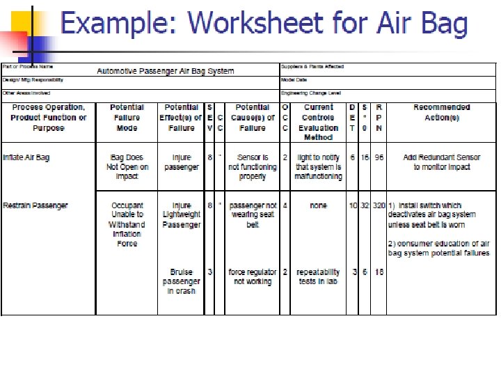
Risk Priority Number(RPN) • Severity x Occurrence x Detection • RPN is used to prioritize concerns/actions • The greater the value of the RPN the greater the concern • RPN ranges from 1 -1000 • The team must make efforts to reduce higher RPNs through corrective action • General guideline is over 100 = recommended action
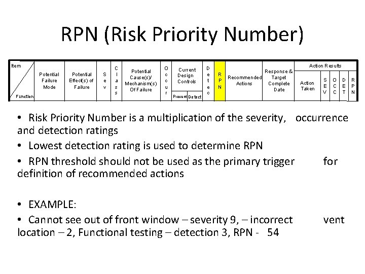
RPN (Risk Priority Number) Item Potential Failure Mode Function Potential Effect(s) of Failure S e v C l a s s Potential Cause(s)/ Mechanism(s) Of Failure O c c u r Current Design Controls Prevent Detect D e t e c Action Results R P N Response & Recommended Target Actions Complete Date Action Taken S E V O C C D E T • Risk Priority Number is a multiplication of the severity, occurrence and detection ratings • Lowest detection rating is used to determine RPN • RPN threshold should not be used as the primary trigger for definition of recommended actions • EXAMPLE: • Cannot see out of front window – severity 9, – incorrect location – 2, Functional testing – detection 3, RPN - 54 vent R P N
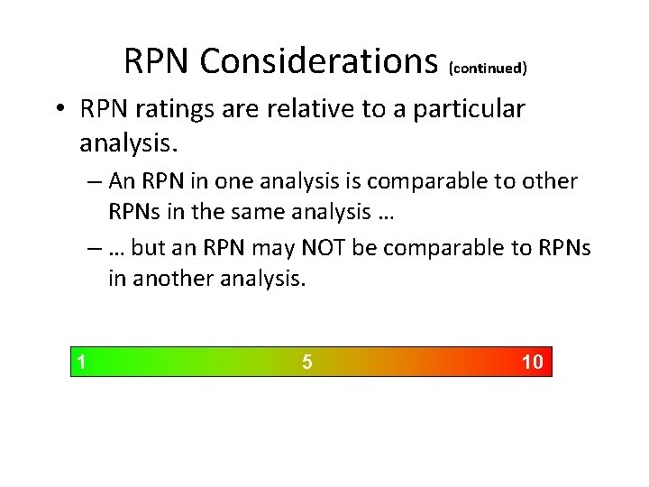
RPN Considerations (continued) • RPN ratings are relative to a particular analysis. – An RPN in one analysis is comparable to other RPNs in the same analysis … – … but an RPN may NOT be comparable to RPNs in another analysis. 1 5 10
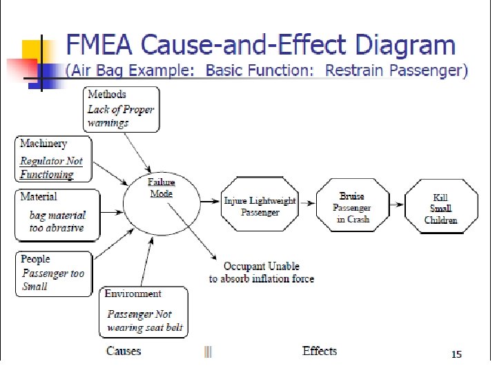
Conducting FMEA • Prior to conducting an FMEA, it is often useful to: – perform a functional analysis, and – generate FMEA cause-and-effect diagrams.
Conducting FMEA • Basic and Secondary Functions - verb~noun descriptions of what product (process) does. – Basic Function: ingress to and egress from vehicle – Secondary functions - protect occupant from noise • Failure Mode - physical description of a failure. – noise enters at door-to-roof interface • Failure Effects - impact of failure on people, equip. – driver dissatisfaction. • Failure Cause - refers to cause of the failure. – insufficient door seal.
Continuous Improvement • Last Columns of FMEA worksheet are used to identify improvement plan. – Recommend action – Identify responsibility to complete action. – Identify target dates to complete action. – List action taken and reassess RPN. • FMEA also uses a Measure - Analyze Improve - Control Cycle.
Benefits of FMEA • Contributes to improved designs for products and processes. – – Higher reliability Better quality Increased safety Enhanced customer satisfaction • Contributes to cost savings. – Decreases development time and re-design costs – Decreases warranty costs – Decreases waste, non-value added operations • Contributes to continuous improvement
Reasons FMEA’s fail Ø One person is assigned to complete the FMEA Ø Members of the FMEA team are not trained in the use of FMEA Ø Rushing through identifying the failure modes to move onto the next step of the FMEA Ø Listing the same potential effect for every failure i. e. customer dissatisfied. Ø Stopping the FMEA process when the RPN’s are calculated and not continuing with the recommended actions.
Summary • • • Remain OBJECTIVE Be aware of various failure mechanisms Design to ACTUAL loads, not estimates Analyze stress concentrations Know your material Design for brittle or ductile fracture
- Slides: 65