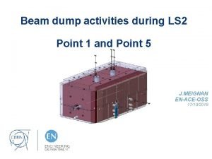
Dump Core ThermoMechanical Studies 4102017 XX Jaakko Johannes


![Boundary Conditions BEAM Thermal Contact Conductances [W/(m 2 K)] Contact Clamped HIP 2000 No Boundary Conditions BEAM Thermal Contact Conductances [W/(m 2 K)] Contact Clamped HIP 2000 No](https://slidetodoc.com/presentation_image_h/a14ffff66752b0c43fc1a56a2817f0dd/image-12.jpg)


- Slides: 42

Dump Core: Thermo-Mechanical Studies 4/10/2017 XX Jaakko Johannes Esala François-Xavier Nuiry Giulia Romagnoli Edouard Grenier Boley Jose Briz Monago Marco Calviani Vasilis Vlachoudis Tobias Polzin Yannick Coutron Didier Steyaert And all the involved people in EN-STI, EN-MME, EN-HE, TE-VSC, TE-MSC, BE-OP, BE-BI, BE-RF

Outline • Design History • Overview of thermo-mechanical simulations • Results • Steady-state • LHC 25 ns HL-LHC (Steady-state + 4 pulses) • Graphite results • Cu. Cr. Zr results • Other beam cases • Conclusions 4/10/2017 Dump Core: Thermo-Mechanical Studies 2

History • Maximum temperature in the front shaving edge Starting point: Current dump, but longer: 130 200 mm • Material: Oxygen Free Copper • Sensitivity to angle of the core Completely parallel dump impossible Angle set at 1° • Shaving process is a long (~ms) and local (~µm) process Thermal conductivity is a driving parameter 4/10/2017 200 mm BEAM Dump Core: Thermo-Mechanical Studies BEAM angle 3

Design History • m 200 m Edge rounded to spread out proton impacts and heat generation LANE P Y R T MME SY BEAM 22 % decrease • Rounded edge Location of temperature peak! 745 Other geometrical shapes and solutions also considered 15 ° mm “Sword” design: 35 % decrease in max. temperature compared to straight edge AM BE 4/10/2017 Dump Core: Thermo-Mechanical Studies 4

Material Selection MATERIAL SELECTION: • Thermal load case: Temperature increase thermal strain stress BEAM • Multi-turn, shaving impact makes thermal figure of merit difficult to assess: • Driving physical properties: ρ Density cp λ α E Specific heat Thermal conductivity Coefficient of thermal expansion Young’s Modulus Approach: 1) Material “sandwich”: 1) low density material with high temperature and thermal shock resistance 2) higher density absorbing materials 2) Good thermal conductivity 4/10/2017 Dump Core: Thermo-Mechanical Studies 5

Material Selection • Several material candidates evaluated: Graphite R 7550 Glassy Carbon Silicon Carbide Cu. Cr. Zr Copper Oxygen Free Glidcop AL-15 Copper Diamond Aluminum Ti 6 Al 4 V Molybdenum alloy TZM Tungsten alloy Inermet 180 • • • Low density Medium density High density Unacceptable temperatures and plastic deformations! Low density materials: • Graphite R 7550 • Silicon Carbide • Glassy Carbon 4/10/2017 Higher temperature in lower density materials! High elastic modulus (~400 GPa) high stresses. R 7550 better known. Low thermal conductivity ~7 W/(m K) Dump Core: Thermo-Mechanical Studies 6

Design History Medium density Low density High density HL-LHC Energy absorbed: 14. 5 k. J/pulse (16% of total) • • 10 mm of graphite not sufficient Unacceptable peak °C in Cu. Cr. Zr High steady-state temperatures Not enough space for sufficient dilution before dense materials Maximum length: 230 mm (due to vacuum tank dimensions) Cooling pipes away from particle showers 4/10/2017 Dump Core: Thermo-Mechanical Studies HL-LHC Energy absorbed: 8. 4 k. J/pulse (8. 7%) 7

ANSYS Model Overview 2 D layered shell elements: 30 layers x 5 µm = 150 µm 66 mm Slice 230 mm 40 mm s M BEA NE PLA Y R T ME SYM Rounded edge: 3 straight sections Rounded: 40 mm BEAM 120 mm 9. 5 23 24 mm Slices 10 mm 4/10/2017 23 Dump Core: Thermo-Mechanical Studies 8

Modeling Assumptions • Time stepping: 20 -60 x 150 µs (from FLUKA) • New Energy deposition map each time step • Vertical tune Q=6. 33 • Symmetry in geometry, loading and boundary conditions • Linear elastic temperature dependent material model • Dump core velocity: 0. 8 m/s • Beam impact always in the same position, in the middle 4/10/2017 Dump Core: Thermo-Mechanical Studies 9

Overview DESIGN CRITERIA: Limit Criteria Graphite Cu. Cr. Zr Method of evaluation Maximum temperature 2000 °C 300 °C ANSYS Simulations Failure criteria Mohr-Coulomb Von Mises yield ANSYS Simulations Material strength Tension: 40 MPa 1) Comp. : 130 MPa 1) 282 MPa 2) (at 22 °C) Fatigue Possible total beam dumps limitation Compare stress with S-N curves Mohr-Coulomb Safety Factor: σ1 is maximum principal stress (tensile) σ3 is minimum principal stress (compressive) ANSYS Help, Mohr-Coulomb Stress Safety Tool 4/10/2017 1) From manufacturer SGL Group, Material data sheets, and specific measurements for CERN 2) Cu. Cr. Zr Dump Core: Thermo-Mechanical Studies 3 D forged characterization at CERN (EN-MME), 2017 10

Sensitivity Studies • Sensitivity studies to validate the FEM model and assumptions: • FLUKA to ANSYS energy import, peak and total energy • Mesh convergence for graphite • Time stepping not influencing results Maximum temperature vs. dump core velocity LHC 25 ns HL-LHC beam, one pulse 1420 °C Mohr-Coulomb SF: 0. 99 • Beam impact location • Influence of dump angle and tune of the PS machine • Dump core velocity 1292 °C Mohr-Coulomb SF: 1. 21 98 °C 95 °C 4/10/2017 Dump Core: Thermo-Mechanical Studies 11
![Boundary Conditions BEAM Thermal Contact Conductances Wm 2 K Contact Clamped HIP 2000 No Boundary Conditions BEAM Thermal Contact Conductances [W/(m 2 K)] Contact Clamped HIP 2000 No](https://slidetodoc.com/presentation_image_h/a14ffff66752b0c43fc1a56a2817f0dd/image-12.jpg)
Boundary Conditions BEAM Thermal Contact Conductances [W/(m 2 K)] Contact Clamped HIP 2000 No contact Perfect thermal contact Cu. Cr. Zr - Cooling Pipe 2000 Perfect thermal contact Cooling Pipe - Water (at 26 °C) 6000 Graphite - Cu. Zr Cu. Cr. Zr Top – Cu. Cr. Zr Bottom 1) Upgrade of the PS Internal Dump in the Framework of the LHC Injectors Upgrade Project. EDMS No. 1845424 Rev. 0. 1 4/10/2017 Dump Core: Thermo-Mechanical Studies Calculated with Mikic equations: Corresponds to smooth surfaces, uniform contact pressure < 0. 05 MPa 1) Calculated with Mikic equations: Corresponds to smooth surfaces, uniform contact pressure of 0. 6 MPa 1) Analytically calculated value: 2800 W/(m 2 K) for a flow rate of 1. 5 l/min TCC = Thermal Contact Conductance HTC = Heat Transfer Coefficient 12

Steady-state, Clamped Design • Steady-state simulations are performed with averaged heating power. • The ~40 FLUKA time steps are summed and the energy is applied over the pulse period (3. 6 s for HL-LHC) • Power corresponding to a HL-LHC beam every 3. 6 seconds is used: 2400× 1010 protons/3. 6 s 667× 1010 protons/s 8323 joules/3. 6 s 2312 W Very conservative • Considered an reasonable upper limit after discussion with the operation group • TCC values and cooling performance calculated analytically are estimates. • Cooling performance shall be evaluated during prototyping and commissioning Simulations and power limits adjusted accordingly 4/10/2017 Dump Core: Thermo-Mechanical Studies 13

Steady-state, Clamped Design BEAM Graphite Max. T = 96 °C Clamped design Cu. Cr. Zr Max. T = 231 °C Thermal barrier Clamped: 96 °C HIP: 67 °C Clamped: 231 °C 29 °C 145°C HIP: 86 °C 4/10/2017 Dump Core: Thermo-Mechanical Studies 14

Steady-state, Clamped Design BEAM Baseline Temp = 96 °C Most sensitive thermal contacts: Cu. Cr. Zr - Cooling Pipe & Cooling Pipe - Water 4/10/2017 Dump Core: Thermo-Mechanical Studies Baseline Temp = 231 °C TCC = Thermal Contact Conductance HTC = Heat Transfer Coefficient 15

Steady-state, HIP Design New iteration: HIP design with precised boundary conditions Graphite – Cu. Cr. Zr TCC: 2000 1000 W/(m 2 K) 26°C Cooling Pipe - Water HTC: 6000 1000 W/(m 2 K) 48 °C Steady-state 4 pulses – HL-LHC Cu. Cr. Zr: 207 °C Graphite: 170 °C + Graphite: 1378 °C Cu. Cr. Zr: 267 °C For boundary condition calculations see: Upgrade of the PS Internal Dump in the Framework of the LHC Injectors Upgrade Project. EDMS No. 1845424 Rev. 0. 1 4/10/2017 Dump Core: Thermo-Mechanical Studies 16

Transient Thermal Results, HIP design Max. temp. in Cu. Cr. Zr Logarithmic! Initial beam impact point, Max. temp. in Graphite Beam LHC 25 ns HL-LHC Intensity 2. 4 × 10¹³ Momentum 26 Ge. V/c Size 3. 10 × 1. 45 mm×mm Pulse Steady-state + 4. pulse BEA M ~180 °C Water boiling temperature 170 °C at 8 bar Max. temperature in time 1378 °C Temperature along Z Path (at peak time) 1378 °C Graphite 210 °C 164 °C 4/10/2017 258 °C Cu. Cr. Zr Graphite Cu. Cr. Zr 258 °C Dump Core: Thermo-Mechanical Studies 17

Transient Structural Results, HIP design Exaggerated deformations! Beam LHC 25 ns HL-LHC Intensity 2. 4 × 10¹³ Momentum 26 Ge. V/c Size 3. 10 × 1. 45 mm×mm Pulse Steady-state + 4. pulse Max. strain rate ≈ 4 1/s (no elastic/plastic waves assumed) “No separation” boundary condition Deformation upward ~140 μm BEAM Unrealistic stresses due to rigid support 4/10/2017 Dump Core: Thermo-Mechanical Studies Thermal expansion Bending 18

Cu. Cr. Zr Structural Results, HIP design Cu. Cr. Zr at peak time Beam LHC 25 ns HL-LHC Intensity 2. 4 × 10¹³ Momentum 26 Ge. V/c Size 3. 10 × 1. 45 mm×mm Pulse Steady-state + 4. pulse Global maximum: 84 MPa BEA M v. Mises: 51 MPa 4/10/2017 Yield strength (300 °C) 230 MPa Representative stress 58 MPa Safety Factor 3. 96 v. Mises: 58 MPa Dump Core: Thermo-Mechanical Studies 19

Cu. Cr. Zr Conclusions and Fatigue • • Steady-state + 4 pulses Acceptable stresses in Cu. Cr. Zr Fatigue not expected to be critical for Cu. Cr. Zr Maximum temperature 258 °C (steady-state 207 °C) Max. representative von Mises stress 58 MPa Safety Factor Stress in Cu. Cr. Zr: 58 MPa (amplitude even lower) 3. 96 Maximum strain in Cu. Cr. Zr: 0. 04% 350 °C Low-cycle fatigue European Copper Institute. (2017) Cu. Cr 1 Zr Data Sheet, Retrieved from http: //www. conductivity-app. org/alloysheet/19 4/10/2017 G. Li, B. G. Thomas, J. F. Stubbins. (2000). Modeling Creep and Fatigue of Copper Alloys, Metallurgical and Materials Transactions A, pp. 2491 -2502. Vol. 31: 10 Dump Core: Thermo-Mechanical Studies 20

Cu. Cr. Zr Structural Results, HIP design Graphite at peak time X EAM -10 B Z Comp. strength 130 MPa Mohr-Coulomb SF 1. 17 6 M Pa Pa 1 M -11 150 µm 4/10/2017 40 MPa 1 mm 150 µm Stress evolution in Graphite in time Tensile strength Dump Core: Thermo-Mechanical Studies 1 mm 21

Graphite Block Studies Graphite block model: one pulse • Evaluate the effect of the slicing on graphite Beam HL-LHC • Studies with a smaller scale model with refined mesh Pulse no. One pulse Surface elements 3 D (instead of 2 D layered shells) 5 mm BEAM Initial beam impact point in the middle (highest heat generation). Slit depth: 5 mm 10 mm Fixed supports on the sides and on the bottom M BEA Thermal contact on the bottom: 2000 W/(m 2 K), ambient T=22 °C 4/10/2017 Dump Core: Thermo-Mechanical Studies 22

Graphite Block Studies Free surface = zero stress Temperature BEAM Stress due to thermal expansion (exaggerated) BEAM Y Stress Initial beam impact point 5 mm Z Stress 5 mm BEAM -90 MPa Sliced 4/10/2017 150 μm Tensile strength 40 MPa Comp. strength 130 MPa Mohr-Coulomb SF 1. 37 Dump Core: Thermo-Mechanical Studies 23

Graphite Block Studies X Path CONCLUSIONS: Z Path BEAM Y Path • Stress gradients follow temperatures gradients • Biaxial compression on the surface plane • Low stresses and temperatures outside the surface • Zero Y stress on the surface (free surface). • Low Y stresses in other parts due to thermal expansion 4/10/2017 Tensile strength 40 MPa Comp. strength 118 MPa Mohr-Coulomb SF 1. 37 Dump Core: Thermo-Mechanical Studies 24

Graphite Fatigue Preliminary analysis Determination of fatigue characteristics of NBG 18 graphite (molded) by Johan George Roberts 2007 4/10/2017 Fatigue failure and fracture mechanics of graphite for high temperature engineering testing reactor, Ishiyama et al, 1991. Dump Core: Thermo-Mechanical Studies 25

Graphite Conclusions Full model Block model (refined mesh) Steady-state + 4 pulses One Pulse 1378 °C (steady-state 170 °C) 1292 °C 1377 °C (+6. 6%) Max. stress X -106 MPa -102 MPa -94 MPa (-8%) Max. stress Z -111 MPa -107 MPa -90 MPa (-16%) 1. 17 1. 21 1. 37 (+13%) Pulses Maximum temperature Mohr-Coulomb Safety Factor CONCLUSIONS FOR GRAPHITE: • Peak temperature moderately affected by steady-state initial conditions BEAM • Stress gradients follow temperature gradients • Biaxial compression on graphite surface plane (otherwise low stresses) • Block model: Safety factor moderately improved • Graphite fatigue possibly limiting lifetime. Studies ongoing. 4/10/2017 Dump Core: Thermo-Mechanical Studies 5 mm Z Stress 26

Other Beam Scenarios • • Maximum temperature over time in Graphite Highest Int. most critical beam (with slicing safety factor >1) Highest Int. HL-LHC HL-BCMS and SFTPRO not critical HL-BCMS SFTPRO Simulations performed for the “clamped” design! With Graphite sliced block model Highest Int. : Safety Factor 1. 17 HL-LHC: Safety Factor 1. 37 4/10/2017 Dump Core: Thermo-Mechanical Studies 27

Conclusions • A dump core made of graphite and Cu. Cr. Zr is suitable for LIU beams. • 667 e 10 protons/second (2312 W) is the considered intensity rate limit for the HIP design. Further iterations of the cooling system will adjust the limit. • Cu. Cr. Zr shows reasonable safety factors with respect to HL-LHC beam. This is valid providing that the precipitation hardening following the HIP allows the recovery of thermal and mechanical properties. • Graphite fatigue seems to be a possible limitation. More actual beam dump statistics analysis are needed; Further graphite fatigue curves shall be studied. • Graphite safety factors are small, but the approach is conservative. 4/10/2017 Dump Core: Thermo-Mechanical Studies 28

Conclusions • Conservative assumptions in the simulations: • Rounded edge approximated with straight sections, leading to sharp peak temperature • Graphite compressive strength: Strength taken at room temperature. Graphite strength shows increase with temperature • Mohr-Coulomb safety factor is considered conservative for graphite • Graphite Young’s Modulus: Dynamic Young’s Modulus of 12. 8 GPa is used instead of static Young’s Modulus of 8. 5 GPa. • Tune Q=6. 33 used leads to higher temperature increase • Conservative steady-state case considered (667× 1010 protons/s) • Impact location always the same in the center 4/10/2017 Dump Core: Thermo-Mechanical Studies 29

Thank you 4/10/2017 Dump Core: Thermo-Mechanical Studies 30

Tune 4/10/2017 Dump Core: Thermo-Mechanical Studies 31

Angle 4/10/2017 Dump Core: Thermo-Mechanical Studies 32

Mesh 4/10/2017 Dump Core: Thermo-Mechanical Studies 33

Mesh details - “On the surface load case” Impact region modeled with 2 D layered shell elements coupled to 3 D elements Shell elements through-thickness thermal conduction 2 D shell elements (with layers) BEAM 3 D elements 4/10/2017 Energy from FLUKA is applied as element heat generation Temperatures TTOP 1 TE 10 2 TE 9 3 TE 8 4 TE 7 5 TE 6 6 TE 5 7 TE 4 8 TE 3 9 TE 2 10 TBOT Dump Core: Thermo-Mechanical Studies 5 µm 34

Materials • Temperature dependent material data implemented in ANSYS 4/10/2017 Dump Core: Thermo-Mechanical Studies 35

Time stepping • ANSYS HELP: Time step length should not be more than 100* • Too long time steps lead to numerically too high thermal conductivity • • • Approximate values for graphite: Lengthe = 5 e-6 m (5 micron) k = 100 W/(m K) c = 1000 J/(kg K) rho = 2000 kg/m^3 • Δt = 5 e-7 s = 0. 5 microsecond • Used time step: 1. 5 e-4 s (300 times Δt) • Smallest studied time step: 0. 5 e-4 s (100 times Δt) 4/10/2017 Dump Core: Thermo-Mechanical Studies 36

Stress waves • No elastic or plastic stress waves assumed • Smooth temperature increase during dumping • Maximum strain rate: 4 1/s Bertarelli, A. in Proceedings of the Joint International Accelerator School: Beam Loss and Accelerator Protection, Newport Beach, United States, 5– 14 November 2014, edited by R. Schmidt, CERN-2016 -002 (CERN, Geneva, 2016), pp. 159 – 227, http: //dx. doi. org/10. 5170/CERN-2016 -002. 159 J. Zazula. From Particle Cascade Simulations (FLUKA) to Finite Element Heat Transfer and Structural Deformation Analyses (ANSYS). Presented at the 2 nd Workshop on Simulating Accelerator Radiation Environment, CERN, Geneva (October 9 -11, 1995) 4/10/2017 Dump Core: Thermo-Mechanical Studies 37

4/10/2017 Dump Core: Thermo-Mechanical Studies 38

Highest Int. results • Highest Int. beam more critical than HL-LHC With Graphite Block submodel HL-LHC: 1377 °C Highest Int. : 1656 °C With Graphite Block submodel HL-LHC: 1. 37 Highest Int. : 1. 17 Intensity interlock for dumping of the Highest Int. can be specified in accordance with the functional specification 4/10/2017 Dump Core: Thermo-Mechanical Studies Simulations performed for the “clamped” design! 39

Graphite Block 4/10/2017 Dump Core: Thermo-Mechanical Studies 40

Energy import 4/10/2017 Dump Core: Thermo-Mechanical Studies 41

Irradiation damage in Cu. Cr. Zr • dpa in the order of 0. 002 dpa per year (0. 04 dpa in 20 years) (from FLUKA) • Localized peak dpa on the surface • Information for neutron irradiation found in literature. • Cu. Cr. Zr shows radiation hardening until saturation values around 0. 1 – 0. 5 dpa. [1][3] Some hardening may occur • Cu. Cr. Zr is void swelling resistant [1][2] (below 2% density change for dpa up to 150 [1]) • [3] [2] [1] Some thermal conductivity degradation may occur (5 – 10 % reduction for doses > 0. 1 dpa at < 150 °C [2]) [1] C. Bobeldijk (ed. ). (1994). Atomic and Plasma-Material Interaction Data for Fusion. Vol. 5. Supplement to the Journal Nuclear Fusion [2] S. A. Fabritsiev & S. J. Zinkle & B. N. Singh. (1996). Evaluation of copper alloys for fusion reactor divertor and first wall components. Journal of Nuclear Materials. Vol. 233 -237. pp. 127 -137. [3] M. Li & M. A. Sokolov & S. J. Zinkle. (2009). Tensile and fracture toughness properties of neutron-irradiated Cu. Cr. Zr. Journal of Nuclear Materials. Vol. 393. pp. 36 -46. 4/10/2017 Dump Core: Thermo-Mechanical Studies 42
 Jaakko husa
 Måns nilsson svinhufvud
 Prof. jaakko timonen
 Cp liitto
 Jaakko helander
 Reluktanssimoottori
 Jaakko marttinen
 Sedu intra
 Brother john
 Jaakko raunamaa
 Paradigm shift from women studies to gender studies
 Work studies core my working life answers
 Maz trucks belarus
 Acpion
 Dump cooling
 Jerry banks simulation
 Gloria dump punch recipe
 Hacking tamagotchi
 Dump heap hypothesis
 Kapasitas bucket pc 200
 Dump and clump strategy
 Sql server crash dump analysis
 Jerry spinelli movies
 Uuu dump
 Gloria dump
 Danpel
 Snarget
 Where does all the trash go in the world
 Tau2
Tau2 Loading and hauling equipment
 How to install mininet in virtualbox
 Butterworth dump
 Dump cooling
 Brain dump trigger list
 Lhc beam dump
 Ground gives way
 Midi n
 Contoh surat penawaran sewa dump truck
 Main dump
 Toxic waste dump problem voronoi
 Udp header in hexadecimal format
 Jan uythoven
 The brittle, rocky outer layer of earth
