CPC Morphing Technique Kalman filter approach to CMORPH


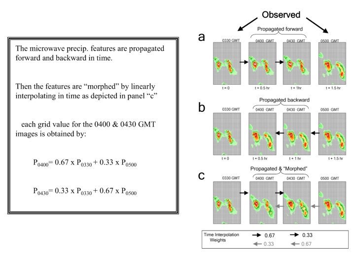


 propagated rainfall used in")


- Slides: 22
*CPC Morphing Technique Kalman filter approach to CMORPH: a skill and error assessment of instantaneous and propagated passive microwave estimated rainfall Robert Joyce RS Information Systems Pingping Xie Climate Prediction Center/NCEP/NWS John Janowiak Climate Prediction Center/NCEP/NWS Program to Evaluate High Resolution Precipitation Products (PEHRPP) workshop at the World Meteorological Organization (WMO) , Switzerland December 3 -5, 2007
Outline 1. Current CMORPH concept and methodology 2. Kalman filter approach to passive microwave rainfall 3. Comparisons of Kalman filter and current CMORPH approach 4. Conclusions and Future plans
Advection Vector Components Zonal Meridional 20 Z March 7, 2004
• Zonal NEXRAD radar rainfall spatial lag equivalent of IR cloud motion vectors (8 km/hr) increments • Meridional equivalent
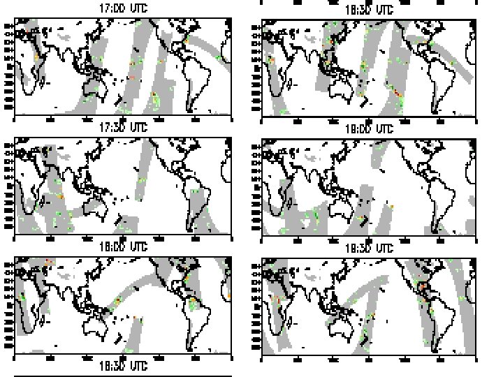
• Half hourly, 0. 25 degree lat/lon CMORPH correlation against withheld MWCOMB rainfall 23 June – 6 August 2004. Temporal distance of CMORPH to nearest PMW scan = 30 minutes (timestamp = 1, top) • temporal distance of CMORPH to nearest PMW scan = 60 minutes (timestamp = 2, top) • temporal distance of CMORPH to nearest PMW scan = 90 minutes (timestamp = 3, top) • temporal distance of CMORPH to nearest PMW scan = 120 minutes (timestamp = 4, top)
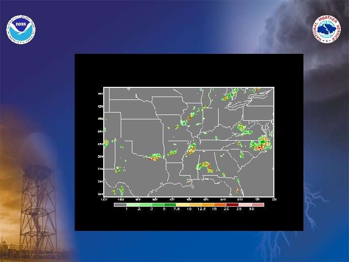
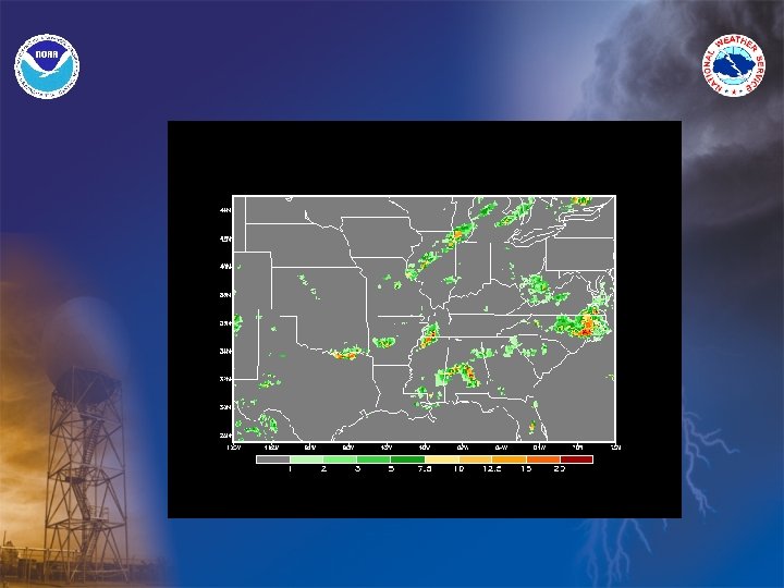
• Hourly, 0. 25 degree lat/lon CMORPH timestamp = 1 (30 minutes from nearest PMW scan) correlation with Stage II radar rainfall (top panel) • timestamp = 2 (60 minutes from nearest PMW scan) correlation with Stage II radar rainfall (2 nd from top panel) • timestamp = 3 (90 minutes from nearest PMW scan) correlation with Stage II radar rainfall (top panel) • timestamp = 4 (120 minutes from nearest PMW scan) correlation with Stage II radar rainfall (top panel)
• Correlation of 0. 25 degree lat/lon forward in time propagated passive microwave rainfall with hourly Stage II radar rainfall (top panel) • Number of non-zero rainfall pairs in correlations
• Error variance of 0. 25 degree lat/lon forward in time propagated passive microwave rainfall relative to hourly Stage II radar rainfall (top panel) • Radar rainfall colocated w/ satellite/sensor for non-zero pairs, ascending and descending nodes combined
• Normalized error variance of forward in time propagated passive microwave estimated rainfall (mm/hr) used in Climate Prediction Center (CPC) CMORPH (6 June – 30 Sept 2007). Rainfall compared against hourly, 0. 25 degree lat/lon Stage II NEXRAD radar rainfall over the U. S.
KALMAN FILTER - Kalman filter is an optimal recursive data processing algorithm, there are many ways of defining optimal dependent upon the criteria chosen to evaluate performance, here the inverse of the error variance as determined w/ radar is used. - Many practical uses incorporate discrete-time measurement samples, in this exercise we use the half hourly 8 -km forward in time propagated passive microwave rainfall. - The Kalman filter can use all information provided to it regardless of the precision, we limit this to propagations of rainfall scanned from the last ten half hourly time increments.
• Forward in time propagated NOAA-18 AMSU rainfall • Forward in time propagated TRMM TMI rainfall • Kalman filter of AMSU and TMI propagated rainfall weighted by the inverse of error variance (as determined by radar rainfall)
• Error variance of Kalman filtered 0. 25 degree lat/lon forward in time propagated passive microwave rainfall with hourly Stage II radar rainfall
• Correlation of 0. 25 deg lat/lon forward in time propagated SSMI, AMSR-E, and TMI rainfall with hourly Stage II radar rainfall. Dashed=filtered, solid lines=non-filtered (top panel) • Number of non-zero rainfall pairs in correlations (bottom panel)
• Correlation of 0. 25 deg lat/lon forward in time propagated AMSU rainfall with hourly Stage II radar rainfall. Dashed=filtered, solid lines=non-filtered (top panel) • Number of non-zero rainfall pairs in correlations (bottom panel)
• Error variance of 0. 25 degree lat/lon forward in time propagated AMSU rainfall w/ hourly Stage II radar rainfall, normalized by rainfall amount, dashed=filtered, solid lines=non-filtered (top panel) • • Variance for SSMI, AMSR-E, and TMI (bottom panel)
SUMMARY 1. TRMM TMI (and to a lesser degree ASMR-E) propagated rainfall used in CMORPH clearly exhibit more skill and less error than SSMI, and in the same manner SSMI relative to AMSU. However quite a scatter exists between satellites w/ similar sensors, thus separating ascending and descending nodes is needed to examine diurnal cycle effects 2. Satellite usage in CMORPH propagation scheme currently limited to relative location in orbit constellation (i. e. large contribution of DMSP-13) rather than skill or error characteristics. 3. The filtering process substantially reduces the error variance of the lower quality AMSU rainfall, reducing the error margin between the AMSU and high quality passive microwave sensors. 4. The filtering process increases rain coverage due to two or more passive microwave scans contributing to a point estimate in a propagation direction.
FUTURE WORK • Separate the sensor rainfall into ascending and descending nodes to determine the diurnal effects in the skill, errors, and thus the ability of the filtering process to help • Investigate the filtering effect on rainfall frequency distribution when using multiple scans to build an estimate in a single temporal direction. Determine best solution to ensure “realistic” rainfall distributions from morphing … use of instantaneous rainfall pdfs? ? ? • Complete the final morphing process by including the backward advection, again investigate the effect of additional information on skewing rainfall rate distribution. • Translate lessons learned from the NEXRAD study for use of TRMM TMI (GPM in the future) for regional depiction of skill/error variance of each sensor/algorithm.
Further Information Satellite Estimated Rainfall Validation over United States: http: //www. cpc. ncep. noaa. gov/products/janowiak/us_web. shtml Australia: http: //www. bom. gov. au/bmrc/wefor/staff/eee/Sat. Rain. Val/dailyval. html CMORPH Web: http: //www. cpc. ncep. noaa. gov/products/janowiak/cmorph. html (includes data access info. ) E-mail: john. janowiak@noaa. gov or robert. joyce@noaa. gov Paper: Joyce, R. J. , J. E. Janowiak, P. A. Arkin and P. Xie, 2004: CMORPH: A method that produces global precipitation estimates from passive microwave and infrared data at high spatial and temporal resolution. J. Hydromet. Vol. 5, No. 3, pages 487 -503. The End – Thank You