CONCEPT OF WATER HARVESTING Dr S M Talekar


 Height")


 Charcoal water filter: A simple charcoal filter")


 A recharge pit is a pit 1. 5 m")
 A soakways is a bored hole of up to 30")


 surfaces have a greater capacity of retaining rain water")


")

- Slides: 44
CONCEPT OF WATER HARVESTING Dr. S. M. Talekar Head, P. G. Dept. of Botany Mrs. K. S. K. College Beed
WATER HARVESTING DEFINITION : In scientific term, water harvesting refers to collection and storage of rain water and also other activities aimed at harvesting surface and ground water, prevention of losses through evaporation and seepage and all other hydrological studies. Rain is the 1 st form of water that we know in the hydrological cycle, hence is a primary source of water for us. Rivers, lakes and ground water are all secondary sources of water. In present time, we depend entirely on such secondary sources of water. In the process, it is forgotten that rain is the ultimate source that feeds all these secondary sources and remain ignorant of its value. Water harvesting means to understand the value of rain and to make optimum use of rain water at the place where it falls.
Fig : Where does all our water comes from?
NEED FOR WATER HARVESTING We get a lot of rain, yet we do not have water. Why? Because we have not reflected enough for the value of rain drop. The annual rainfall in India is near about 1, 170 mm. (46 inches) (as per center for Science and Environment). This is higher compare to the global average of 800 mm. (32 inches). However this rain fall occurs during short period of high intensity. Because of such intensities and short duration of heavy rain, most of rain falling on the surface to flow away rapidly leaving very little water for recharge of ground water.
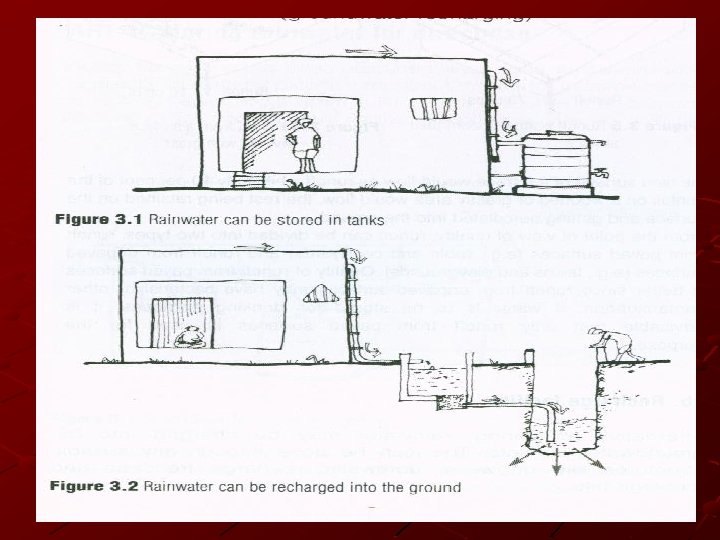
NEED FOR WATER HARVESTING India experience lack of water even for domestic uses. Cherrapunji which receives about 11000 mm. of rainfall annually. Suffers from acute storage of drinking water. This is because rain water is not conserve and allowed to drain away. This can be done by recharging it into the ground water aquifers or storing it directly.
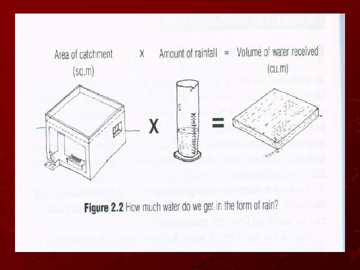
HOW MUCH WATER CAN BE HARVESTED? The total amount of water that is receives in the form of rainfall over and area is called the rain water endowment. Out of this, the amount that can be effectively harvested is called the water harvested potential. Water harvesting potential = Rainfall (mm. ) X Collection efficiency All the rain water falling over an area cannot be effectively harvested, because of evaporation, spillage.
HOW MUCH WATER CAN BE HARVESTED? A theoretical calculation that highlights the enormous potential for rain water harvesting. Consider a building with a flat terrace area of 100 sq. m. The average annual rainfall in Mumbai is approximately 2, 200 mm. Annually (87 inches) in simple terms, this means that if the terrace flow is assumed to be impermeable, and all the rain that falls on it retained without evaporation, then, in One year, there will be rain water on the terrace flow to a height of 2200 mm.
EXAMPLE Area of the plot = 100 sq. m (120 sq. yd. ) Height of rainfall = 2. 2 m (2200 mm or 87 inches) = Area of plot X Height of rainfall = 100 sq. m X 2. 2 meter = 220 cu. m (2, 20, 000 liters) Volume of rainfall Over the plot
Assuming that only 60% of the total rainfall is effectively harvested, Volume of water = 1, 32, 000 lit. harvested (2, 20, 000 lit X 0. 6) This volume is about seven times than the annual drinking water requirement of a five member family. The average daily drinking water requirement person is 10 liters.
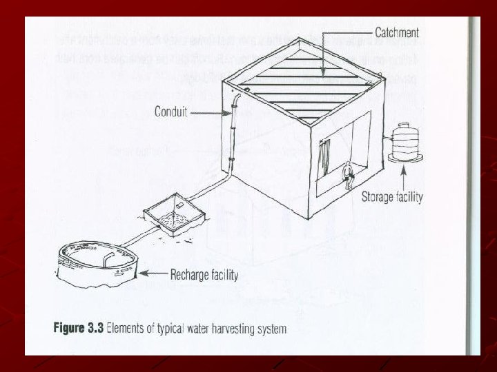
RECHARGING OF GROUND WATER AQUIFERS Various kind of recharge structures are possible which can ensure the rain water percolates in the ground instead of draining away from the surface. While some structure promote the percolation of water through soil strata at the shallow over (e. g. Recharge trenches, permeable pavements) other conducts water to greater depths from where it joints to ground water. (E. g. recharge wells) At many locations, existing features like wells, pits and tanks can be modifies to be used as recharge structures, eliminating the needs to construct any new structures. A few commonly used recharging methods are expended here. In numerable innovations and combination are these methods are possible.
DISINFECTING WATER AT HOUSEHOLD LEVEL Boiling: Boiling is one of very effective method of purification and very simple to carry out. Boiling water for 10 -20 minuets is enough to remove all biological contaminants. Chemical disinfection: Chlorination is done with stabilized bleaching powder (Calcium hypochlorite Ca. OCl 2) which is a mixture of chlorine and lime. Chlorination can kill all the types of bacteria and make water safe for drinking purposes. About 1 gm. of bleaching powder is sufficient to treat 200 lit. of water. Chlorine tablets: Chlorine tablets are easily available in market. One tablet of 0. 5 gm is enough to disinfect 20 lit. of water ( a bucket full water).
DISINFECTING WATER AT HOUSEHOLD LEVEL Filtration: a) Charcoal water filter: A simple charcoal filter can be made in drum or an earthen pot. The filter is made of gravel, sand charcoal, all of which is easily available. b) Sand filter: Sand filters have commonly available sand as a filter media, sand filter are easy and cheap to construct these filters can be used for treatment of water to effectively remove turbidity (suspended particle like silt and clay), colour and microorganisms from the water. C) Ceramic filters: These filters are manufacture commercially on a wide scale. Most of the water purifier’s available in the market or of this tank.
Fig. : Simple sand filter can be constructed at a domestic level
RECHARGE OF GROUND WATER CAN BE DONE BY FOLLOWING TYPES: 1. Bore wells/ Dug wells 2. Recharge pits( Recharge wells) 3. Soakaways (percolation pits) 4. Recharge trenches 5. Permeable surfaces
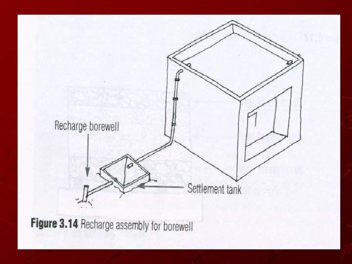
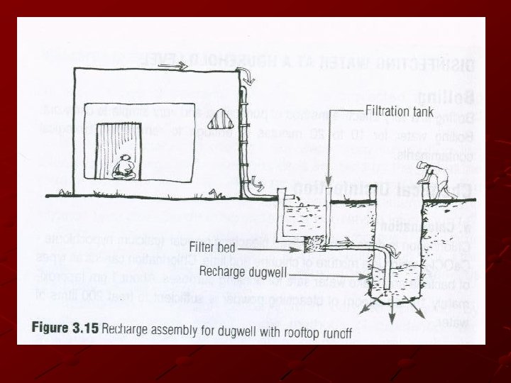
1. BORE WELLS/ DUG WELLS… Recharging of ground water for bore wells and dug wells can be done directly with rooftop runoff. Rain water i. e. collected on the roof top of the building is diverted by drain pipes to a settlement or filtration tank, from which it flows into recharge well (Bore well/ Dug well). If bore well is used for recharging, then the casing (outer pipe) of a bore well should be preferably be a slotted or perforated pipe so that more surface area is available for the water to percolate. Developing a bore well would increase its recharging capacity (Developing is a process where water or air is forced into the well under pressure to loosen the soil strata surrounding the bore to make it more permeable).
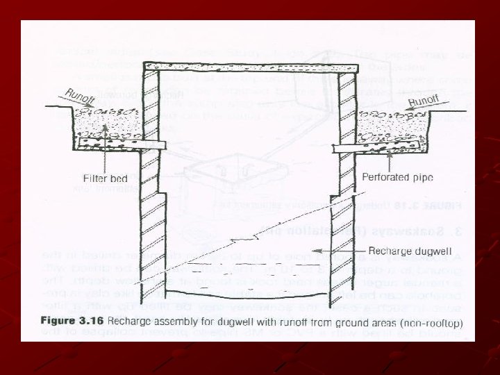
. . . 2. BORE WELLS/ DUG WELLS. . If a dug well is used for recharge the well lining should have opening (Weep-holes) at a regular intervals to allow seepage of water though the sites. Dug well should be covered prevent mosquito breeding and entry of leaves and debris. The bottom of recharge dug well should be desilted annually to maintain the intake capacity. It is preferred that dug wells/ bore wells used for recharging should be shallower than the water table. Ensure that recharge of well should be sufficient thickness of soil medium though which it has to pass before it joins the ground water.
… 1. BORE WELLS/ DUG WELLS. . Any old well which has become this function can be used for recharging, since the depth of such well is above the water level. Precautions are to be taken of physical matter in the runoff water like silt and floating debris should not enter into the well. It may cause clogging a recharging structure. It is preferred that dug wells/ bore wells used for recharging should be shallower than the water table.
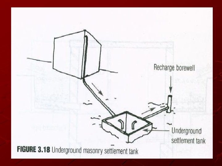
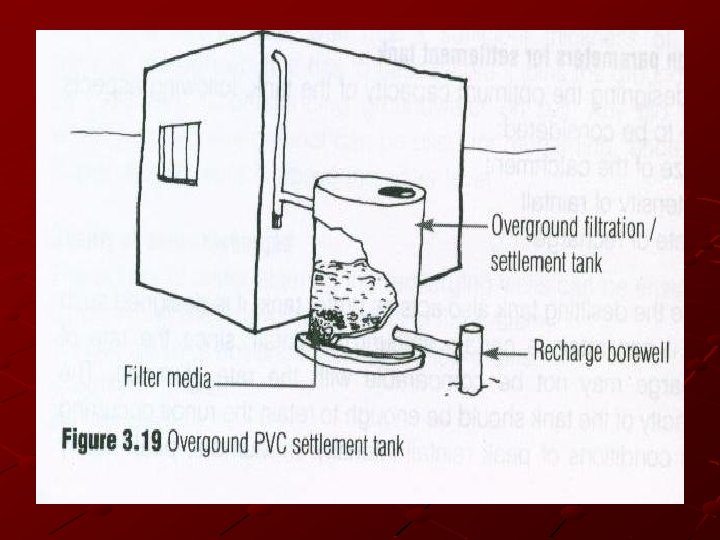
QUALITY OF WATER RECHARGED The quality of water entering the recharging wells can be ensured by providing the following elements in the system: 1. Filter mesh at entrance point of rooftop drains 2. Settlement chamber 3. Filter bed
DESIGN PARAMETERS OF SETTLEMENT TANK For designing the optimum capacity of the tank, following aspects have to be considered § Size of the catchments § Intensity of rainfall § Rate of recharge
DESIGN PARAMETERS OF SETTLEMENT TANK Since the desilting time also acts as a buffer time, it is design in such a way that it can retain the certain amount of rainfall, since the rate of recharge may not be comparable with the rate of runoff. The capacity of the tank should be enough to retain runoff occurring from conditions of peak rainfall intensity. E. g. In Mumbai, peak hourly rainfall is 90 mm. ( Based on 25 years frequency). The rate of recharge in comparison to runoff is a critically factor however accurate recharge rate is not available without delayed geo hydrological studies.
DESIGN PARAMETERS OF SETTLEMENT TANK The capacity of recharge time is design to retain runoff from at list 15 rainfall of peak intensity (22. 5 mm/hr. , save 25 mm. ) Suppose the following data is available, Area of roof top catchments area (A) = 100 sq. m. Peak rainfall in 15 min. (r) = 25 mm (0. 025 m) Runoff coefficient (C) = 0. 85 Then, capacity of desilting tank =Axrx. C = 100 x 0. 025 x 0. 85 = 20125 cu. m (2, 125 liters)
2. RECHARGE PITS (RECHARGE WELL) A recharge pit is a pit 1. 5 m to 3 m wide and 2 m to 3 m deep. The excavated pit is lined with a brick/stone wall with openings (weep-holes) at regular intervals. The area of the pit can be covered with a perforated cover. The method for designing a recharge pit is similar to that for a settlement tank.
3. SOAKWAYS (PERCOLATION PIT) A soakways is a bored hole of up to 30 cm diameter drilled with a manual auger unless hard rock is found at a shallow depth. The borehole can be left unlined if a stable soil formation like clay is present. In such a case, the soakways may be filled up with a filter media like brickbats. In unstable formations like sand, the soakways should be lined with PVC or MS pipe to prevent collapse of the vertical sides. The pipe may be slotted/perforated to promote percolation through the sides. A small sump is built at the top end of the soakway where some amount of runoff can be retained before it infiltrates through the soakway. Since the sump also acts like a buffer in the system, it has to be designed on the basis of expected runoff as described for settlement tanks.
Fig. : Details of Soakways
4. RECHARGE TRENCHES Recharging through recharge trenches, recharge pits and soakways is simpler compared to recharge through wells. Fewer precautions have to be taken to maintain the quality of rainfall runoff. For this type of structure, i. e. no restriction on the type catchments from which water is to be harvested i. e. both covered and uncovered catchments can be taped. A recharge trench is simply a continuous trench excavated in the ground and refilled in the porous media like pebbles, boulders or brick bats. Recharge trench can be 0. 5 m to 1 m wide and 1 m to 1. 5 m deep. The length of recharge trench is decided as per the amount of runoff. The recharge trench should be periodically clean. 1. 5 m. is less permeable. To enhance the recharge rate the percolation pit can be provided at the bottom of the trench.
DESIGN OF RECHARGE TRENCH Methodology of design of recharge trench is similar to the design of settlement tank the difference is that the water holding capacity of recharge trench is less than its gross volume because it is filled with porous material. A factor of loose density (Voids ratio) of the medium as to be applied to the equation. Using the same method as used for design of settlement tank. Area of rooftop catchment (A) = 100 sq. m. Peak rainfall in 16 min. (r) = 25 mm. (0. 025 m. ) Runoff coefficient (C) = 0. 85 Voids ratio (D) = 0. 5 (Assumed)
DESIGN OF RECHARGE TRENCH Required capacity of recharge tank = (A x r x C) D = (100 x 0. 025 x 0. 85) 0. 5 = 4. 25 cu. m (4, 250 lit. ) The voids ratio of the filler material varies with the kind of material used like bricks beds, pebbles and gravels, voids ratio of 0. 5 may be assume. The designing of recharge trench can be calculated by considering a fixed depth and width.
Fig. : Design of Recharge trench
5. PERMEABLE SURFACES Unpaved (uncovered) surfaces have a greater capacity of retaining rain water on surface. Patch of grass would retain a large proportion of the rain water falling on it, yielding only 10 -15 % as runoff. The maximum amount of water can be retained on such surface will naturally percolate in the ground. This type of surfaces contributes the natural recharge of ground water. If the harvested water is used direct uses or for recharging the ground water, it is most important to assure that the rain water is collected is filled from any pollutant that might be added to the rain water form the atmosphere or the catchments. while polluted water directly used for consumption would have a immediate impact on health, polluted water recharge into the ground would cause long-term problem of aquifer pollution. Damage done to aquifers by recharging by polluted water is permanent damage. Some of the precaution measures have been summarized.
PERMEABLE SURFACES At the catchments level Ø Keeping the catchments clay Ø Using grating to trap debris at the catchments itself Ø Paving the catchments with ceramic tiles, stone tiles or other such non erosive materials. At the channel (conduit) level Ø Provision of first-flush to drain runoff from initial spell of rain Before recharging Ø Allowing for sedimentation of the water Ø Filtering the water
Fig. : Permeable Pavements
Note: For industries, it is very necessary to ensure that the catchments surfaces must free from chemical waste, fuels, lubricants etc. some physical biological and chemical treatment is given for these waters, and it is difficult to remove chemical impurities. E. g. : Water hyacinths ( Echornia, Lotus, Hydrila, etc. )
COST OF WATER HARVESTING Typically, installing a water harvesting system in a building would cost between Rs. 2, 000 to 30, 000 for buildings of about 300 sq. m. It is difficulty to make an exact estimate of cost because it varies widely depending on the availability of existing structure like wells and tanks which can be modified to be used for water harvesting. The cost estimated mentioned about is for an existing building. The cost is to comparatively less. If the system were incorporated during the construction of building itself. Some basic rates of construction activities and materials have been given here, which may be helpful in calculating the total cost of structure.
APPROXIMATELY COSTS OF COMMON ITEMS OR WORK IN WATER HARVESTING Item Unit Rate (Rs. ) Excavation in soils cu. m. 90 Excavation in rocks cu. m. 150 Brickwork with cement mortar (1: 6) cu. m. 1400 Plain cement concrete (1: 3: 6) cu. m. 1500 Reinforced cement concrete (1: 2: 4) Including steel bars, shuttering etc. cu. m. 4700 - 110 mm diameter - 200 mm diameter 165 275 Making boreholes in soft soil ( with 150 mm diameter PVC casting) meter 180 PVC piping for rainwater pipes
Model scheme of water harvesting (Tata Institute of Social Sciences)
The range of water harvesting methods presented here is by no means complete, there being no limits to innovation in techniques that can be applied. This is just beginning. THANK YOU save water… save life… save earth…