CNC PROGRAMMING By JOBIN JOY Cutter diameter compensation

CNC PROGRAMMING By, JOBIN JOY

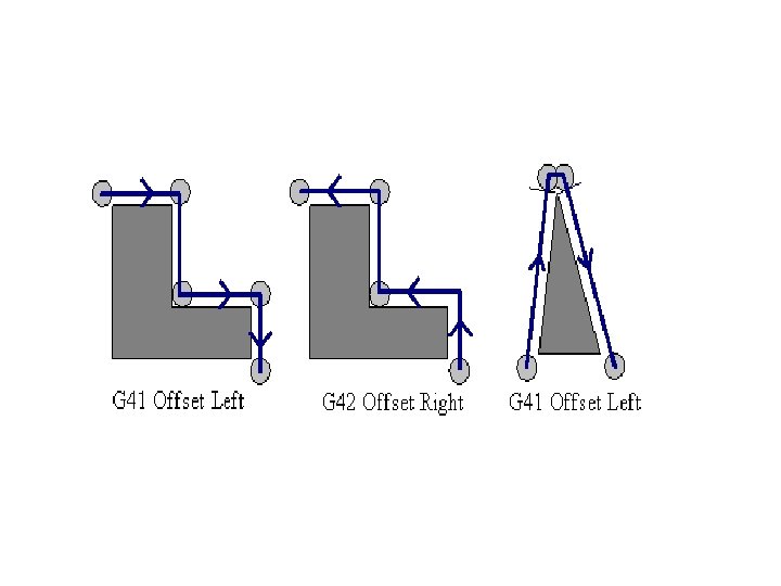
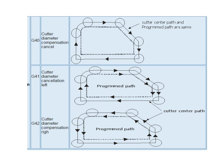
Cutter diameter compensation • When milling a contour, the tool radius center is used as the reference point on the tool while writing the program, but the part is actually cut by the point on the cutter periphery. This point is at 'r' distance from the tool center. This means that the programmer should shift the tool center away from the part in order to perform the cutting by the tool cutting edge. The shift amount depends upon the part geometry and tool radius. This technique is known as tool radius compensation or cutter radius compensation.

• G 40 -CANCEL • G 41 -CUTTER COMPENSATION LEFT • G 42 -CUTTER COMPENSATION RIGHT

Programmingmodes Programming mode should be specified when it needs to be changed from absolute to incremental and vice versa. There are two programming modes, absolute and incremental and is discussed below.
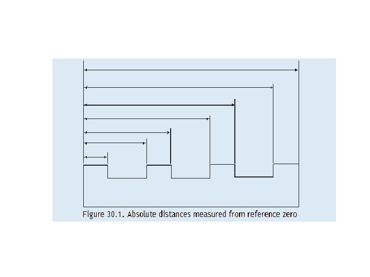
 In absolute programming, all measurements are made from")
• Absolute programming (G 90) In absolute programming, all measurements are made from the part origin established by the programmer and set up by the operator. Any programmed coordinate has the absolute value in respect to the absolute coordinate system zero point. The machine control uses the part origin as the reference point in order to position the tool during program execution.
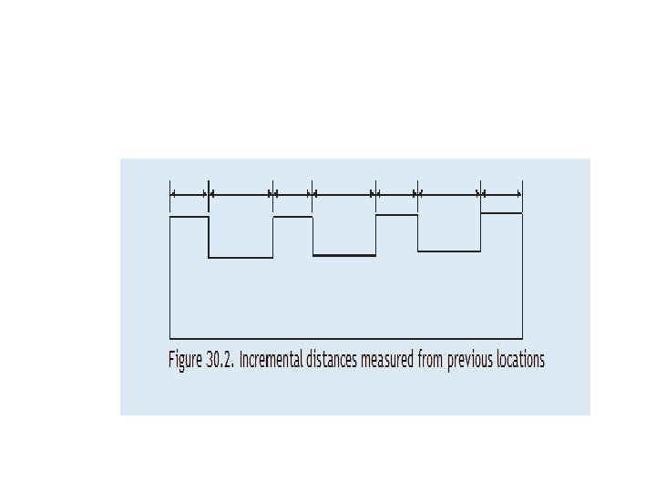
 • In incremental programming, the tool movement is measured")
Relative programming (G 91) • In incremental programming, the tool movement is measured from the last tool position. The programmed movement is based on the change in position between two successive points. The coordinate value is always incremented according to the preceding tool location. The programmer enters the relative distance between current location and the next point
 The unconditional jump is used to")
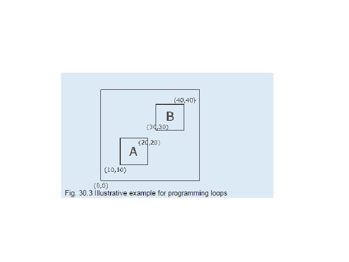
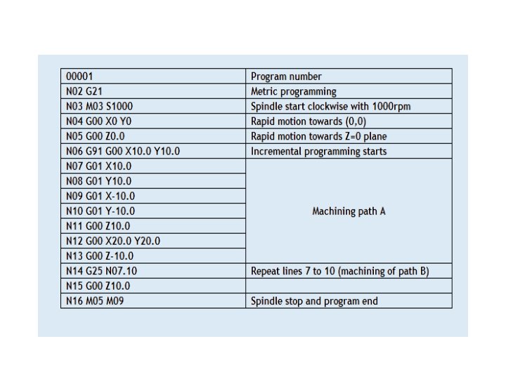
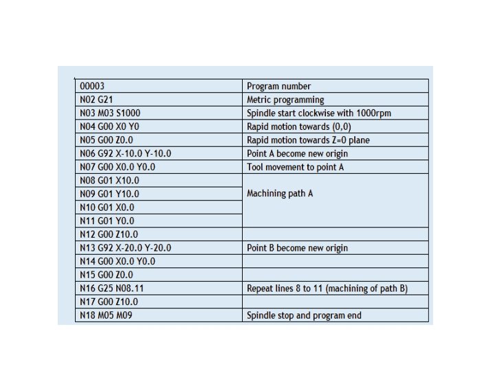
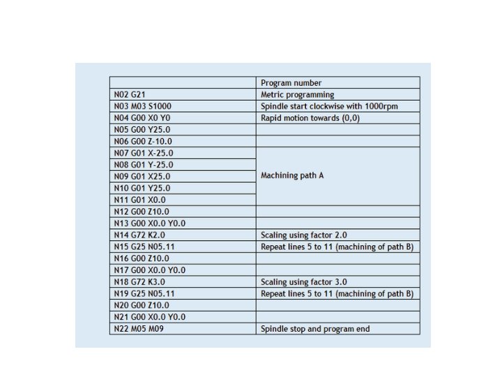
• Loops and Unconditional jump (G 25) The unconditional jump is used to repeat a set of statements a number of times.

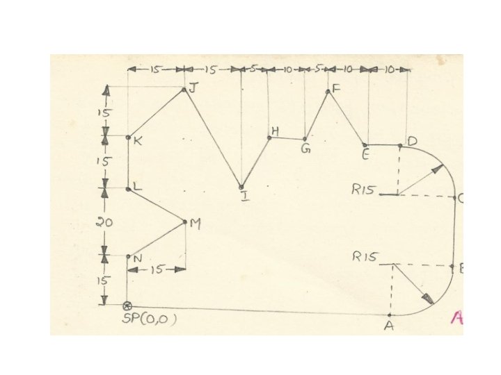
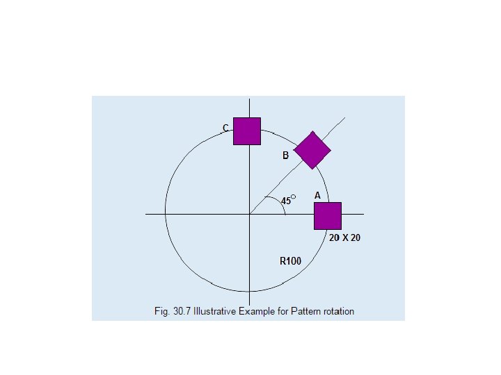
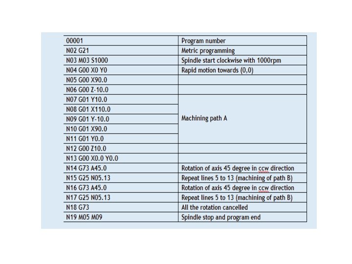
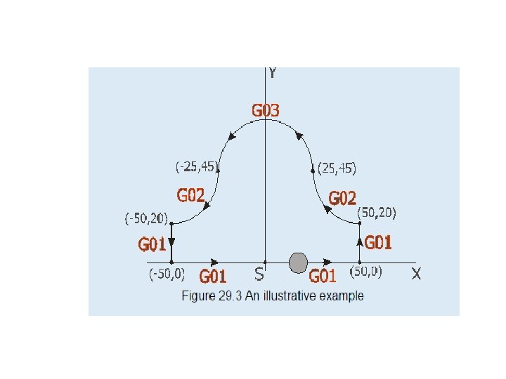
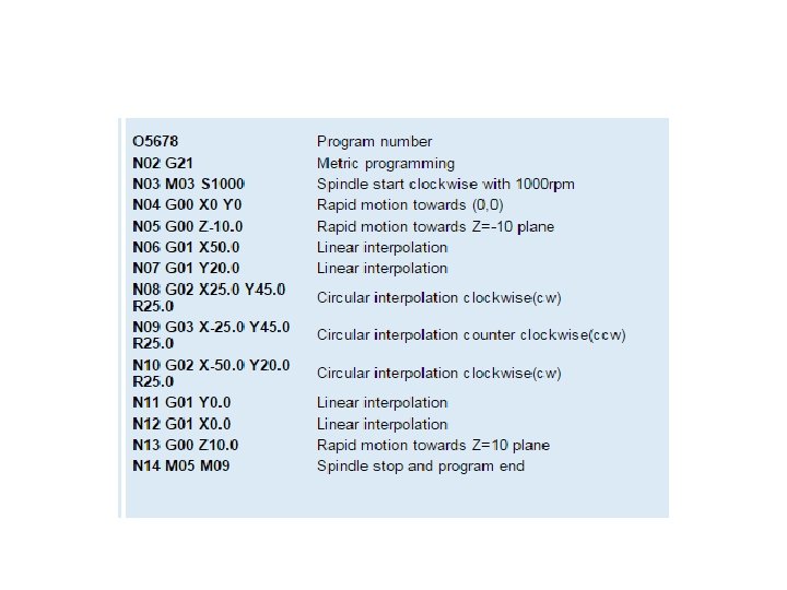
In the above example, the program statements from N 70 to N 100 are repeated once when the statement N 160 is executed. Usually the G 25 is used after a mirror statement. Illustrative example geometry and its program are given below

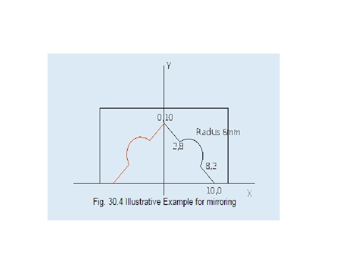
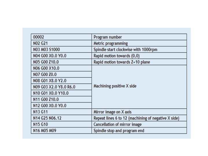
• Mirroring • The mirroring command is used when features of components shares symmetry about one or more axes and are also dimensionally identical. By using this code components can be machined using a single set of data and length of programs can be reduced.

• G 10 cancellation of mirroring image G 11 Mirror image on X axis G 12 Mirror image on Y axis G 13 Mirror image on Z axis

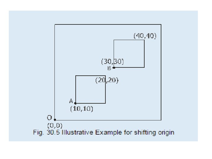
• Shifting origin G 92 code is used to temporarily shift the origin to the reference point specified.

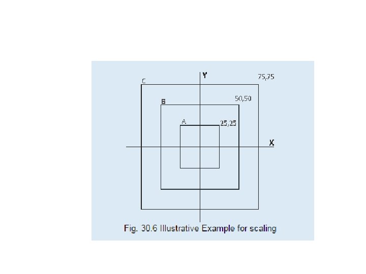
• Scaling function is used to program geometrically similar components with varying sizes. Syntax: G 72 Kk, where k is the scaling factor. The scaling command can be cancelled by using the statement G 72 K 1. 0.

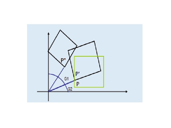
• Pattern rotation is used to obtain a pattern of similar features. G 73 code is used to rotate the feature to form a pattern. Syntax G 73 Aa, where 'a' is the angle of rotation. This command is cumulative, and the angle gets added up on time the program is executed. So all the rotational angle parameters should be cancelled using the code G 73.
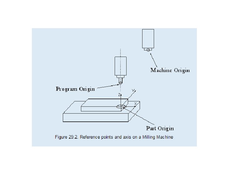
 Machine Origin The machine origin is a fixed")
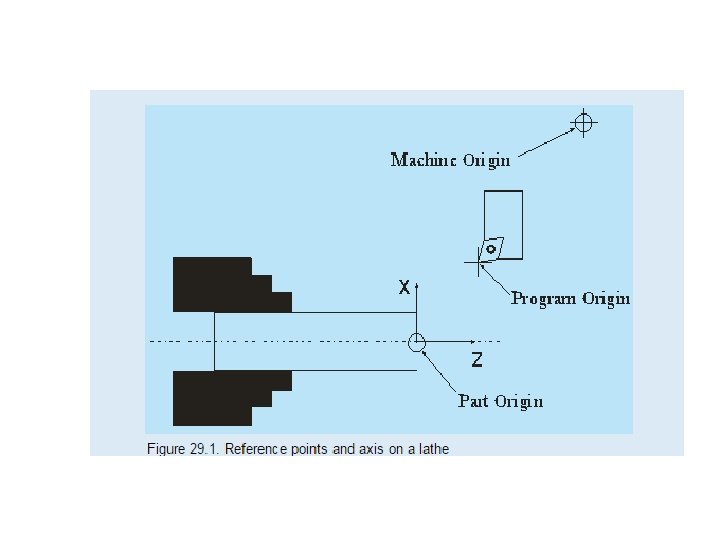
• Reference Points • a) Machine Origin The machine origin is a fixed point set by the machine tool builder. Usually it cannot be changed. Any tool movement is measured from this point. The controller always remembers tool distance from the machine origin.

• Program Origin It is also called home position of the tool. Program origin is point from where the tool starts for its motion while executing a program and returns back at the end of the cycle. This can be any point within the workspace of the tool which is sufficiently away from the part. In case of CNC lathe it is a point where tool change is carried out.

• Part Origin The part origin can be set at any point inside the machine's electronic grid system. Establishing the part origin is also known as zero shift, work shift, floating zero or datum. Usually part origin needs to be defined for each new setup. Zero shifting allows the relocation of the part. Sometimes the part accuracy is affected by the location of the part origin. Figure 29. 1 and 29. 2 shows the reference points on a lathe and milling machine

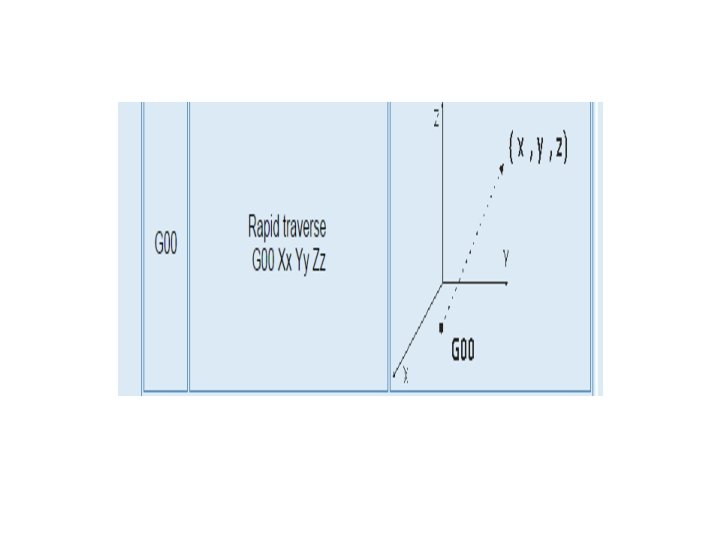
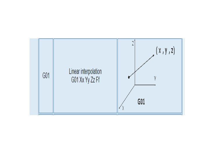
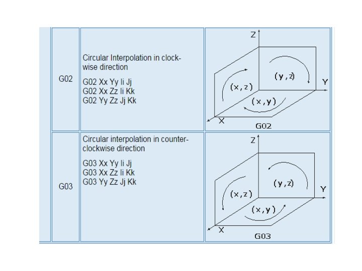
• CNC Code Syntax

• Types of CNC codes • Preparatorycodes The term "preparatory" in NC means that it "prepares" the control system to be ready for implementing the information that follows in the next block of instructions. A preparatory function is designated in a program by the word address G followed by two digits. Preparatory functions are also called G-codes and they specify the control mode of the operation

• Miscellaneous codes Miscellaneous functions use the address letter M followed by two digits. They perform a group of instructions such as coolant on/off, spindle on/off, tool change, program stop, or program end. They are often referred to as machine functions or M-functions. Some of the M codes are given below.

• M 00 Unconditional stop M 02 End of program M 03 Spindle clockwise M 04 Spindle counterclockwise M 05 Spindle stop M 06 Tool change (see Note below) M 30 End of program

• In principle, all codes are either modal or nonmodal. Modal code stays in effect until cancelled by another code in the same group. The control remembers modal codes. This gives the programmer an opportunity to save programming time. .

• Non-modal code stays in effect only for the block in which it is programmed. Afterwards, its function is turned off automatically.

• For instance G 04 is a non-modal code to program a dwell. After one second, which is say, the programmed dwell time in one particular case, this function is cancelled. To perform dwell in the next blocks, this code has to be reprogrammed. The control does not memorize the non-modal code, so it is called as one shot codes. One-shot commands are non-modal. Commands known as "canned cycles" (a controller's internal set of preprogrammed subroutines for generating commonly machined features such as internal pockets and drilled holes) are non-modal and only function during the call

- Slides: 51