Circuit Analysis Circuit Analysis using SeriesParallel Equivalents 1


 – the voltage present at the output terminals")
 – the resistance measured across the output terminals")


. Source transformation")
. v As i =")


 – the current through the shorted load terminals")

 – the resistance measured across the open load")


- Slides: 71
Circuit Analysis
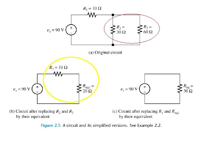
Circuit Analysis using Series/Parallel Equivalents 1. Begin by locating a combination of resistances that are in series or parallel. Often the place to start is farthest from the source. 2. Redraw the circuit with the equivalent resistance for the combination found in step 1. 3. Repeat steps 1 and 2 until the circuit is reduced as far as possible. Often (but not always) we end up with a single source and a single resistance. 4. Solve for the currents and voltages in the final equivalent circuit.
Working Backward
Find current flowing each resistor
Voltage Division
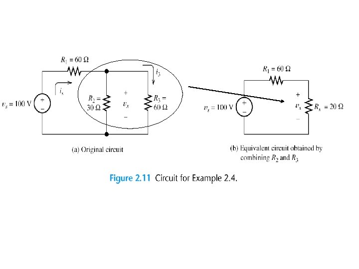
Application of the Voltage. Division Principle
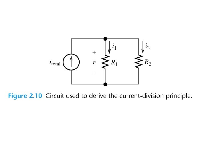
Current Division
Application of the Current-Division Principle
• Voltage division and • current division
Current division
Although they are very important concepts, series/parallel equivalents and the current/voltage division principles are not sufficient to solve all circuits.
Mesh Current Analysis Sources
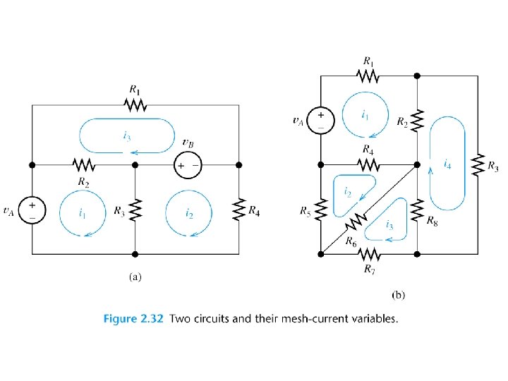
Definition of a loop Definition of a mesh
Choosing the Mesh Currents When several mesh currents flow through one element, we consider the current in that element to be the algebraic sum of the mesh currents.
Writing Equations to Solve for Mesh Currents If a network contains only resistors and independent voltage sources, we can write the required equations by following each current around its mesh and applying KVL.
For mesh 1, we have For mesh 2, we obtain For mesh 3, we have
Determine the two mesh currents, i 1 and i 2, in the circuit below. For the left-hand mesh, -42 + 6 i 1 + 3 ( i 1 - i 2 ) = 0 For the right-hand mesh, 3 ( i 2 - i 1 ) + 4 i 2 - 10 = 0 Solving, we find that i 1 = 6 A and i 2 = 4 A. (The current flowing downward through the 3 -W resistor is therefore i 1 - i 2 = 2 A. )
Mesh Currents in Circuits Containing Current Sources *A common mistake is to assume the voltages across current sources are zero. Therefore, loop equation cannot be set up at mesh one due to the voltage across the current source is unknown Anyway, the problem is still solvable.
As the current source common to two mesh, combine meshes 1 and 2 into a supermesh. In other words, we write a KVL equation around the periphery of meshes 1 and 2 combined. It is the supermesh. Mesh 3: Three linear equations and three unknown
Find the three mesh currents in the circuit below. Creating a “supermesh” from meshes 1 and 3: -7 + 1 ( i 1 - i 2 ) + 3 ( i 3 - i 2 ) + 1 i 3 = 0 [1] Around mesh 2: 1 ( i 2 - i 1 ) + 2 i 2 + 3 ( i 2 - i 3 ) = 0 [2] Finally, we relate the currents in meshes 1 and 3: i 1 - i 3 = 7 [3] Rearranging, i 1 - 4 i 2 + 4 i 3 = 7 [1] -i 1 + 6 i 2 - 3 i 3 = 0 [2] i 1 [3] - i 3 = 7 Solving, i 1 = 9 A, i 2 = 2. 5 A, and i 3 = 2 A.
supermesh of mesh 1 and mesh 2 branch current source
Three equations and three unknown.
Mesh-Current Analysis 1. If necessary, redraw the network without crossing conductors or elements. Then define the mesh currents flowing around each of the open areas defined by the network. For consistency, we usually select a clockwise direction for each of the mesh currents, but this is not a requirement. 2. Write network equations, stopping after the number of equations is equal to the number of mesh currents. First, use KVL to write voltage equations for meshes that do not contain current sources. Next, if any current sources are present, write expressions for their currents in terms of the mesh currents. Finally, if a current source is common to two meshes, write a KVL equation for the supermesh. 3. If the circuit contains dependent sources, find expressions for the controlling variables in terms of the mesh currents. Substitute into the network equations, and obtain equations having only the mesh currents as unknowns. 4. Put the equations into standard form. Solve for the mesh currents by use of determinants or other means. 5. Use the values found for the mesh currents to calculate any other currents or voltages of interest.
Superposition • Superposition Theorem – the response of a circuit to more than one source can be determined by analyzing the circuit’s response to each source (alone) and then combining the results Insert Figure 7. 2
Superposition Insert Figure 7. 3
Superposition • Analyze Separately, then Combine Results
Use superposition to find the current ix. Current source is zero – open circuit as I = 0 and solve i. Xv Voltage source is zero – short circuit as V= 0 and solve i. Xv
Use superposition to find the current ix. The controlled voltage source is included in all cases as it is controlled by the current ix.
Voltage and Current Sources Insert Figure 7. 7
Voltage and Current Sources Insert Figure 7. 8
Voltage and Current Sources Insert Figure 7. 9
Source Transformation Under what condition, the voltage and current of the load is the same when operating at the two practical sources? For voltage source For current source , We have,
Voltage and Current Sources • Equivalent Voltage and Current Sources – for every voltage source, there exists an equivalent current source, and vice versa
Thevenin’s Theorem • Thevenin’s Theorem – any resistive circuit or network, no matter how complex, can be represented as a voltage source in series with a source resistance
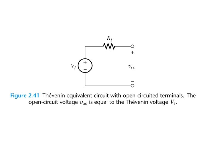
Thevenin’s Theorem • Thevenin Voltage (VTH) – the voltage present at the output terminals of the circuit when the load is removed Insert Figure 7. 18
Thevenin’s Theorem • Thevenin Resistance (RTH) – the resistance measured across the output terminals with the load removed
Thévenin Equivalent Circuits
Thévenin Equivalent Circuits
Thévenin Equivalent Circuits
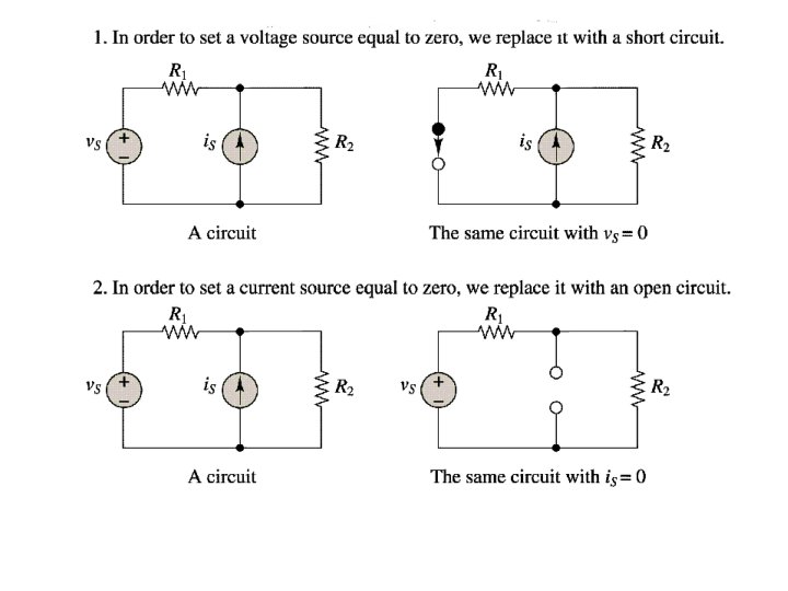
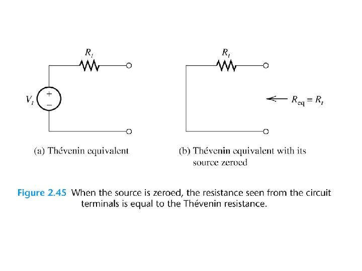
Finding the Thévenin Resistance Directly When zeroing a voltage source, it becomes a short circuit. When zeroing a current source, it becomes an open circuit. We can find the Thévenin resistance by zeroing the sources in the original network and then computing the resistance between the terminals.
Computation of Thévenin resistance
Equivalence of open-circuit and Thévenin voltage
A circuit and its Thévenin equivalent
Superposition As the voltage source does not contribute any output voltage, Only the current source has the effect.
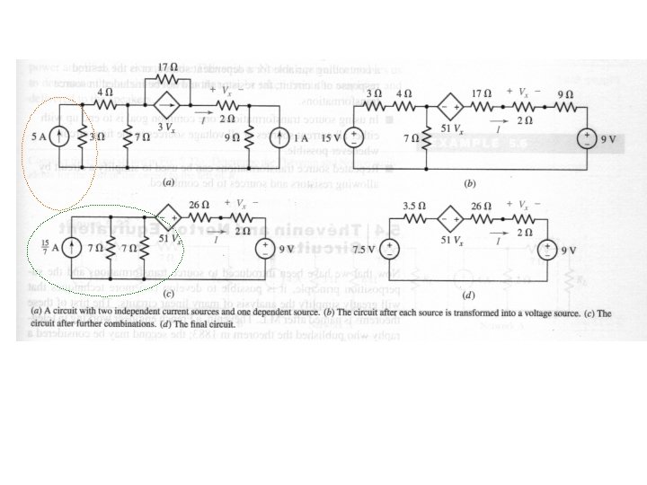
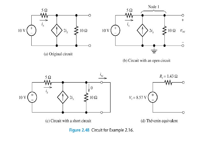
Determine the Thévenin and Norton Equivalents of Network A in (a). Source transformation
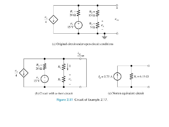
Find the Thévenin equivalent of the circuit shown in (a). v As i = -1, therefore, the controlled voltage source is -1. 5 V. Use nodal analysis at node v, Thus, Rth =v/I = 0. 6/1 = 0. 6 ohms
Applications of Thevenin’s Theorem • Load Voltage Ranges – Thevenin’s theorem is most commonly used to predict the change in load voltage that will result from a change in load resistance
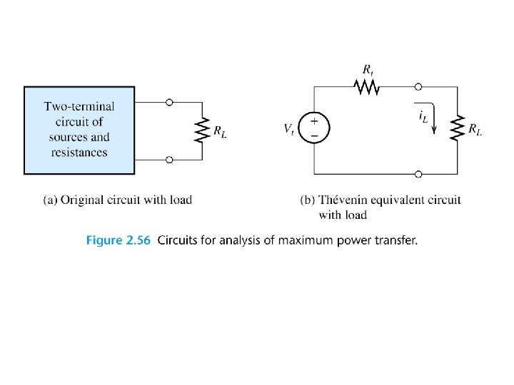
Applications of Thevenin’s Theorem • Maximum Power Transfer – Maximum power transfer from a circuit to a variable load occurs when the load resistance equals the source resistance – For a series-parallel circuit, maximum power occurs when RL = RTH
Applications of Thevenin’s Theorem • Multiload Circuits Insert Figure 7. 30
Norton’s Theorem • Norton’s Theorem – any resistive circuit or network, no matter how complex, can be represented as a current source in parallel with a source resistance
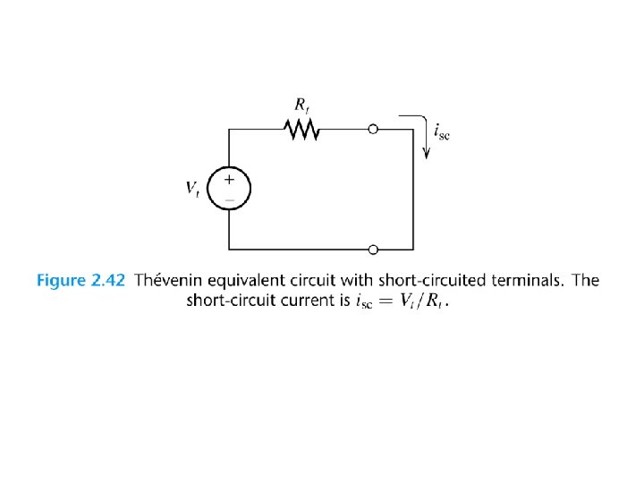
Norton’s Theorem • Norton Current (IN) – the current through the shorted load terminals Insert Figure 7. 35
Computation of Norton current
Norton’s Theorem • Norton Resistance (RN) – the resistance measured across the open load terminals (measured and calculated exactly like RTH)
Norton’s Theorem • Norton-to-Thevenin and Thevenin-to-Norton Conversions Insert Figure 7. 39
Step-by-step Thévenin/Norton. Equivalent-Circuit Analysis 1. Perform two of these: a. Determine the open-circuit voltage Vt = voc. b. Determine the short-circuit current In = isc. c. Zero the sources and find the Thévenin resistance Rt looking back into the terminals.
2. Use the equation Vt = Rt In to compute the remaining value. 3. The Thévenin equivalent consists of a voltage source Vt in series with Rt. 4. The Norton equivalent consists of a current source In in parallel with Rt.
Maximum Power Transfer The load resistance that absorbs the maximum power from a two-terminal circuit is equal to the Thévenin resistance.
Power transfer between source and load Graphical representation of maximum power transfer