
Recall Last Lecture The MOSFET has only one






- Slides: 20
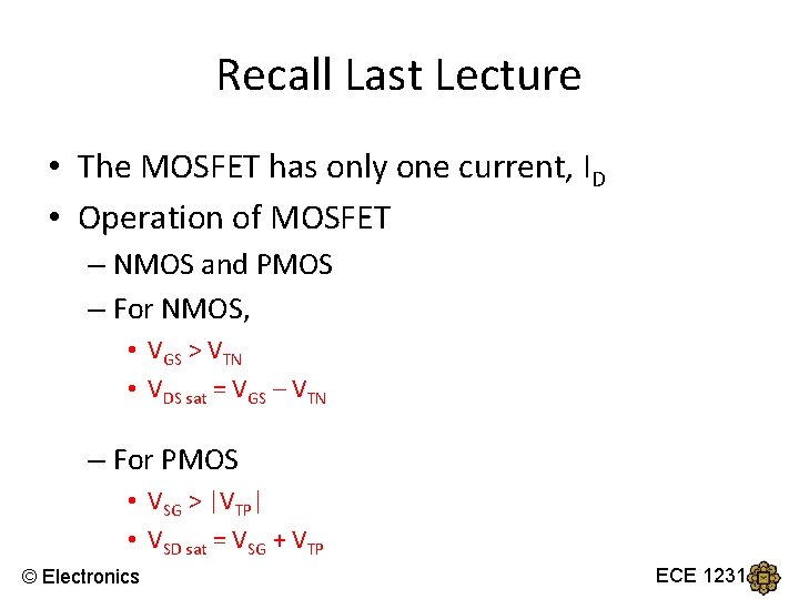
Recall Last Lecture • The MOSFET has only one current, ID • Operation of MOSFET – NMOS and PMOS – For NMOS, • VGS > VTN • VDS sat = VGS – VTN – For PMOS • VSG > |VTP| • VSD sat = VSG + VTP © Electronics ECE 1231
• ID versus VDS (NMOS) or ID versus VSD (PMOS) © Electronics ECE 1231
• NMOS • PMOS o VTN is POSITIVE o VGS > VTN to turn on o Triode/non-saturation region o VTP is NEGATIVE o VSG > |VTP| to turn on o Triode/non-saturation region o Saturation region o VDSsat = VGS - VTN o VSDsat = VSG + VTP © Electronics ECE 1231
DC analysis of FET © Electronics ECE 1231
MOSFET DC Circuit Analysis - NMOS Ø The source terminal is at ground and common to both input and output portions of the circuit. Ø The CC acts as an open circuit to dc but it allows the signal voltage to the gate of the MOSFET. Ø In the DC equivalent circuit, the gate current into the transistor is zero, the voltage at the gate is given by a voltage divider principle: VG = VTH = R 2 VDD R 1 + R 2 Use KVL at GS loop: VGS –VTH + 0 = 0 VGS = VTH © Electronics ECE 1231
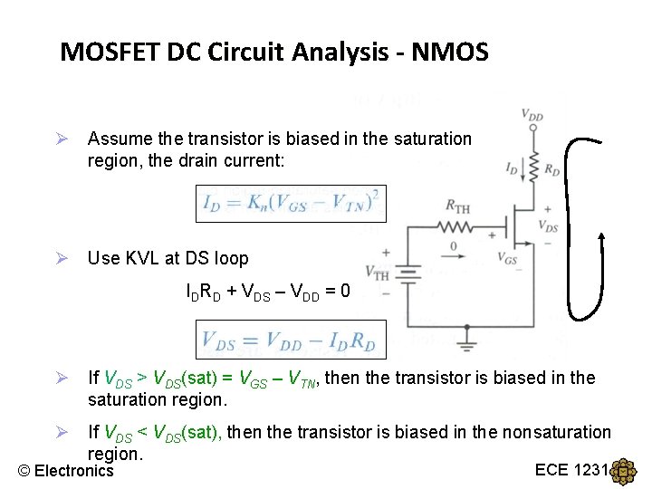
MOSFET DC Circuit Analysis - NMOS Ø Assume the transistor is biased in the saturation region, the drain current: Ø Use KVL at DS loop IDRD + VDS – VDD = 0 Ø If VDS > VDS(sat) = VGS – VTN, then the transistor is biased in the saturation region. Ø If VDS < VDS(sat), then the transistor is biased in the nonsaturation region. © Electronics ECE 1231
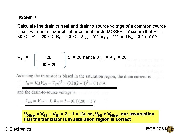
EXAMPLE: Calculate the drain current and drain to source voltage of a common source circuit with an n-channel enhancement mode MOSFET. Assume that R 1 = 30 k , R 2 = 20 k , RD = 20 k , VDD = 5 V, VTN = 1 V and Kn = 0. 1 m. A/V 2 VTH = 20 5 = 2 V hence VGS = VTH = 2 V 30 + 20 VDSsat = VGS – VTN = 2 – 1 = 1 V, so, VDS > VDSsat, our assumption that the transistor is in saturation region is correct © Electronics ECE 1231
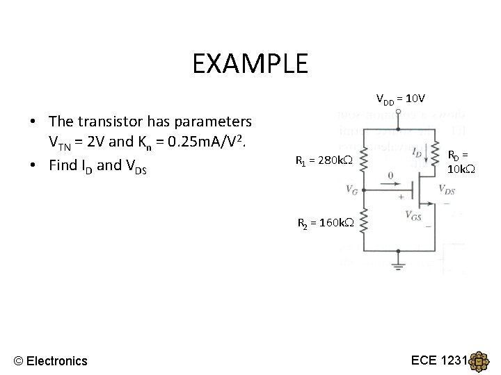
EXAMPLE VDD = 10 V • The transistor has parameters VTN = 2 V and Kn = 0. 25 m. A/V 2. • Find ID and VDS R 1 = 280 k RD = 10 k R 2 = 160 k © Electronics ECE 1231
Solution 1. VTH = 160 10 = 3. 636 V 160 + 280 KVL at GS loop: VGS – VTH + 0 = 0 VGS = VTH 2. Assume in saturation mode: ID = Kn(VGS - VTN)2 So, ID = 0. 669 m. A 3. KVL at DS loop: VDS = VDD – IDRD = 10 – 0. 669 (10) = 3. 31 V 4. VDS sat = VGS – VTN = 3. 636 – 2 = 1. 636 V So, VDS > VDSsat , therefore, assumption is correct! Answer: ID = 0. 669 m. A and VDS = 3. 31 V © Electronics ECE 1231
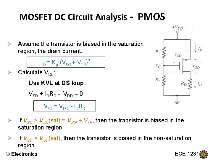
MOSFET DC Circuit Analysis - PMOS Different notation: VSG and VSD Threshold Voltage = VTP VG = VTH = R 2 VDD R 1 + R 2 Use KVL at GS loop: VSG + 0 + VTH – VDD = 0 VSG = VDD - VTH © Electronics ECE 1231
MOSFET DC Circuit Analysis - PMOS Ø Assume the transistor is biased in the saturation region, the drain current: ID = Kp (VSG + VTP)2 Ø Calculate VSD: Use KVL at DS loop: VSD + IDRD - VDD = 0 VSD = VDD - IDRD Ø If VSD > VSD(sat) = VSG + VTP, then the transistor is biased in the saturation region. Ø If VSD < VSD(sat), then the transistor is biased in the non-saturation region. © Electronics ECE 1231
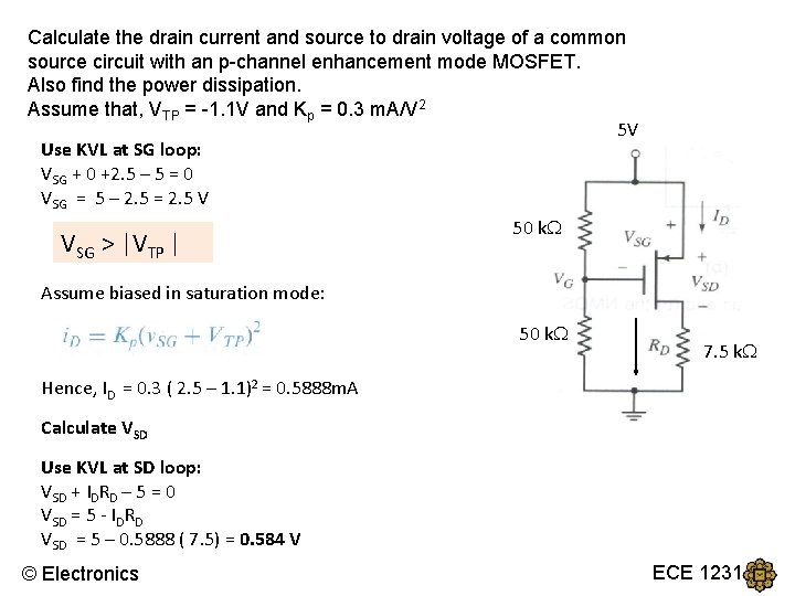
Calculate the drain current and source to drain voltage of a common source circuit with an p-channel enhancement mode MOSFET. Also find the power dissipation. Assume that, VTP = -1. 1 V and Kp = 0. 3 m. A/V 2 5 V Use KVL at SG loop: VSG + 0 +2. 5 – 5 = 0 VSG = 5 – 2. 5 = 2. 5 V VSG > |VTP | 50 k Assume biased in saturation mode: 50 k 7. 5 k Hence, ID = 0. 3 ( 2. 5 – 1. 1)2 = 0. 5888 m. A Calculate VSD Use KVL at SD loop: VSD + IDRD – 5 = 0 VSD = 5 - IDRD VSD = 5 – 0. 5888 ( 7. 5) = 0. 584 V © Electronics ECE 1231
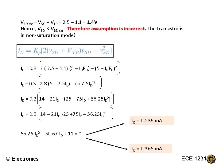
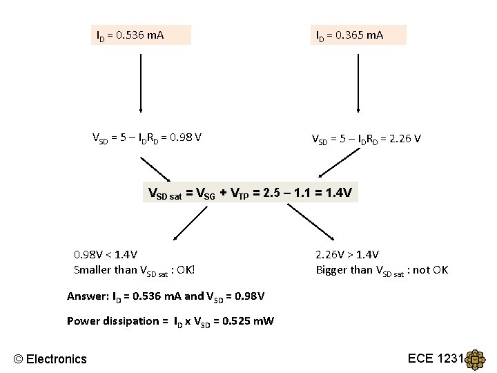
VSD sat = VSG + VTP = 2. 5 – 1. 1 = 1. 4 V Hence, VSD < VSD sat. Therefore assumption is incorrect. The transistor is in non-saturation mode! ID = 0. 3 2 ( 2. 5 – 1. 1) (5 – IDRD) – (5 – IDRD)2 ID = 0. 3 2. 8 (5 – 7. 5 ID) – (5 -7. 5 ID)2 ID = 0. 3 14 – 21 ID – (25 – 75 ID + 56. 25 ID 2) ID = 0. 3 14 – 21 ID -25 +75 ID – 56. 25 ID 2 ID = 0. 536 m. A 56. 25 ID 2 – 50. 67 ID + 11 = 0 ID = 0. 365 m. A © Electronics ECE 1231
ID = 0. 536 m. A VSD = 5 – IDRD = 0. 98 V ID = 0. 365 m. A VSD = 5 – IDRD = 2. 26 V VSD sat = VSG + VTP = 2. 5 – 1. 1 = 1. 4 V 0. 98 V < 1. 4 V Smaller than VSD sat : OK! 2. 26 V > 1. 4 V Bigger than VSD sat : not OK Answer: ID = 0. 536 m. A and VSD = 0. 98 V Power dissipation = ID x VSD = 0. 525 m. W © Electronics ECE 1231
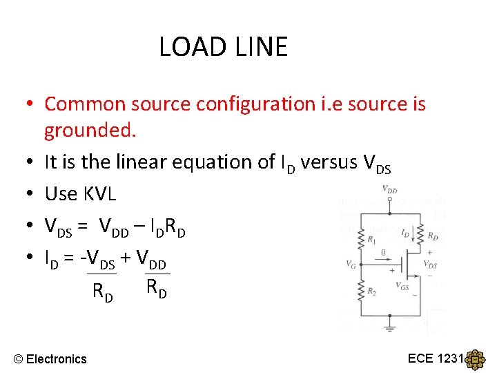
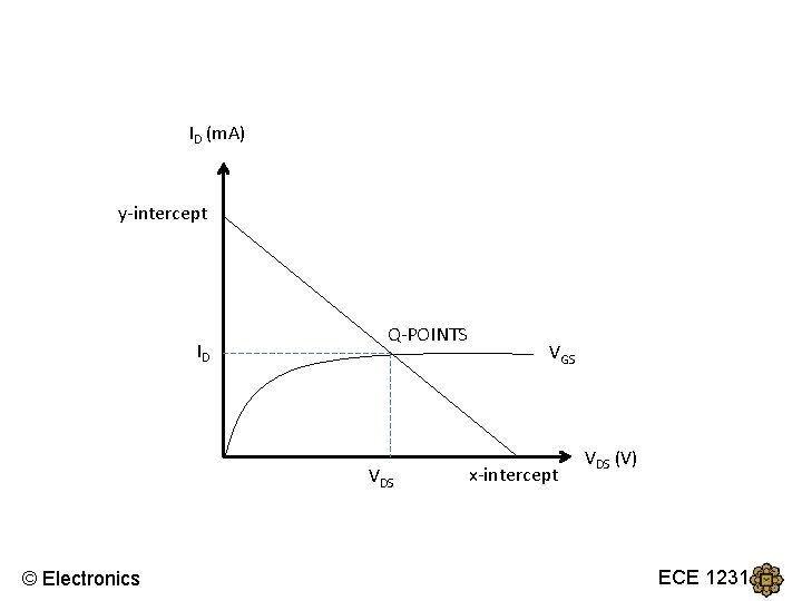
LOAD LINE • Common source configuration i. e source is grounded. • It is the linear equation of ID versus VDS • Use KVL • VDS = VDD – IDRD • ID = -VDS + VDD RD RD © Electronics ECE 1231
ID (m. A) y-intercept ID Q-POINTS VDS © Electronics VGS x-intercept VDS (V) ECE 1231
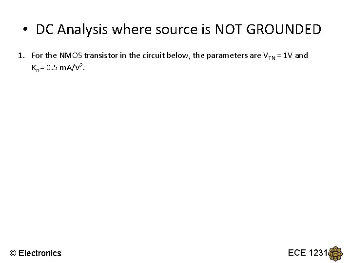
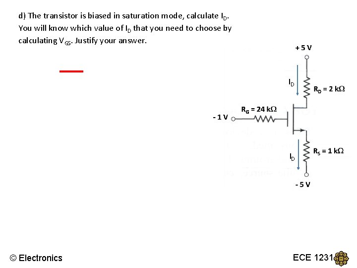
• DC Analysis where source is NOT GROUNDED 1. For the NMOS transistor in the circuit below, the parameters are VTN = 1 V and Kn = 0. 5 m. A/V 2. © Electronics ECE 1231
a) What is the value of VG ? VG = -1 V b) Write down the branch current equation for the source terminal. ID c) Get an expression for VGS in terms of ID use KVL: 0 + VGS+ 1(ID) -5 +1 = 0 VGS = 4 - ID Or use node voltages: VGS = VG - VS VGS = -1 – ( ID – 5) ID VGS = 4 - ID © Electronics ECE 1231
d) The transistor is biased in saturation mode, calculate ID. You will know which value of ID that you need to choose by calculating VGS. Justify your answer. ID ID © Electronics ECE 1231
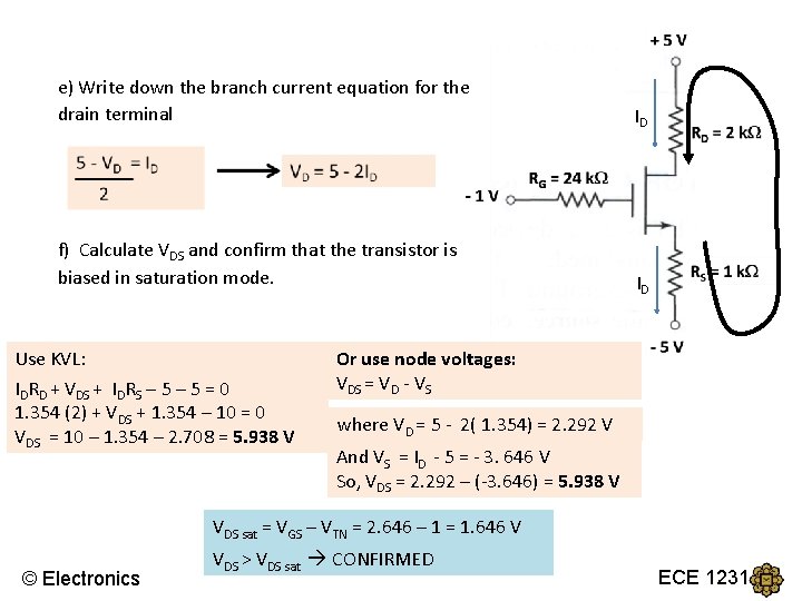
e) Write down the branch current equation for the drain terminal ID f) Calculate VDS and confirm that the transistor is biased in saturation mode. ID Use KVL: IDRD + VDS + IDRS – 5 = 0 1. 354 (2) + VDS + 1. 354 – 10 = 0 VDS = 10 – 1. 354 – 2. 708 = 5. 938 V Or use node voltages: VDS = VD - VS where VD = 5 - 2( 1. 354) = 2. 292 V And VS = ID - 5 = - 3. 646 V So, VDS = 2. 292 – (-3. 646) = 5. 938 V VDS sat = VGS – VTN = 2. 646 – 1 = 1. 646 V © Electronics VDS > VDS sat CONFIRMED ECE 1231