Chapter 9 INSTRUCTION SET ARCHITECTURE Computer Architecture Concepts

 – Binary Assembly language (Assembly dili) –")


![Three-address Instructions X=(A+B)(C+D) ADD T 1, A, B M[T 1] M[A] + M[B] ADD](https://slidetodoc.com/presentation_image_h2/9e7dfe7fb090e79b76ad1cd64beb7e31/image-7.jpg "Three-address Instructions X=(A+B)(C+D) ADD T 1, A, B M[T 1] M[A] + M[B] ADD")
![Two-address Instructions X=(A+B)(C+D) MOVE T 1, A M[T 1] M[A] ADD T 1, B](https://slidetodoc.com/presentation_image_h2/9e7dfe7fb090e79b76ad1cd64beb7e31/image-8.jpg "Two-address Instructions X=(A+B)(C+D) MOVE T 1, A M[T 1] M[A] ADD T 1, B")
![One-address Instructions X=(A+B)(C+D) LD A ACC M[A] ADD B ACC + M[B] ST X](https://slidetodoc.com/presentation_image_h2/9e7dfe7fb090e79b76ad1cd64beb7e31/image-9.jpg "One-address Instructions X=(A+B)(C+D) LD A ACC M[A] ADD B ACC + M[B] ST X")
(C+D) To perform an ADD instruction with zero address, all three addresses")
![Zero-address Instructions X=(A+B)(C+D) PUSH A TOS M[A] PUSH B TOS M[B] TOS + TOS-1](https://slidetodoc.com/presentation_image_h2/9e7dfe7fb090e79b76ad1cd64beb7e31/image-11.jpg "Zero-address Instructions X=(A+B)(C+D) PUSH A TOS M[A] PUSH B TOS M[B] TOS + TOS-1")


x. C+(Dx. E) Identical Postfix expression AB+Cx. DEx+ PUSH A PUSH B")


- Slides: 27
Chapter 9 INSTRUCTION SET ARCHITECTURE
Computer Architecture Concepts Machine language (Makine dili) – Binary Assembly language (Assembly dili) – Symbolic The manuals list all hardware-implemented instructions, specify the symbolic names and binary code format of the instructions, and provide a architecture of the computer A computer usually has a variety of instructions and multiple instruction formats. It is the function of the control unit to decode each instruction and provide the control signals needed to process it.
Computer Architecture Concepts The format of an instruction is depicted in rectangular box symbolizing the bits of the binary instruction. The bits are divided into groups called fields. Typical fields; 1. An opcode field, which specifies the operation to be performed 2. An address field, which provides either a memory or an address for selecting a processor register 3. A mode field, which specifies the way the address field is to be interpreted.
Basic Computer Operation Cycle 1. Fetch the instruction from memory into a control register 2. Decode the instruction 3. Locate the operands used by the instruction 4. Fetch operands from memory (if necessary) 5. Execute the operation in processor registers 6. Store the results in the proper place 7. Go back to step 1 to fetch next instruction PC: Program counter
Register Set: Consists of all registers in the CPU that are accessible to the programmer Processor Status register (PSR); Status values C, N, V, Z from ALU Stack pointer (SP) Hidden registers: • Instruction register • Registers in register file that are accesible only to microprograms • Pipeline registers
Operand Addressing Implied address : Ex. INC R 0 Explicit address : Ex ADD R 0, R 1, R 2 Sample arithmetic statement X=(A+B)(C+D)
Three-address Instructions X=(A+B)(C+D) ADD T 1, A, B M[T 1] M[A] + M[B] ADD T 2, C, D M[T 2] M[C] + M[D] MUL X, T 1, T 2 M[X] M[T 1] x M[T 2] Registers as a temporary register ADD R 1, A, B M[R 1] M[A] + M[B] ADD R 2, C, D M[R 2] M[C] + M[D] MUL X, R 1, R 2 M[X] M[R 1] x M[R 2] • Short programs for evaluating expression • Binary coded instruction require more bits to specify three address, particularly if they are memory address
Two-address Instructions X=(A+B)(C+D) MOVE T 1, A M[T 1] M[A] ADD T 1, B M[T 1] + M[B] MOVE X, C M[X] M[C] ADD X, D M[X] + M[D] MUL X, T 1 M[X] x M[T 1] • Requires 5 instruction instead of three • T 1 can be replaced with R 1
One-address Instructions X=(A+B)(C+D) LD A ACC M[A] ADD B ACC + M[B] ST X M[X] ACC LD C ACC M[C] ADD D ACC + M[D] MUL X ACC x M[X] ST X M[X] ACC • ACC, Accumulator ; • All operations are done between the ACC and memory operand • Requires 7 instruction instead of three
Zero-address Instructions X=(A+B)(C+D) To perform an ADD instruction with zero address, all three addresses in the instruction must be implied. A conventional way of achieving this goal is to use structure referred to as stack. last in, first out (LIFO); son giren ilk çıkar Data manupulation operations are performed on the stack. TOS : Top Of the Stack TOS-1: below TOS PUSH : loads the stack PUSH X TOS M[X] POP : Extract data from stack POP X M[X] TOS
Zero-address Instructions X=(A+B)(C+D) PUSH A TOS M[A] PUSH B TOS M[B] TOS + TOS-1 ADD PUSH C TOS M[C] PUSH D TOS M[D] ADD TOS + TOS-1 MUL TOS x TOS-1 POP X M[X] TOS
Addressing Architectures The programs just presented will change if the number of address to the memory in the instructions is restricted or if the memory address are restricted to specify instructions. These restrictions, combined with the number of operands addressed, define the addressing architectures. Memory-to-memory architecture: All operands come directly from memory, and all results are send directly to memory For previous example, 3 instruction are required, but if an extra word must appear in the instruction for each memory address, then up to four memory reads are required to fetch each instruction. Including the fetching of operands, storing of results, the program to perform the addition would require 21 access to memory. Even though the instruction count is low, the execution time is potentially high. Complex hardware. Typically not used in the new design.
Addressing Architectures Three address Register-to-register or Load/Store Architecture. Allows only one memory address and restricts its use to load and store types of instructions, is typically in modern processors. X=(A+B)(C+D) LD R 1, A R 1 M[A] LD R 2, B R 2 M[B] ADD R 3, R 1, R 2 R 3 R 1 + R 2 LD R 1, C R 1 M[C] LD R 2, D R 2 M[D] ADD R 1, R 2 R 1 + R 2 MUL R 1, R 3 R 1 x R 2 ST X, R 1 M[B] R 1 Total 8 instruction require 18 access to memory
Addressing Architectures Register-memory Architecture Two address instructions with a single memory ADD R 1, A R 1 + M[A] The program lenghts and number of memory access tend to be intermediate between the previous two architecture Single accumulator architecture This architecture has no register file, its single address is for accessing memory. It requires 21 access to memory to evaluate the “X=(A+B)(C+D)” In more complex programs, significiant additional memory access would be needed for temporary storage locations in memory. Because of its large number of memory access, this architecture is inefficient and, is restricted to use in CPU’s for simple, low-cost applications that don’t require high performance.
Addressing Architectures Stack architecture Zero address instruction case Since most of the stack is located in memory , one or more memory access may be reqıired for stack operations. A register-register and load/store architectures have made strong performace advances, the high frequancy of memory access in stack architectures has made them unattractive. Stack architectures are compatible with a very efficient approach to expresssion processing which uses postfix notation rather than the traditional infix notation Infix expression (A+B)x. C+(Dx. E) Identical Postfix expression AB+Cx. DEx+
Infix expression (A+B)x. C+(Dx. E) Identical Postfix expression AB+Cx. DEx+ PUSH A PUSH B ADD PUSH C MUL PUSH D PUSH E MUL ADD
PUSH A PUSH B ADD PUSH C MUL PUSH D PUSH E MUL ADD
ADDRESSING MODES Effective address Copmuters use addressing-mode techniques to accommodate one or both of the following provisions: 1. 2. To give programming flexibility to the user via pointers to memory, counters for loop control, indexing of data, and relocation of programs To reduce the number of bits in the address fields of the instruction The availability of various addressing modes gives the experianced programmer the ability to write programs that require fewer instruction
ADDRESSING MODES Implied mode Needs no address field. In this mode , the operand is specified implicitly in the definition of the opcode For example “complement accumulator” is an impliedmode instruction Immediate mode The operand specified in the instruction itself. An immadiate mode instruction has an operand field rather than an address field. Ex. Initializing registers to a constant value.
ADDRESSING MODES Register and register-indirect modes Address field of the instruction may specify either a memory location (register indirect mode) or a processor register (register mode). Before using register indirect mode instruction, the programmer must ensure that the memory address is available in the processor register. Autoincrement or autodecrement mode is similar to register-indirect mode, except that the register is incremented or decremented after (or before) , ts address value is used to access memory. ADD (R 1)+, 3 M[R 1] + 3, R 1+1 R 1 isi initialized to address the first element in the array. 3 ADD instruction can be executed repeatedly.
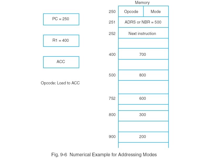
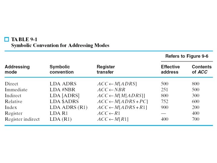
ADDRESSING MODES Direct addressing mode Address field of the instruction gives the address of the operand in memory in a data transfer or data manupulation instruction. ACC M[ADRS]
ADDRESSING MODES Direct addressing mode for Branch type instructions
ADDRESSING MODES Indirect addressing mode Address field of the instruction gives the address at which the effective address is stored in memory ADRS=500 M[ADRS]=800 ACC M[800]
ADDRESSING MODES Relative addressing mode Effective address=contents of PC + Address part of instruction PC=250 ADRS=500 PC=252+500=752
ADDRESSING MODES Index addressing mode The content of an index register is added to the address part oıf the instruction to obtain the effective address Index register may be special CPU register or simply a register in register file. PC=250 ADRS=500 PC=252+500=752