Simplified Instructional Computer SIC SIC Architecture Two versions
")
. SIC program can be")


 are")
 • Integer arithmetic")

 Additional Registers")


: immediate")

 •")

 SIC instruction sets SIC/XE instruction sets Use immediate mode will")
 BETA <- (ALPHA + INCR - 1) DELTA <-")
 This program will execute faster because it need not")
")
 This program will execute faster because TIXR need not")
![SIC Programming Example (4. a) Gamma [] <- Alpha [] + Beta []](https://slidetodoc.com/presentation_image/3d3d458253985f629dcb1c561cc4ea20/image-27.jpg "SIC Programming Example (4. a) Gamma [] <- Alpha [] + Beta []")
 This program will execute faster because it uses register-to-register")

 Read 100 words into the record buffer")
 Use TIXR makes this program run faster")
- Slides: 31
Simplified Instructional Computer (SIC)
SIC Architecture • Two versions: SIC and SIC/XE (extra equipments). SIC program can be executed on SIC/XE. • Memory consists of 8 -bit bytes. 3 consecutive bytes form a word (24 bits) • In total, there are 2^15 bytes in the memory. • There are 5 registers. Each is 24 bits in length.
Five Registers
Data Format • Integers are stored as 24 -bit binary numbers; 2’s complement representation is used for negative numbers. • Characters are store using their 8 -bit ASCII codes. • There is no floating-point hardware on SIC.
Instruction Format • All machine instructions on SIC has the following 24 -bit format. X is used to indicate indexed-addressing mode.
Addressing Modes • Only two modes are supported: – Direct – Indexed () are used to indicate the content of a register.
Instruction Set • Load and store registers (LDA, LDX, STA, STX) • Integer arithmetic (ADD, SUB, MUL, DIV), all involve register A and a word in memory. • Comparison (COMP), involve register A and a word in memory. • Conditional jump (JLE, JEQ, JGT, etc. ) • Subroutine linkage (JSUB, RSUB)
Input and Output • One byte at a time to or from the rightmost 8 bits of register A. • Each device has a unique 8 -bit ID code. • Test device (TD): test if a device is ready to send or receive a byte of data. • Read data (RD): read a byte from the device to register A • Write data (WD): write a byte from register A to the device.
SIC/XE Architecture • Memory: 1 megabytes (2^20 bytes) Additional Registers
Data Format • The same as that of SIC. • There is a floating-point data type with the following format: Between 0 and 1 Must be 1 • The value represented by the above format is (-1)^s * f * 2 ^(e – 1024)
Instruction Formats e=0 e=1
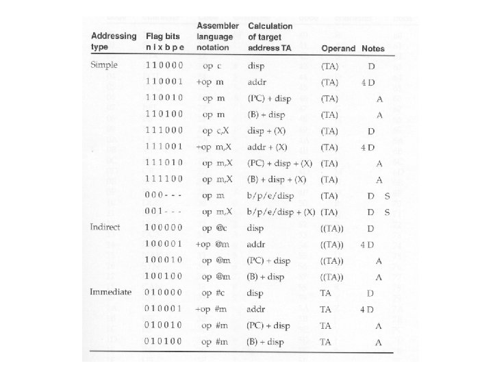
Addressing Mode • Two additional modes are introduced format 3: In format 3, if both bits b and p are set to 0, the disp (or address) is taken as the target address. This is called direct addressing mode. Both modes can be combined with indexed addressing – if bit x is set to 1, the value of register X is added in the target Address calculation.
Addressing Modes For format 3 and 4: • (i =1, n = 0): immediate addressing mode. The target address is used as the operand. • (i = 0, n = 1): indirect addressing mode. The word at the location given by the target address is fetched; the value contained in this word is then used as the address of the operand value. • (i = 0, n = 0) used by SIC, (i=1, n=1) used by SIC/XE: simple addressing mode. The target address is taken as the location of the operand. Indexing mode cannot be used with immediate or indirect modes.
Example All of these instructions are LDA.
Instruction Set • LDB and STB • Floating-point operations (ADDF, SUBF, MULF, DIVF) • Register move (RMO) • Register-to-register operations (ADDR, SUBR, MULR, DIVR) • Supervisor call (SVC) for generating system calls into the operating system. • I/O channel operation (SIO: start, TIO: test, HIO: halt), similar to DMA.
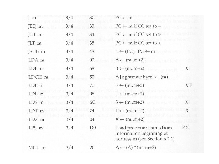
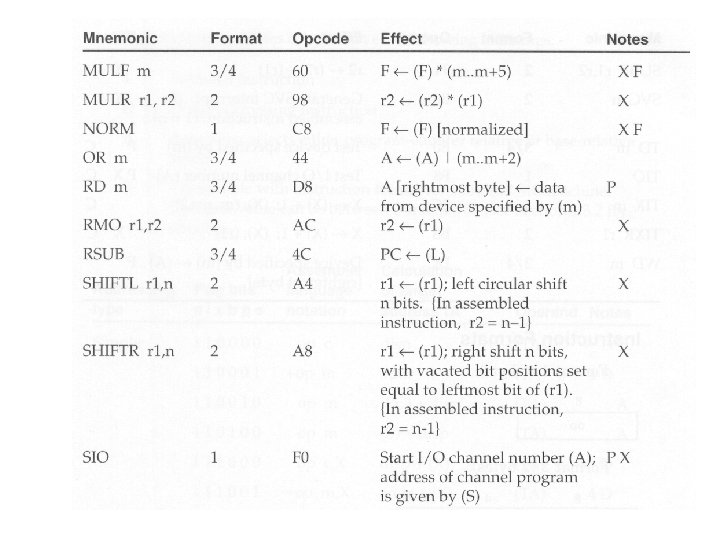
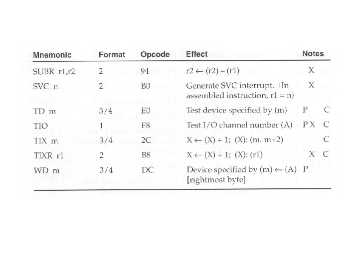
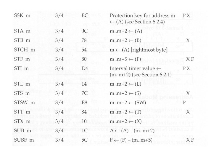
Complete Instruction Set P: privileged instruction X: available Only on XE F: floating. Point Instruction C: condition code CC set to indicate result of operation
SIC Programming Example (1) SIC instruction sets SIC/XE instruction sets Use immediate mode will make the program run faster because it need not fetch five from the memory.
SIC Programming Example (2. a) BETA <- (ALPHA + INCR - 1) DELTA <- (GAMMA + INCR - 1)
SIC Programming Example (2. b) This program will execute faster because it need not load INCR from memory each time when INCR is needed.
SIC Programming Example (3. a)
SIC Programming Example (3. b) This program will execute faster because TIXR need not compare the index value to a memory variable.
SIC Programming Example (4. a) Gamma [] <- Alpha [] + Beta []
SIC Programming Example (4. b) This program will execute faster because it uses register-to-register add to reduce memory accesses.
Input and Output Examples
Subroutine Call Example (5. a) Read 100 words into the record buffer
Subroutine Call Example (5. b) Use TIXR makes this program run faster