Cement Grouting Grouting Pressure 2 to 4 kgcm


 • Guniting machine complying requirements given in IS")


- Slides: 28
Cement Grouting • Grouting Pressure 2 to 4 kg/cm 2 • W/c ratio 0. 4 to 0. 5 • Admixture to impart non-shrinkable properties and to improve flowability of grout may be added with approval of Divisional Engineer
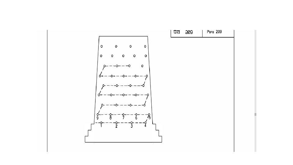
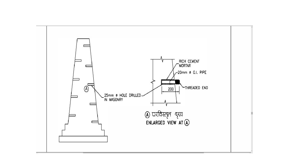
Procedure of Cement Grouting • Holes are drilled in structure along cracks and in and around hollow spots • Spacing of holes 500 to 750 mm covering adequately the area proposed to be grouted. Holes spacing can be altered as per site condition • GI pipes ( 12 mm to 20 mm dia x 200 mm long) with one end threaded are fixed in the holes with rich cement mortar • All the cracks are cut open to a V groove and cleaned • All the cracks and annular space around GI pipes are sealed with rich cement mortar
Procedure of Cement Grouting • All grout holes should be sluiced with water using same equipment a day before grouting so as to saturate masonry • All holes are first plugged with wooden plugs • The bottom most plug 1 and two adjacent plugs 2 and 9 are removed and water injected in the hole 1 under pressure. • When the clear water comes out of holes 2 & 9 , the injection of water is stopped and holes 1 & 9 are plugged • The procedure is repeated with holes 2, 3 & 8 etc till all holes are covered.
Procedure of Cement Grouting • On the day of grouting all plugs are removed to drain out water and re-plugged before commencing grouting. • The same sequence as above is followed for groutinmg also. • After grouting curing is done for 14 days and tell tales are provided. • Only such quantities of grout that can be used within 15 minutes of mixing should be prepared
Epoxy Grouting • • • As compared to CG , EG is quick setting Low shrinkage High strength Low viscosity enables it to penetrate fine cracks Good resistance to chemicals Much more Expensive, should be used only it is techno economically justified
Epoxy Grouting • Composition of EG: ØConsists of epoxy resin and a hardener which react chemically when mixed ØBy suitably proportioning of the mix of resin, hardener and thinner ( if necessary) , the viscosity of the mix can be varied to suit all type of conditions ØGrouting of wide cracks requires large quantity of grout material, in such cases suitable fillers e. g. dry silicon flour etc can be added based on manufacturers recommendation
Epoxy Grouting • Specification of EG : Ø Considering the width, depth and extent of cracks and other relevant details, the viscosity of resin hardener mix, their proportions, pot life, application procedure etc. Should be chosen in consultation with the manufacturer ØThe shear strength on a specimen of MS plates should not be less than 100 kg/cm 2 ØEpoxy mortar should not be susceptible to fire and explosion during injection and must be stable under varying climatic conditions
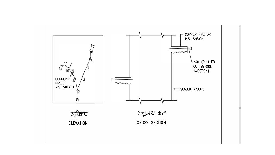
Procedure for Epoxy grouting • The area to be grouted should be dry and free from oil, grease , dust and all loose materials • All cracks should be cut open to a V groove about 10 mm deep. Loose material should be removed by compressed air and groove fully sealed using epoxy modified mortar at least one day in advance • Holes of 7 -10 mm dia are drilled along the cracks and copper or aluminium or polyethylene pipe pieces of 6 -9 mm dia fixed as grout nipples • Epoxy is injected from the bottom most pipe, keeping all other pipes, except the adjacent ones , blocked by wooden plugs. Injection is done at pressure of 3. 5 to 7 kg per sq. Cm
Procedure for Epoxy grouting • As soon as epoxy comes out from adjacent open pipes, they are plugged and the pressure increased to the desired level and maintained for 2 to 3 minutes • The injection nozzle is then withdrawn and the hole sealed with epoxy mortar • This procedure is repeated for other pipes also • Due to restricted pot life , it is advisable to mix only small quantities of epoxy at a time. • Low viscosity resins should be adopted for thin cracks • A record of materials consumed should be maintained
Precautions While Handling Epoxy Resins • Manufacture’s detailed instructions should be followed for safe handling and processing • Direct skin contact should be avoided • The gun syringe should be washed with acetone immediately after use
GUNITINF/SHOTCRETING
• Shotcrete has been generally referred as sprayed concrete, spraycrete, gunite, pneumatically applied mortar or concrete, air-blown mortar or concrete and gunned concrete. • Indian and American standards term this concrete as shotcrete, whereas European standards term as sprayed concrete • Shotcrete is defined by IS 9012 and ACI 506 R as “mortar or concrete conveyed through a hose and pneumatically projected at high velocity onto a surface” • There are two processes for shotcreting: Dry mix process and wet mix process • Dry mix shotcrete: process in which most of water is added at nozzle. Normally in India this process is referred as Gunite. Cement Sand mix is used generally used in dry mix process, though concrete can also be used. • Wet mix shotcrete: process in which all ingredients including water are added before pushing the material to delivery hose. • https: //www. youtube. com/watch? v=-qljr. F 5 BGpg (short film on shotcrete)
Materials : • IS 9012 mentions that all the materials for shotcrete shall be complied with the respective Indian standards for particular materials such as cement, aggregates, water, admixture and reinforcement. However, this code doesn’t mention min and max limits of constituent materials like cement. • The minimum and maximum limits of materials should be determined as per relevant standards ( IR CBC for bridge works and IS 456 for other concrete works)
Minimum Cement Content • As per IS 456, the minimum cement content varies with respect to compressive strength and exposure conditions. • The limiting values for cement content related to exposure conditions as recommended by IS 456 are as below: The minimum cement requirement as per CBC is as below: • ACI 506 R suggests cementitious content range from 390 to 450 kg/m 3
Fine aggregate : • The use of finer sand will generally result in greater drying shrinkage and coarser sand in more rebound. The Indian standard suggests that sand for shotcrete shall grade evenly from fine to coarse as per Zone II and Zone III grading of IS 383 Coarse aggregate: • IS code suggests that coarse aggregate shall conform to one of the grading with nominal maximum aggregate size of 10, 12. 5 and 20 mm as illustrated in Table I of IS 9012 • As per CBC , Coarse aggregate should conform to IS : 383, with a maximum nominal size of 10 to 12. 5 mm • However, international codes such as ACI 506 R specifies 10 mm max aggregate size. • In practice also it is observed that aggregate size should be limited to 10 mm.
Fine and coarse aggregate ratio: • Coarse aggregate to fine aggregate ratio is one of the most important parameters in shotcrete mix design. • The Indian standard does not include the proportioning of coarse and fine aggregate. • ACI 506 R specifies total aggregate will consists of 20% to 30% coarse aggregate and 70 to 80% fine aggregate Water Cementitious Ratio: • The water cementitious (w/cm) ratio should be as low as possible to achieve high strength and durable shotcrete • The Indian standard specifies a maximum w/cm of 0. 5
Execution Of Shotcrete Preparation of surface : • All weathered or deteriorated material should be removed until the surface exposed is sound to receive the Shotcrete • The surface should be cleaned of all loose and foreign materials with an air/water jet. • If the joint mortar is weak, the joint should be raked to about 10 mm depth and all loose, dry mortar scraped out. • Exposed reinforcement should be cleaned free of rust, scale etc. and given a coat of neat cement or any other anti-corrosive material. • Porous surface should be kept damp for several hours before shotcreting.
Form work : • The forms where required shall be plywood or other suitable material set true to line and dimension. • They should be adequately braced and constructed so as to permit the escape of air and rebound during the shotcreting operation (particularly in the case of thick members)
Reinforcement : • Depending on the thickness and nature of the work; reinforcement may consist of either round bars, or welded wire fabric 3 mm diameter( IS 1566) • Sufficient clearance should be provided around the reinforcement. The minimum clearance between the reinforcement and form or other back up material may vary between 12 mm for the mortar mix and wire fabric reinforcement to 50 mm for the concrete mix and 16 mm dia reinforcing bars. • However, the minimum cover for reinforcement shall be as per CBC / IS : 456. The minimum wire mesh spacing should be 50 mm by 50 mm. Clear spacing between bars should be at least 65 mm. • For repair work, the reinforcement should be fixed to existing masonry by wiring to nails driven into the masonry and rigidly secured
Equipment required (Annexure 2/9 of IRBM) • Guniting machine complying requirements given in IS : 6433. • Air Compressor with a capacity of 10 cum/per minute and which can develop a pressure of upto 7 kg/cm 2. • Placing nozzle with hose. • Uniform air pressure is maintained at the nozzle outlet. For lengths of hose upto 30 m, the air pressure is 3 kg/cm 2 or more. For longer lengths the pressure is increased by 0. 35 kg/cm 2 for each additional 15 m of hose and by 0. 35 kg/cm 2 for each staging of 7. 5 m that the nozzle is raised above the gun.
Typical Dry Mix Guniting Machine Annexure 2/9 of IRBM
Placing : • The total thickness of gunite required should be built up in a number of layers with an interval of about 4 hours. • Each layer is built up by making several passes or loops of the nozzle over the working area. • The distance of the nozzle from the work, usually between 0. 5 and 1. 5 m, should be such as to give the best results. • Particular care should be taken when gunning through and encasing reinforcing bars. (For walls, columns and beams, the application should begin at the bottom). • In guniting slabs, the nozzle should be held at a slight angle so that the rebound is blown on to the completed portion
Rebound : • The rebound is mortar or concrete which bounces off the surface during the application. • Rebound should not be worked back into the construction and should be rejected. • Before laying additional layer, the first layer should be allowed to take its initial set. Then all laitance, loose material and rebound should be removed. • The surface should be tested with a hammer for dummy areas which should be carefully cut out and replaced with the succeeding layer. • Curing : • The surfaces should be kept continuously wet for at least 7 days.
• Shotcreting by the wet process requires special equipment and can be used for building up thick layer. • For further details reference can be made to • IS : 9012 "Recommended Practice for shotcreting”
THANKS