National Technical Seminar IPWE India Use of Modern


- Slides: 28

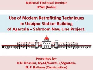
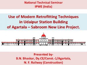
National Technical Seminar IPWE (India) Use of Modern Retrofitting Techniques in Udaipur Station Building of Agartala – Sabroom New Line Project. Presented by. B. N. Bhaskar, Dy. CE/Const. -1/Agartala, N. F. Railway (Construction)

LIST OF CONTENTS Ø INTRODUCTION. Ø HISTORY OF PROBLEMS. Ø REMEDIAL MEASURES. Ø STRATEGY FOR RETROFITTING. Ø METHODOLOGY OF RETROFITTING. Ø CONCLUSIONS.

INTRODUCTION • Udaipur railway station of Agartala-Sabroom New BG Line Project is situated between Km. 42. 2 to 43. 3 (Km. 0. 00 at Agartala) in the state of Tripura. • Station is situated in the Sukhsagar Lake of Udaipur. o Water logged and marshy soil. o Existence of soft soil (Silty Clay) upto 13. 3 m depth. o Out of 13. 3 m top 8 m is mixed with decomposed trees & wooden logs. • During construction of building differential settlement of piles. • Retrofitting of the building was done and now the building is functional. • Agartala – Udaipur section was opened on 28. 09. 2016.

Location of Udaipur Station Building Sukhsagar Lake Udaipur Station

HISTORY OF THE PROBLEM FORMATION IN STATION YARD: • Construction started in Dec’ 2010. • Huge Settlement in the range of 1 to 2 m was noticed in Oct' 2011 when construction height reached 3 m. • The work continued & reached to a height of 5 m. • Huge Settlement, Cracks and Heaving of adjacent ground beyond toe (upto 25 m on both sides of embankment).

HISTORY OF THE PROBLEM STATION BUILDING: • Earth filling started in Nov’ 2011. • Pile foundation started in Dec’ 2011. • Pile foundation completed by Nov’ 2012. • Differential settlement observed in Pile cap No. 13, 14 and 35 in May 2012 and cracks noticed in plinth beam and grade beams connected to above mentioned pile caps. • Brickwork for wall done in Jan’ 2014 and differential settlement increased further.

REMEDIAL MEASURES • Ground soil improvement of the adjoining area by Pre -fabricated Vertical Drain (PVD) for accelerating consolidation of soft soil. • Sheet piling of adequate retaining capacity around the station building before stripping off the existing surrounding embankment for PVD installation. • Retrofitting of the station building by providing additional pile raft system and Carbon Fibre Reinforced Polymer (CFRP).

STRATEGY FOR RETROFITTING 1) Addition of structures • Additional piles in each room and near to failed piles. • Provision of suspended slab. 2) Withdrawal of filled up soil between plinth beam and pile cap 3) Strengthening of structures by using Carbon Fibre Reinforced Polymer. • Grade beam • Plinth beam • Columns

METHODOLOGY OF RETROFITTING ADDITION OF PILES • Installation of Additional two number of cast in situ 600 mm dia RCC piles of 25 m length in each room. • In case of differential settlement of piles, major portion of the load will be transferred to these piles through the new beam connecting existing plinth beam and new pile cap.

METHODOLOGY OF RETROFITTING INSTALLATION OF 600 MM RCC PILES AND MAKING OF PILE CAP

METHODOLOGY OF RETROFITTING CONNECTING THE NEW PILE CAP WITH THE EXISTING PLINTH BEAMS BY NEW BEAMS TO TRANSFER THE LOAD TO THE NEW PILES

METHODOLOGY OF RETROFITTING ADDITION OF SUSPENDED SLAB • Introducing new structural slab, integrated with plinth beams, columns and new pile cap. • This slab would behave as suspended slab as the filled soil is removed. (Gap between suspended slab and finish ground level is reducing the overburden load and may be used for services. ). • Integrating suspended slab with plinth beam in such a way that it acts as a single entity.

METHODOLOGY OF RETROFITTING ADDITIONAL REINFORCEMENT FOR PLINTH BEAM CONNECTING SUSPENDED SLAB WITH PLINTH BEAM AND COLUMNS

METHODOLOGY OF RETROFITTING REINFORCEMENT READY FOR SUSPENDED SLAB CASTING

METHODOLOGY OF RETROFITTING STRENGTHENING OF GRADE BEAM, PLINTH BEAM AND COLUMNS: • Grade Beams by Carbon Fibre wrapping. • Plinth Beams by fixing the Carbon Laminate and by Carbon Fibre wrapping. • Columns by Carbon Fibre wrapping

METHODOLOGY OF RETROFITTING GRINDING OF GRADE BEAM AND PLINTH BEAM To smoothen the concrete surface Plinth Beam Grade Beam

METHODOLOGY OF RETROFITTING APPLICATION OF POLYMER MODIFIED MORTAR (PMM) TO THE BOTTOM OF PLINTH BEAMS As a leveling course to make good the undulations in the bottom of beams.

METHODOLOGY OF RETROFITTING GROUTING OF CRACKS WITH MONOPOL CHEMICAL To fill the cracks (Grouting pressure: 3 -5 Kg/cm 2) Fixing of Nozzle Monopole Chemical Grouting Machine

METHODOLOGY OF RETROFITTING APPLICATION OF PRIMER COAT OVER THE BEAM SURFACE To fill the surface voids RESIN PRIMER APPLICATION OF PUTTY – As leveling course PUTTY APPLICATION

METHODOLOGY OF RETROFITTING CARBON FIBRE LAMINATE : PHYSICAL PROPERTIES: MECHANICAL PROPERTIES: • Materials- Carbon-80%, • Laminate Tensile Strength Resin-20%, 1800 Mpa • Density-1. 6 gm/cc • Laminate Tensile Elastic Modulus-150 GPa • Laminate width-100 mm and Thickness-2. 4 mm

METHODOLOGY OF RETROFITTING Fixing of carbon laminate to the plinth beams in 80% length Fixing of Laminate to the Plinth Beam bottom FIXING OF ANCHOR PLATE To provide firm fixidity of Laminate with plinth beam bottom Fixing of Anchor plate to Plinth beam

METHODOLOGY OF RETROFITTING CARBON FIBRE Physical Properties: • Materials: Carbon content -99%, Thermo glass yarn -1% • Carbon Fibre wrap width-500 mm • Carbon Fibre Thickness - 0. 44 mm Mechanical Properties: • Carbon Fibre Tensile Strength – 4100 Mpa • Carbon Fibre Tensile Modulus - 250 GPa

METHODOLOGY OF RETROFITTING CARBON FIBRE WRAPPING OF THE GRADE BEAM, PLINTH BEAM AND COLUMN Ø Confines the concrete • Enhances compressive strength of concrete. • Improves shear strength of concrete. • Improves ductility of structural elements. • Arrests the crack propagation in the beams.

METHODOLOGY OF RETROFITTING CARBON FIBRE WRAPPING

METHODOLOGY OF RETROFITTING FIXING OF CARBON FIBRE ANCHOR To have intact bond between beam and carbon fibre (Spacing 300 mm c/c) Carbon Fibre Anchor SECOND COAT OF EPOXY OVER THE CARBON FIBER WRAPPING To protect from weathering action

CONCLUSIONS • Initially when construction was carried out, the condition of soil was poor and initial consolidation settlement caused distress. • Piling and filling of soil work were done simultaneously which resulted into negative skin friction. • Retrofitting of station building aimed at deriving the adequate lateral capacity for earthquake resistance and to strengthen for the applicable loads, forces and effects.

• The creation of strong diaphragm by structural slab and beams along with additional Piles/ Pile Cap also helped in arresting differential settlement. • The retrofitting of station building includes the state of art techniques by using CFRP wrap, Carbon Fiber Anchors, Carbon Laminates etc, for strengthening Grade Beams, Columns, Plinth beams which makes the system very strong and durable. • Overall, following capacities were enhanced by doing retrofitting. § Shear capacity. § Flexural capacity of beam. § Load bearing capacity of Columns and Foundations. § Ductility and Seismic capacity.

THANK YOU
 Ipwe udaipur
 Seminar on education in india
 National training seminar
 Trends in india foreign trade
 Nths cord
 National technical systems fullerton
 Donetsk technical university
 Kharkiv national technical university
 National research center for career and technical education
 National archives of india
 National intervention programme for mother and child
 National innovation council india
 National 4 history
 National 5 modern languages talking performance
 National unification and the national state
 Yesterday
 What makes a good college application
 What is smart note taker
 Miami pediatric nephrology seminar
 Ap seminar memes
 W seminar präsentation
 Buck boost transformer seminar report
 Ap seminar iwa word count minimum
 Level 3 questions examples
 Socratic seminar sentence frames
 Types of seminar method
 Sop acara
 Define socratic seminar
 Definition of socratic seminar
