C 802 20 0329 Smart Antenna and MCSCDMA

- Slides: 39
C 802. 20 -03/29 Smart Antenna and MC-SCDMA Next Generation Technologies for Wireless Broadband Guanghan Xu, CTO Navini Networks 15 September 2020 April, 12 2001 1
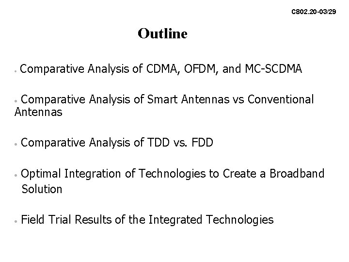
C 802. 20 -03/29 Outline • Comparative Analysis of CDMA, OFDM, and MC-SCDMA Comparative Analysis of Smart Antennas vs Conventional Antennas • • Comparative Analysis of TDD vs. FDD Optimal Integration of Technologies to Create a Broadband Solution Field Trial Results of the Integrated Technologies
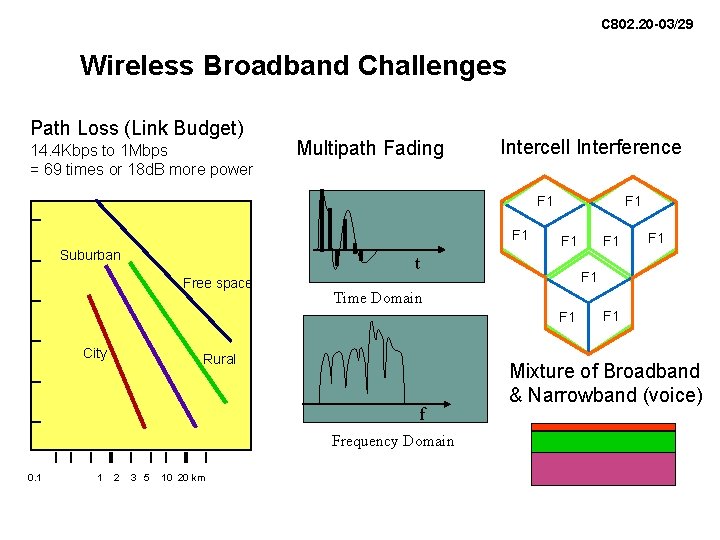
C 802. 20 -03/29 Wireless Broadband Challenges Path Loss (Link Budget) 14. 4 Kbps to 1 Mbps = 69 times or 18 d. B more power Multipath Fading Intercell Interference F 1 Suburban F 1 t Free space Time Domain Rural f Frequency Domain 0. 1 1 2 3 5 10 20 km F 1 F 1 City F 1 Mixture of Broadband & Narrowband (voice)
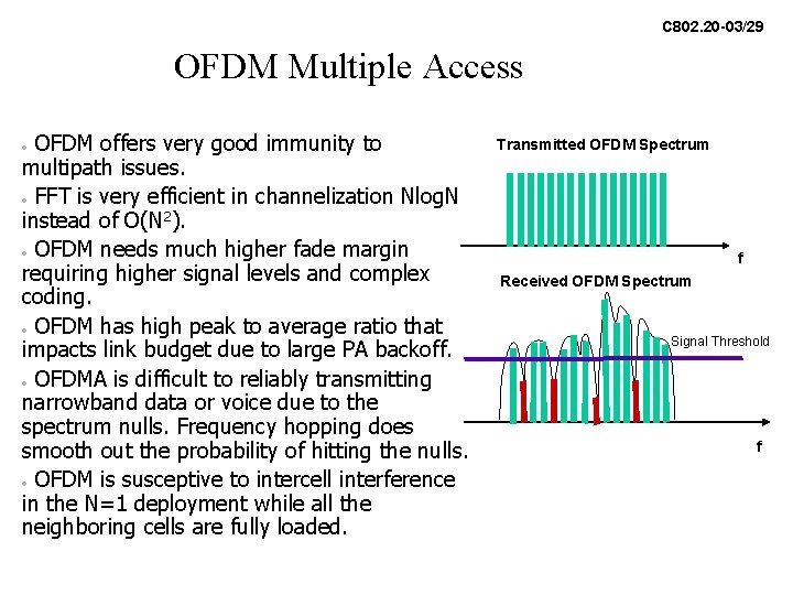
C 802. 20 -03/29 OFDM Multiple Access OFDM offers very good immunity to multipath issues. • FFT is very efficient in channelization Nlog. N instead of O(N 2). • OFDM needs much higher fade margin requiring higher signal levels and complex coding. • OFDM has high peak to average ratio that impacts link budget due to large PA backoff. • OFDMA is difficult to reliably transmitting narrowband data or voice due to the spectrum nulls. Frequency hopping does smooth out the probability of hitting the nulls. • OFDM is susceptive to intercell interference in the N=1 deployment while all the neighboring cells are fully loaded. • Transmitted OFDM Spectrum f Received OFDM Spectrum Signal Threshold f
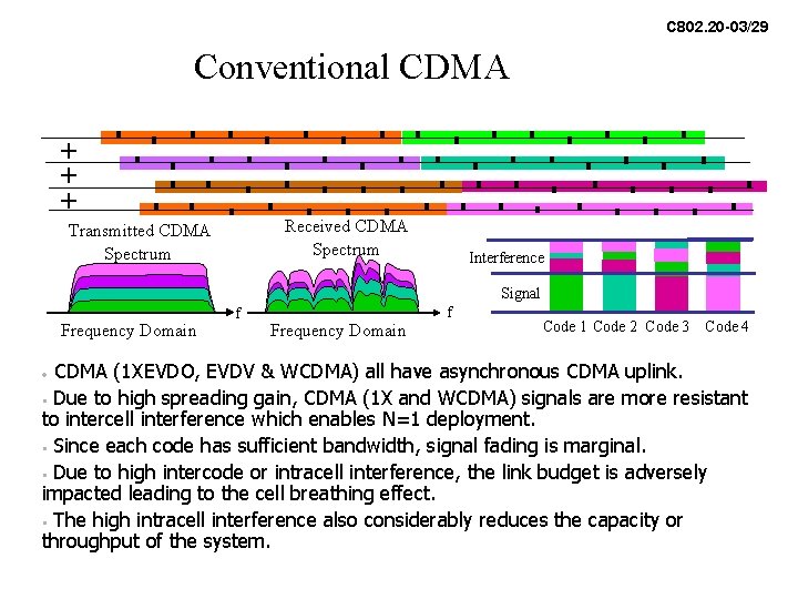
C 802. 20 -03/29 Conventional CDMA + + + Received CDMA Spectrum Transmitted CDMA Spectrum Interference Signal Frequency Domain f Code 1 Code 2 Code 3 Code 4 CDMA (1 XEVDO, EVDV & WCDMA) all have asynchronous CDMA uplink. • Due to high spreading gain, CDMA (1 X and WCDMA) signals are more resistant to intercell interference which enables N=1 deployment. • Since each code has sufficient bandwidth, signal fading is marginal. • Due to high intercode or intracell interference, the link budget is adversely impacted leading to the cell breathing effect. • The high intracell interference also considerably reduces the capacity or throughput of the system. •
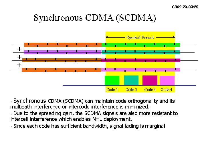
C 802. 20 -03/29 Synchronous CDMA (SCDMA) Symbol Period + + + Code 1 • Code 2 Code 3 Code 4 Synchronous CDMA (SCDMA) can maintain code orthogonality and its multipath interference or intercode interference is minimized. • Due to the spreading gain, the SCDMA signals are also more resistant to intercell interference which enables N=1 deployment. • Since each code has sufficient bandwidth, signal fading is marginal.
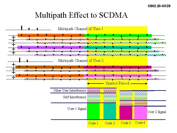
C 802. 20 -03/29 Multipath Effect to SCDMA Multipath Channel of User 1 + + + + + Multipath Channel of User 2 Symbol Period Other User Interference Self Interference User 1 Signal User 2 Signal Code 1 Code 2 Code 3 Code 4
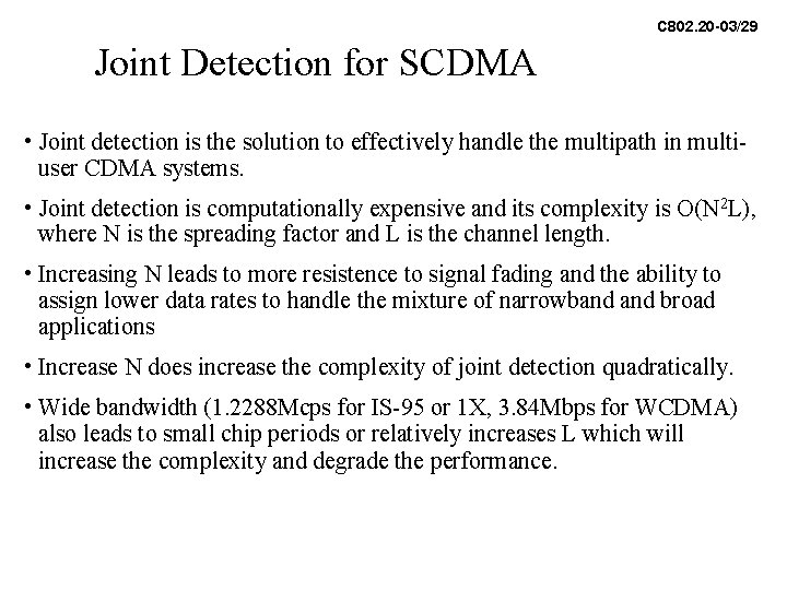
C 802. 20 -03/29 Joint Detection for SCDMA • Joint detection is the solution to effectively handle the multipath in multiuser CDMA systems. • Joint detection is computationally expensive and its complexity is O(N 2 L), where N is the spreading factor and L is the channel length. • Increasing N leads to more resistence to signal fading and the ability to assign lower data rates to handle the mixture of narrowband broad applications • Increase N does increase the complexity of joint detection quadratically. • Wide bandwidth (1. 2288 Mcps for IS-95 or 1 X, 3. 84 Mbps for WCDMA) also leads to small chip periods or relatively increases L which will increase the complexity and degrade the performance.
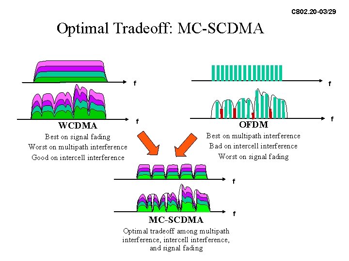
C 802. 20 -03/29 Optimal Tradeoff: MC-SCDMA f f f WCDMA OFDM Best on multipath interference Bad on intercell interference Worst on signal fading Best on signal fading Worst on multipath interference Good on intercell interference f MC-SCDMA Optimal tradeoff among multipath interference, intercell interference, and signal fading f f
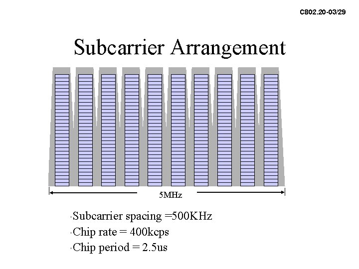
C 802. 20 -03/29 Subcarrier Arrangement 5 MHz Subcarrier spacing =500 KHz • Chip rate = 400 kcps • Chip period = 2. 5 us •
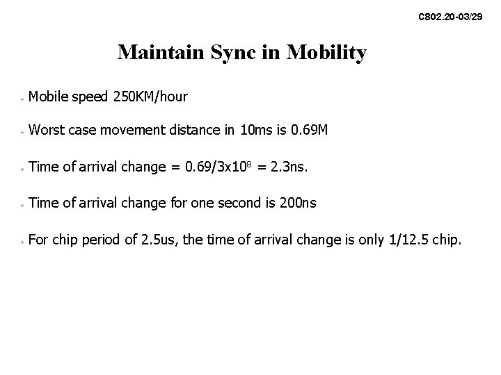
C 802. 20 -03/29 Maintain Sync in Mobility • Mobile speed 250 KM/hour • Worst case movement distance in 10 ms is 0. 69 M • Time of arrival change = 0. 69/3 x 108 = 2. 3 ns. • Time of arrival change for one second is 200 ns • For chip period of 2. 5 us, the time of arrival change is only 1/12. 5 chip.
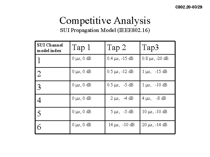
C 802. 20 -03/29 Competitive Analysis SUI Propagation Model (IEEE 802. 16) SUI Channel model index Tap 1 Tap 2 Tap 3 1 0 ms, 0 d. B 0. 4 ms, -15 d. B 0. 8 ms, -20 d. B 2 0 ms, 0 d. B 0. 5 ms, -12 d. B 1 ms, -15 d. B 3 0 ms, 0 d. B 0. 5 ms, -5 d. B 1 ms, -10 d. B 4 0 ms, 0 d. B 2 ms, -4 d. B 4 ms, 5 0 ms, 0 d. B 5 ms, -5 d. B 10 ms, -10 d. B 6 0 ms, 0 d. B 14 ms, -10 d. B 20 ms, -14 d. B -8 d. B
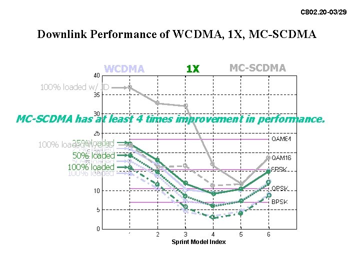
C 802. 20 -03/29 Downlink Performance of WCDMA, 1 X, MC-SCDMA WCDMA 1 X MC-SCDMA 100% loaded w/ JD MC-SCDMA has at least 4 times improvement in performance. 25%W/O loaded 100% loaded JD 25% loaded 50% loaded 100% loaded Sprint Model Index
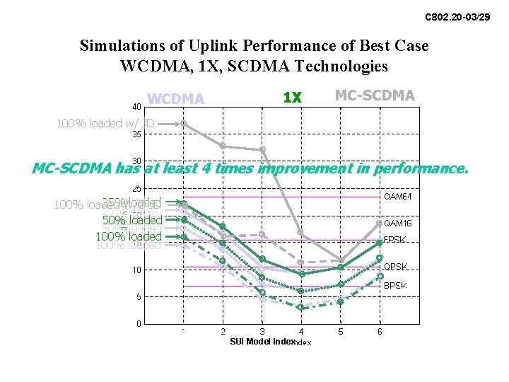
C 802. 20 -03/29 Simulations of Uplink Performance of Best Case WCDMA, 1 X, SCDMA Technologies WCDMA 1 X MC-SCDMA 100% loaded w/ JD MC-SCDMA has at least 4 times improvement in performance. 25%W/O loaded 100% loaded JD 25% loaded 50% loaded 100% loaded SUI Model Index
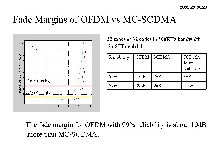
C 802. 20 -03/29 Fade Margins of OFDM vs MC-SCDMA 32 tones or 32 codes in 500 KHz bandwidth for SUI model 4 95% reliability Reliability OFDM SCDMA Joint Detection 95% 13 d. B 7 d. B 8 d. B 99% 20 d. B 9 d. B 11 d. B 99% reliability The fade margin for OFDM with 99% reliability is about 10 d. B more than MC-SCDMA.
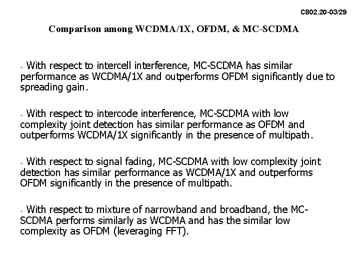
C 802. 20 -03/29 Comparison among WCDMA/1 X, OFDM, & MC-SCDMA With respect to intercell interference, MC-SCDMA has similar performance as WCDMA/1 X and outperforms OFDM significantly due to spreading gain. • With respect to intercode interference, MC-SCDMA with low complexity joint detection has similar performance as OFDM and outperforms WCDMA/1 X significantly in the presence of multipath. • With respect to signal fading, MC-SCDMA with low complexity joint detection has similar performance as WCDMA/1 X and outperforms OFDM significantly in the presence of multipath. • With respect to mixture of narrowband broadband, the MCSCDMA performs similarly as WCDMA and has the similar low complexity as OFDM (leveraging FFT). •
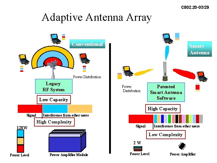
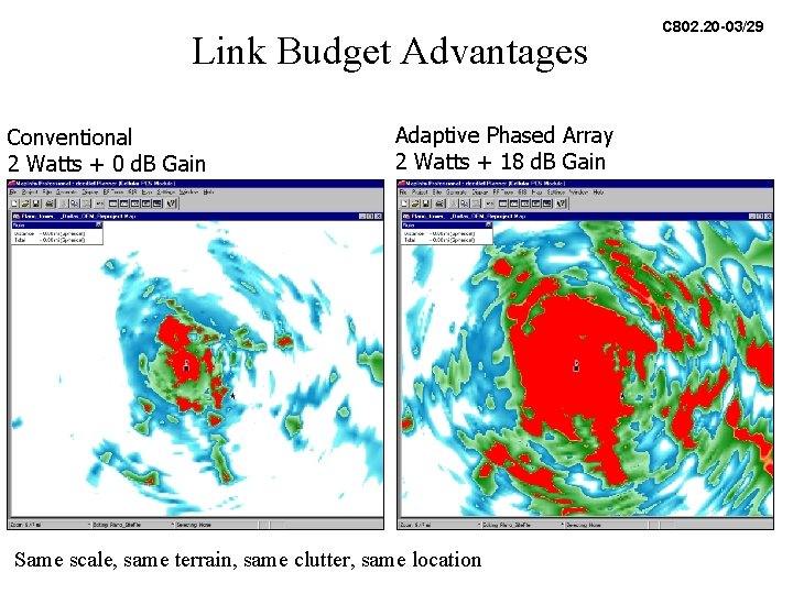
C 802. 20 -03/29 Adaptive Antenna Array Conventional Smart Antenna Power Distribution Legacy RF System Patented Smart Antenna Software Power Distribution Low Capacity High Capacity Signal Interference from other users High Complexity 128 W Signal Interference from other users Low Complexity 2 W Power Level Power Amplifier Module Power Level Power Amplifier
Link Budget Advantages Conventional 2 Watts + 0 d. B Gain Adaptive Phased Array 2 Watts + 18 d. B Gain Same scale, same terrain, same clutter, same location C 802. 20 -03/29
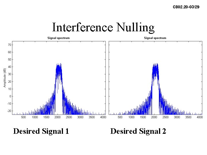
C 802. 20 -03/29 Interference Nulling Desired Signal 1 Desired Signal 2
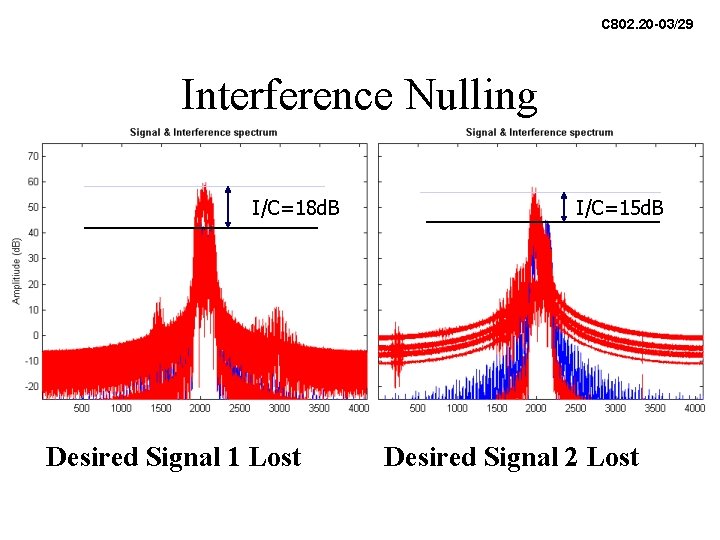
C 802. 20 -03/29 Interference Nulling I/C=18 d. B Desired Signal 1 Lost I/C=15 d. B Desired Signal 2 Lost
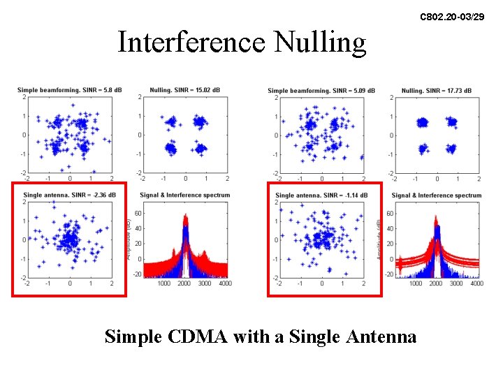
C 802. 20 -03/29 Interference Nulling Simple CDMA with a Single Antenna
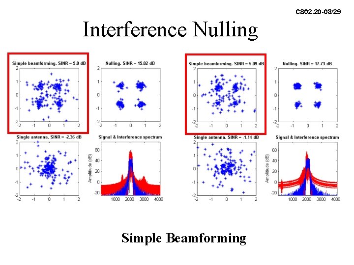
C 802. 20 -03/29 Interference Nulling Simple Beamforming
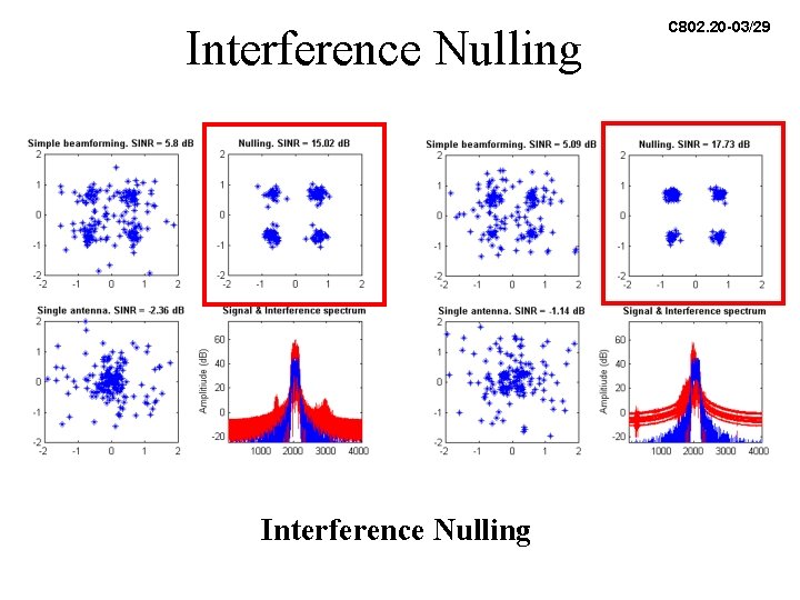
Interference Nulling C 802. 20 -03/29
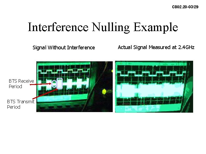
C 802. 20 -03/29 Interference Nulling Example Signal Without Interference BTS Receive Period BTS Transmit Period Actual Signal Measured at 2. 4 GHz
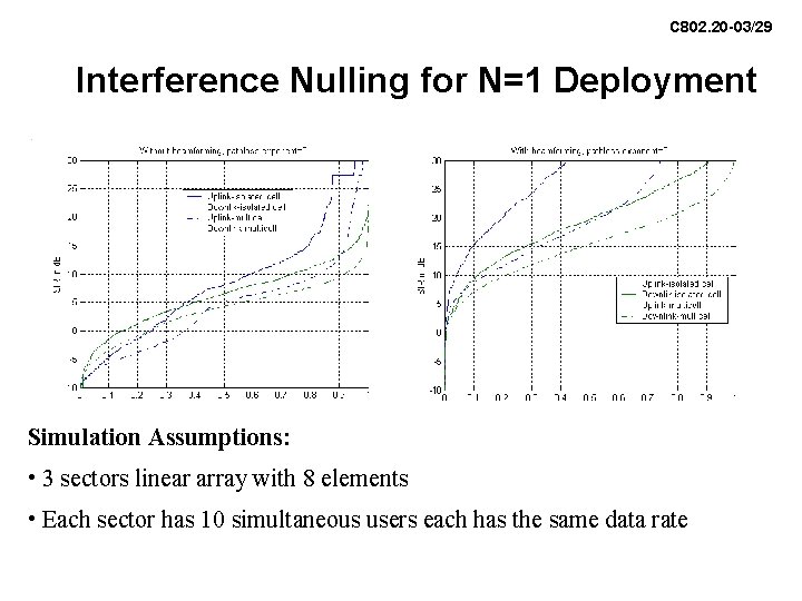
C 802. 20 -03/29 Interference Nulling for N=1 Deployment Simulation Assumptions: • 3 sectors linear array with 8 elements • Each sector has 10 simultaneous users each has the same data rate
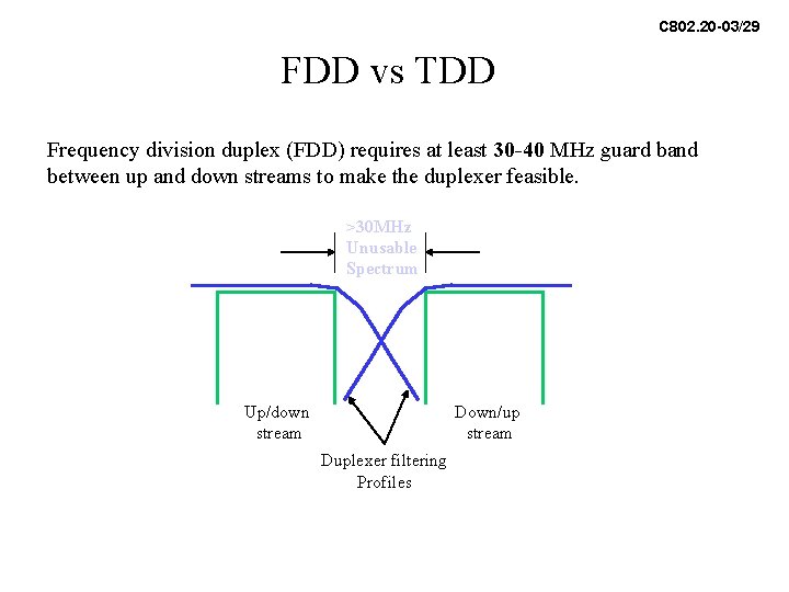
C 802. 20 -03/29 FDD vs TDD Frequency division duplex (FDD) requires at least 30 -40 MHz guard band between up and down streams to make the duplexer feasible. >30 MHz Unusable Spectrum Up/down stream Down/up stream Duplexer filtering Profiles
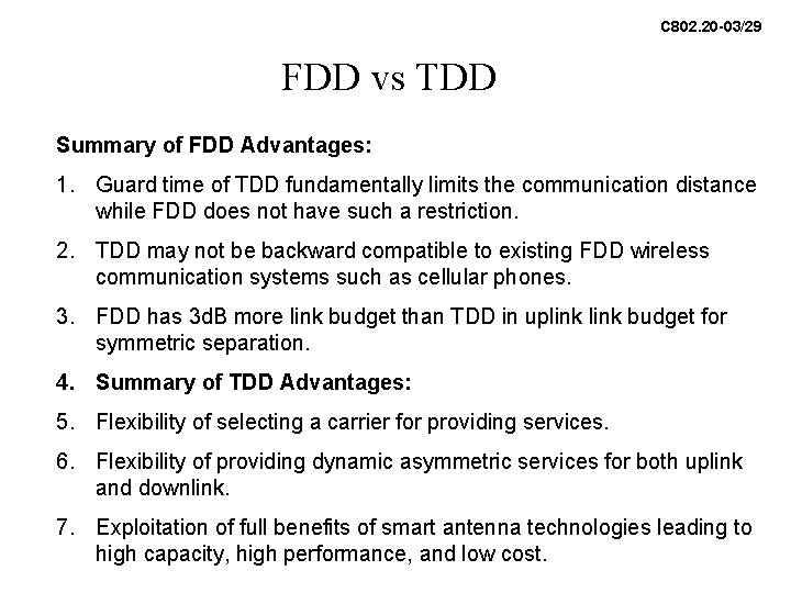
C 802. 20 -03/29 FDD vs TDD Summary of FDD Advantages: 1. Guard time of TDD fundamentally limits the communication distance while FDD does not have such a restriction. 2. TDD may not be backward compatible to existing FDD wireless communication systems such as cellular phones. 3. FDD has 3 d. B more link budget than TDD in uplink budget for symmetric separation. 4. Summary of TDD Advantages: 5. Flexibility of selecting a carrier for providing services. 6. Flexibility of providing dynamic asymmetric services for both uplink and downlink. 7. Exploitation of full benefits of smart antenna technologies leading to high capacity, high performance, and low cost.
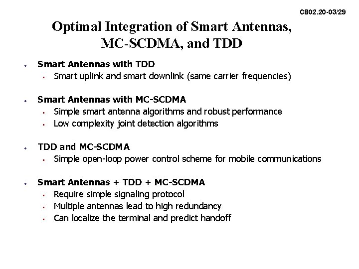
C 802. 20 -03/29 Optimal Integration of Smart Antennas, MC-SCDMA, and TDD • • Smart Antennas with TDD • Smart uplink and smart downlink (same carrier frequencies) Smart Antennas with MC-SCDMA • Simple smart antenna algorithms and robust performance • Low complexity joint detection algorithms TDD and MC-SCDMA • Simple open-loop power control scheme for mobile communications Smart Antennas + TDD + MC-SCDMA • Require simple signaling protocol • Multiple antennas lead to high redundancy • Can localize the terminal and predict handoff
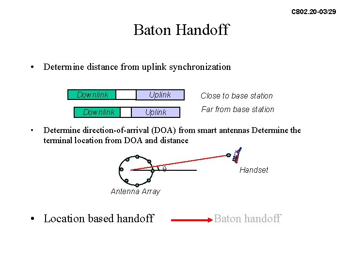
C 802. 20 -03/29 Baton Handoff • Determine distance from uplink synchronization Downlink Uplink Downlink • Uplink Close to base station Far from base station Determine direction-of-arrival (DOA) from smart antennas Determine the terminal location from DOA and distance q Handset Antenna Array • Location based handoff Baton handoff
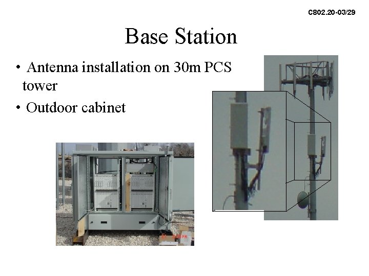
C 802. 20 -03/29 Base Station • Antenna installation on 30 m PCS tower • Outdoor cabinet
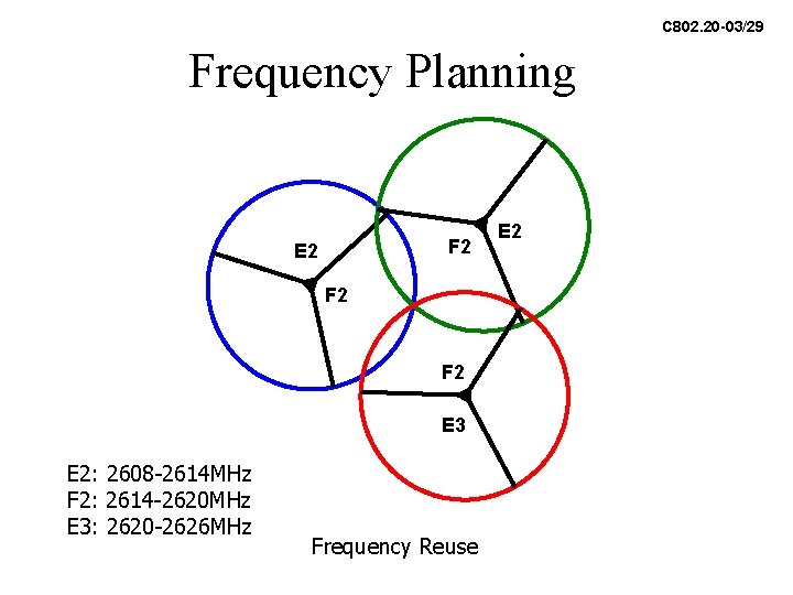
C 802. 20 -03/29 Frequency Planning F 2 E 2 F 2 E 3 E 2: 2608 -2614 MHz F 2: 2614 -2620 MHz E 3: 2620 -2626 MHz Frequency Reuse E 2
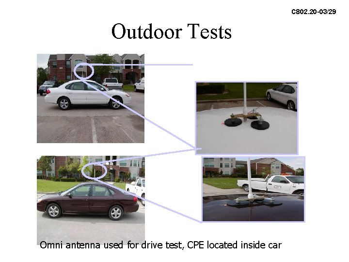
C 802. 20 -03/29 Outdoor Tests Omni antenna used for drive test, CPE located inside car
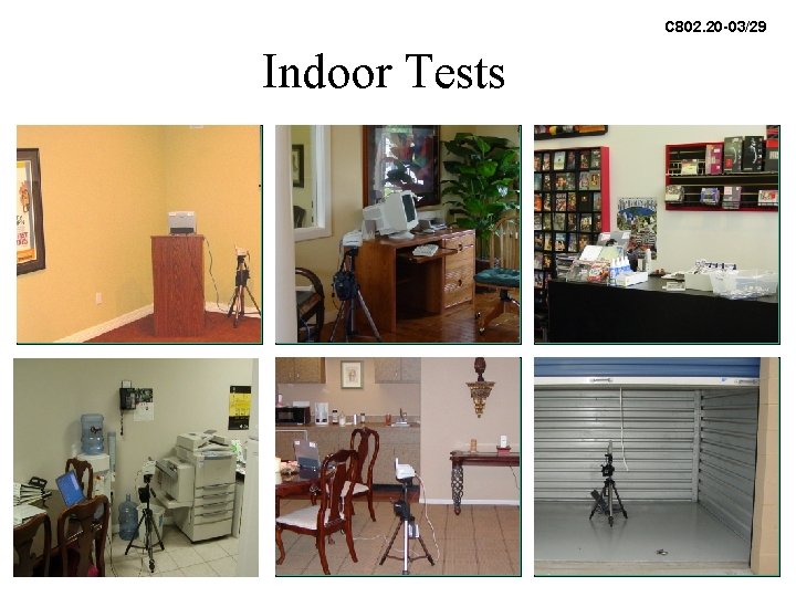
C 802. 20 -03/29 Indoor Tests
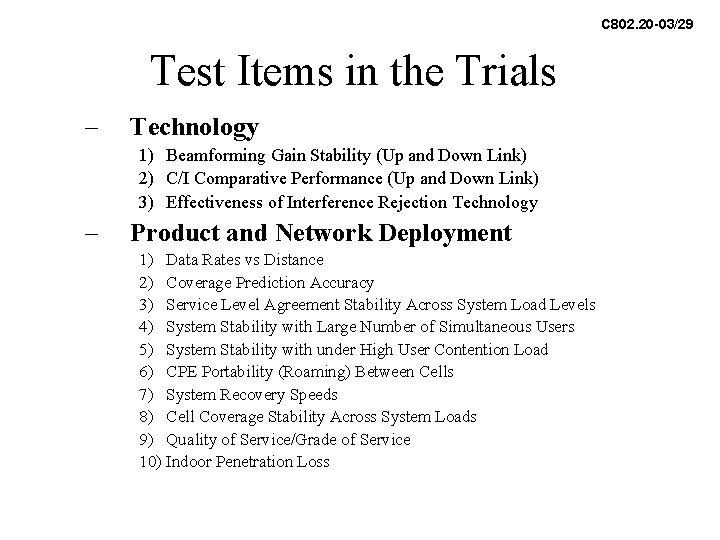
C 802. 20 -03/29 Test Items in the Trials – Technology 1) Beamforming Gain Stability (Up and Down Link) 2) C/I Comparative Performance (Up and Down Link) 3) Effectiveness of Interference Rejection Technology – Product and Network Deployment 1) Data Rates vs Distance 2) Coverage Prediction Accuracy 3) Service Level Agreement Stability Across System Load Levels 4) System Stability with Large Number of Simultaneous Users 5) System Stability with under High User Contention Load 6) CPE Portability (Roaming) Between Cells 7) System Recovery Speeds 8) Cell Coverage Stability Across System Loads 9) Quality of Service/Grade of Service 10) Indoor Penetration Loss
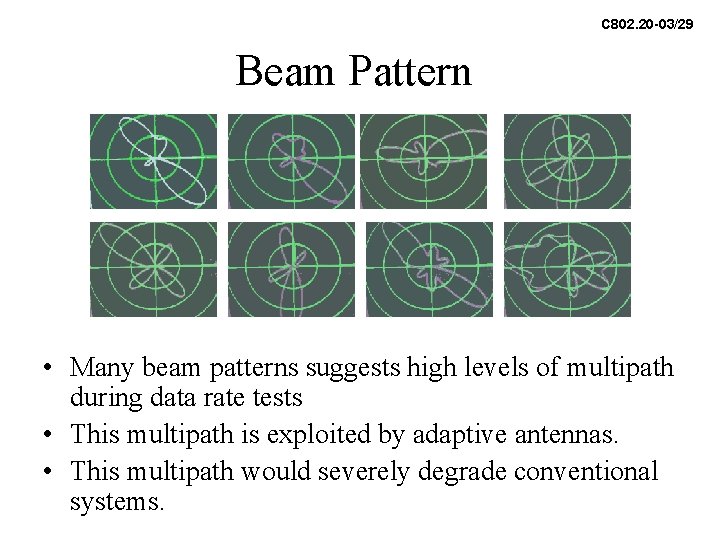
C 802. 20 -03/29 Beam Pattern • Many beam patterns suggests high levels of multipath during data rate tests • This multipath is exploited by adaptive antennas. • This multipath would severely degrade conventional systems.
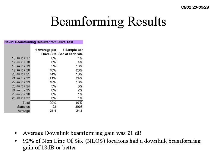
C 802. 20 -03/29 Beamforming Results • Average Downlink beamforming gain was 21 d. B • 92% of Non Line Of Site (NLOS) locations had a downlink beamforming gain of 18 d. B or better
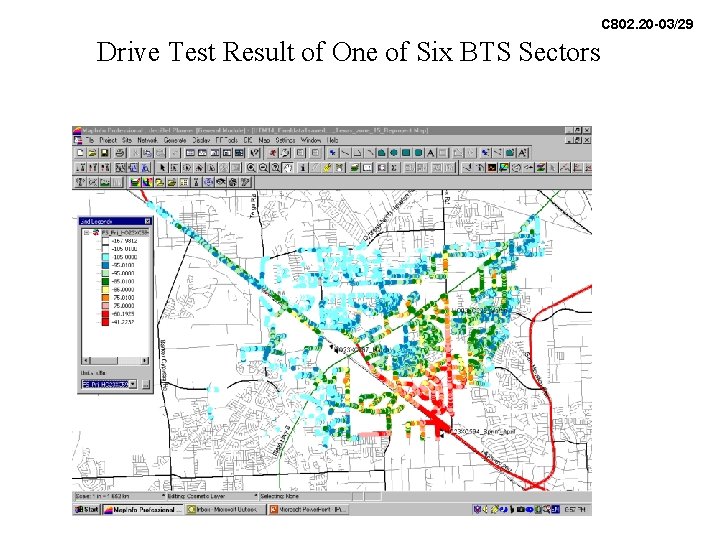
C 802. 20 -03/29 Drive Test Result of One of Six BTS Sectors
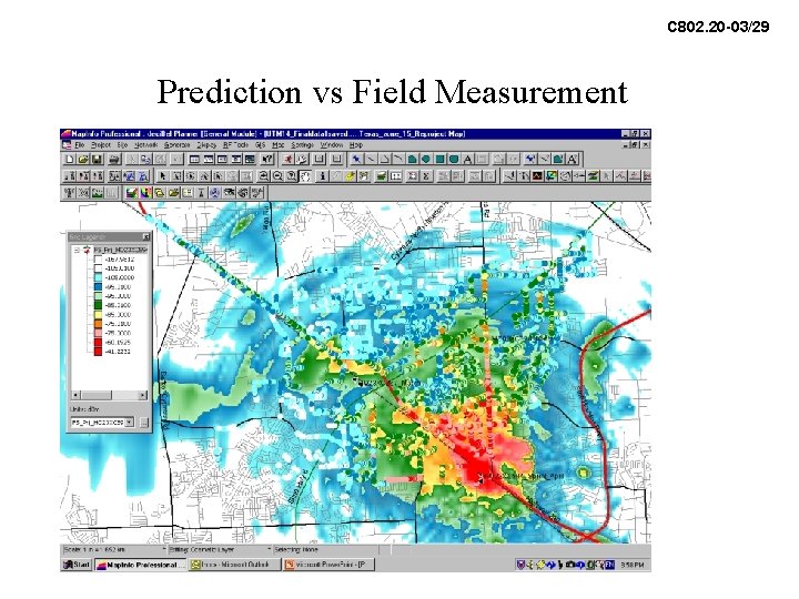
C 802. 20 -03/29 Prediction vs Field Measurement
C 802. 20 -03/29 FTP Raw Downlink Data Rates