Chapter 12 Local Area Networks Project 802 Ethernet


 • The data unit in the LLC level is called")


 It defines two categories: 1 - Baseband (Digital Signaling –")


 • Called Thin-Net, Cheap-Net, & 10 BASE 2 •")

 Maximum length")


 approved in")
- Slides: 32
Chapter 12 Local Area Networks • • Project 802 Ethernet Token Ring FDDI
Project 802 • In 1985, IEEE developed project 802. • It subdivided the data link layer into two sublayers: Logical Link Control (LLC) and Media Access Control (MAC). • LLC sublayer is non-architecture specific (same for all LANs). • MAC sublayer is architecture specific. • It also contains a section for internetworking to assure compatibility of different LANs.
OSI Model and Project 802
Project 802
IEEE 802. 1 • It is devoted to internetworking issues in LANs and MANs. • It assures compatibility between networks without requiring modification in addressing, access, … • Discussed in Chapter 20.
LLC and MAC • IEEE 802 uses the structure of an HDLC frame and divides it into two sets of functions: The first represents the end-user portions (logical address, control, and data) and is handled by the LLC sublayer. The second resolved contention for the shared media and is handled by the MAC sublayer. • The MAC contains the synchronization, flag, flow, and error control specification, as well as the physical address of the next station.
Protocol Data Unit (PDU) • The data unit in the LLC level is called PDU. • It contains four fields: Destination Service Access Point (DSAP), a Source Service Access Point (SSAP), a control field, and an information field. • DSAP and SSAP are used by LLC to identify the protocol stacks on the receiving and sending machines. • The first bit of the DSAP indicates whether the frame is intended for an individual or a group. While in SSAP, it indicated whether the packet is command or response. • The PDU has no flag, no CRC, and no station address.
PDU Format
PDU Control Field
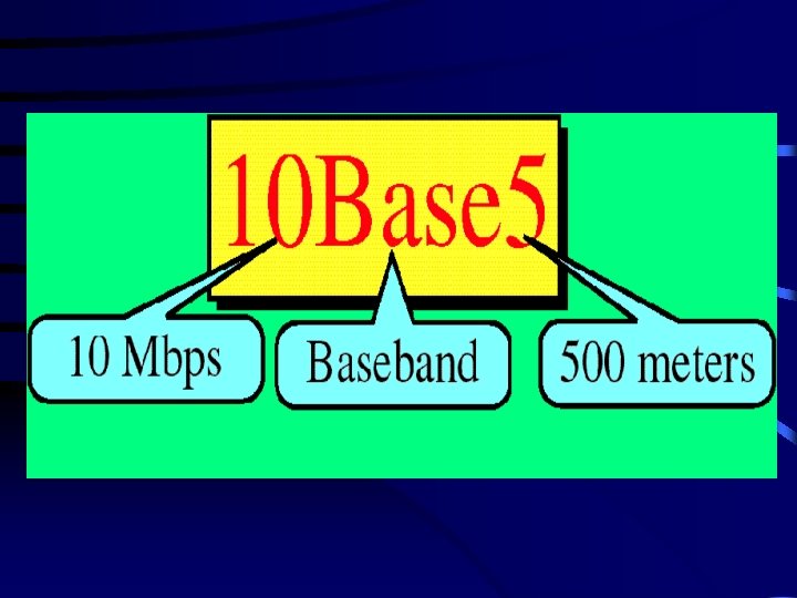
Ethernet (IEEE 802. 3) It defines two categories: 1 - Baseband (Digital Signaling – Manchester) 2 - Broadband (analog signaling – DPSK). Naming style: - Data Rate in Mbps Type of signaling - Maximum cable length or type of cable. Example : 10 Base 5.
802. 3 Baseband Digital 10 Base 5 10 Base 2 10 Base -T 1 Base 5 100 Base -T Broadband Analog 10 Braod 36
Access Method: CSMA/CD • The way in which network devices access the network medium • Carrier Sense Multiple Access with Collision Detection (CSMA/CD): media-access mechanism wherein devices ready to transmit data first check the channel for a carrier. If no carrier is sensed for a specific period of time, a device can transmit. • If two devices transmit at once, a collision occurs and is detected by all colliding devices. • Collision subsequently delays retransmissions from those devices for a random amount of time.
Evolution of CSMA/CD MA Multiple access CSMA Carrier sense Multiple access CSMA/CD Carrier sense Multiple access Collision detction
Rules for CSMA/Cd 1. If the medium is idle transmit, otherwise, go to 2. 2. If the medium is busy, continue to listen until the channel is idle, then transmit immediately. 3. If a collision is detected during transmission (high voltage), transmit a brief jamming signal to assure that all stations know that there has been a collision and then cease transmission. 4. After transmitting the jamming signal, wait a random amount of time, then go to 1.
• Addressing: Each station on an Ethernet network has its own Network Interface Card (NIC). The NIC contains the physical address of the station (MAC address) (6 -byte). • IEEE 802. 3 specifies one type of frame containing 7 fields. Ethernet does not provide any mechanism for acknowledging received fames (upper layer). - Preamble: 7 bytes of alternating 1 s and 0 s. - Start Frame Delimiter (SFD) 10101011: signals the beginning of the frame. - Destination Address, Source address 6 -bytes each - Length/type of PDU: number of bytes in PDU or type if the length is fixed. - PDU can be anywhere from 46 to 1500 bytes. - CRC-32.
MAC Frame
10 BASE 5 – Thick Ethernet Segments 200 -stations /segment, RG-8 cable
10 BASE 5
• Transceiver: Each station is attached by an AUI cable to an intermediary device called Medium Attachment Unit (MAU) or transceiver. It performs the CSMA/CD function and functions as a connecter. • AUI Cables: Each station is connected to the corresponding transceiver by an Attachment Unit Interface (AUI). It is a 15 -wire cable with plugs. Each end terminates in a DB-15 connector. • Transceiver Tap: a connecting mechanism to allow the transceiver to tap into the line at any point. It is sometimes called vampire.
Transceiver
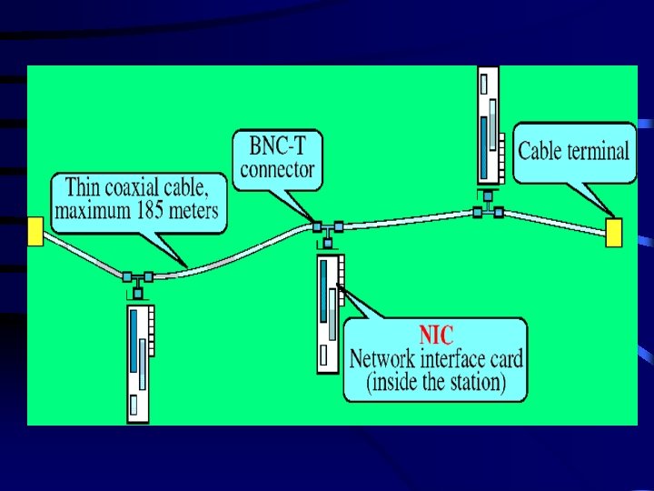
Thin Ethernet (10 BASE 2) • Called Thin-Net, Cheap-Net, & 10 BASE 2 • Pros: Reduced cost and ease of installation • Cons: Shorter range (185 m) and smaller capacity (30 nodes /segment) • Thin coaxial cable 75 RG-58. • BNC-T connector. • The NIC provides the functions of the transceiver.
10 BASE 2
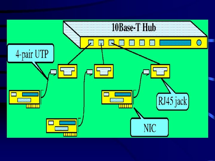
Twisted-Pair Ethernet 10 Base. T • • • Star Topology (Logical bus) Maximum length 100 m (Hub-to-Station). 4 -pair UTP cable. RJ-45 connector. Each station is connected to the Hub through a port. • The Hub fans out any transmitted frame to all of its connected stations.
10 BASET
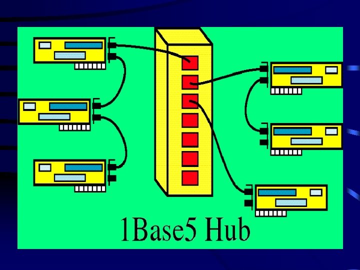
Star. LAN: 1 Base 5 • Very slow – infrequently used today • Its range can be increased using daisy chaining. • 10 stations can be linked each to the next in a chain.
1 BASE 5
Fast Ethernet 100 Base -T 4 100 Base-x 4 pare of UTP 100 Base -TX 2 pairs of UTP or STP 100 Base-Fx 2 optical fibers
Fast Ethernet • An extension to IEEE 802. 3 (802. 3 u) approved in 1995. • IEEE 802. 3 uses Manchester encoding running at 20 MHz. (two pulses /digit 10 Mbps). • 100 BASE-T 4 uses 4 -pair UTP: one is to the hub, one from the hub, and the other two are switchable to the current transmission direction. • Manchester in not used, 25 MHz ternary signals are used with 4 -bit/signal 100 Mbps