An implementation of IEEE 802 11 a WLAN
- Slides: 15
An implementation of IEEE 802. 11 a WLAN system using Subword Parallelism and its Quantization Error Evaluation Zaipeng Xie Muwu Hou Daphne J Franklin
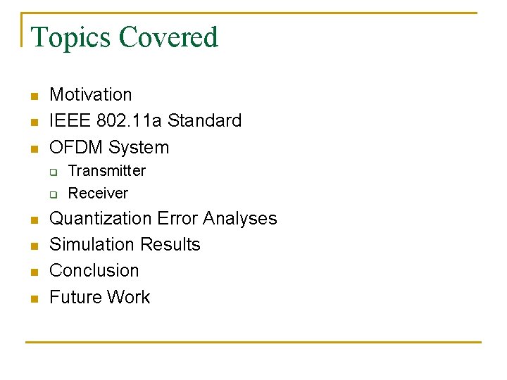
Topics Covered n n n Motivation IEEE 802. 11 a Standard OFDM System q q n n Transmitter Receiver Quantization Error Analyses Simulation Results Conclusion Future Work
Motivation n Increasing demand of greater communication capacity q n Effects of multipath fading and delay alleviated q q n High bandwidth efficiency Frequency selective fading Narrowband interference Exploit sub-word parallelism to optimize IFFT/FFT implementations
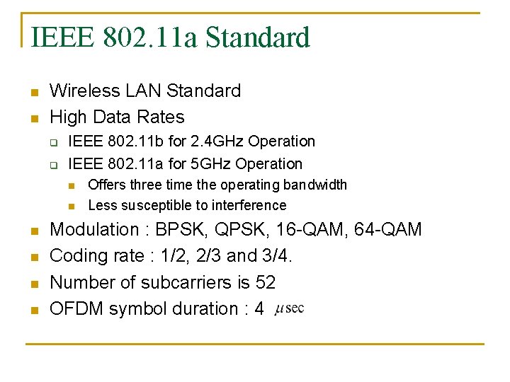
IEEE 802. 11 a Standard n n Wireless LAN Standard High Data Rates q q IEEE 802. 11 b for 2. 4 GHz Operation IEEE 802. 11 a for 5 GHz Operation n n n Offers three time the operating bandwidth Less susceptible to interference Modulation : BPSK, QPSK, 16 -QAM, 64 -QAM Coding rate : 1/2, 2/3 and 3/4. Number of subcarriers is 52 OFDM symbol duration : 4
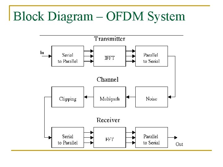
Block Diagram – OFDM System
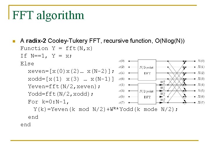
FFT algorithm n A radix-2 Cooley-Tukery FFT, recursive function, O(Nlog(N)) Function Y = fft(N, x) If N==1, Y = x; Else xeven=[x(0)x(2)… x(N-2)]; xodd=[x(1) x(3) … x(N-1)]; Yeven=fft(N/2, xeven); Yodd=fft(N/2, xodd); For k=0: N-1, Y(k)=Yeven(k mod N/2)+Wk*Yodd(k mode N/2); end
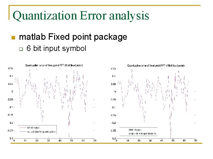
Quantization Error analysis n matlab Fixed point package q 6 bit input symbol
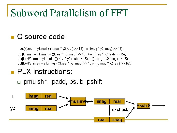
Subword Parallelism of FFT n C source code: out[k]. real = y 1. real + ((t. real * y 2. real) >> 15) - ((t. imag * y 2. imag) >> 15) out[k]. imag = y 1. imag + ((t. real * y 2. imag) >> 15) + ((t. imag * y 2. real) >> 15); out[k+N/2]. real = y 1. real - ((t. real * y 2. real) >> 15) + ((t. imag * y 2. imag) >> 15); out[k+N/2]. imag = y 1. imag - ((t. real * y 2. imag) >> 15) - ((t. imag * y 2. real) >> 15); n PLX instructions: q pmulshr , padd, psub, pshift t imag y 2 imag real Pmushr. 15 imag real excheck real imag Psub. 8
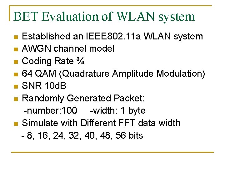
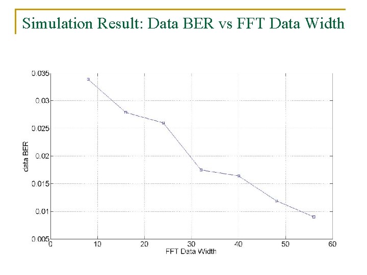
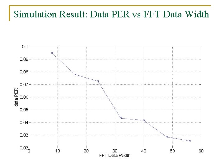
BET Evaluation of WLAN system n n n n Established an IEEE 802. 11 a WLAN system AWGN channel model Coding Rate ¾ 64 QAM (Quadrature Amplitude Modulation) SNR 10 d. B Randomly Generated Packet: -number: 100 -width: 1 byte Simulate with Different FFT data width - 8, 16, 24, 32, 40, 48, 56 bits
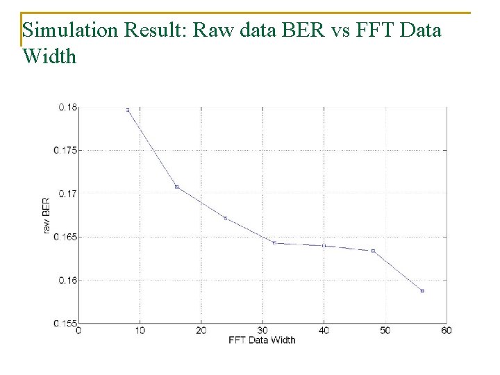
Simulation Result: Raw data BER vs FFT Data Width
Simulation Result: Data BER vs FFT Data Width
Simulation Result: Data PER vs FFT Data Width
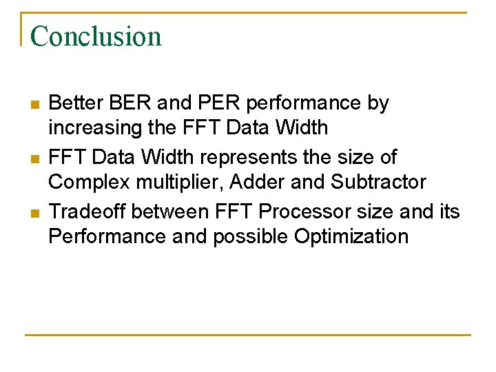
Conclusion n Better BER and PER performance by increasing the FFT Data Width represents the size of Complex multiplier, Adder and Subtractor Tradeoff between FFT Processor size and its Performance and possible Optimization
Future Work n Finish PLX subword parallelism implementation n Evaluate Error Rates vs FFT width in other Modulation mode: BPSK, QPSK, 16 -QAM, 64 QAM n Evaluate Error Rates vs FFT width with different Coding rate : 1/2, 2/3 and 3/4.
Thanks Questions?